Seeed Studio XIAO ESP32S3 与 MicroPython
MicroPython 是一个具有部分原生代码编译功能的 Python 解释器。它提供了 Python 3.5 功能的子集,专为嵌入式处理器和受限系统实现。它与 CPython 不同,您可以在这里了解更多关于差异的信息。
安装 MicroPython
安装 Esptool
如果您还没有安装 esptool.py,可以在您的电脑上使用 pip 进行安装:
pip install esptool
下载 XIAO ESP32S3 MicroPython 固件
您需要从 micropython.org 下载固件二进制文件 下载正确的 bin 文件后,导航到该文件夹,并在那里打开一个 cmd 终端。 截至最终草稿,最新版本的 bin 文件是:
ESP32_GENERIC_S3-20230602-v1.23.0.bin
将 XIAO ESP32S3 连接到您的电脑
您需要在将 type C USB 线缆插入电脑的同时,按住 XIAO ESP32S3 开发板上的 BOOT 按钮不放,以进入"bootloader"模式。
检查端口
找出您电脑上的所有串行设备。
- Linux
在 Linux 上,您可以使用 dmesg 命令查看已连接的设备:
dmesg | grep tty
或者,您可以使用 ls 列出串行设备:
ls /dev/ttyS* /dev/ttyUSB*
- Windows
在 Windows 上,您可以通过打开设备管理器来定位 USB 转串口端口地址。
- macOS
在 macOS 上,您可以使用 ls 命令列出可用的串口端口:
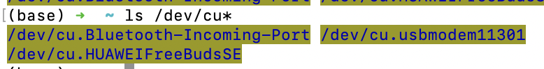
ls /dev/cu*
这将显示所有串口设备。
如果端口繁忙,您可以使用以下命令查找并终止使用该端口的进程(在 macOS 上): 识别使用端口的进程:
lsof | grep port
此命令列出打开的文件并搜索使用指定端口的任何进程。 从输出中找到进程ID(PID)并终止该进程:
kill -9 <PID>
将 PID 替换为找到的实际进程 ID。
擦除闪存
esptool.py --chip esp32s3 --port /dev/cu.usbmodem11301 erase_flash
将 '/dev/cu.usbmodem11301' 替换为您系统中正确的端口名称(例如 Windows 上的 COM3,Linux 上的 /dev/ttyUSB0)。
写入闪存
将固件刷写到 XIAO ESP32S3:
esptool.py --chip esp32s3 --port /dev/cu.usbmodem11301 --baud 460800 write_flash -z 0x0 ESP32_GENERIC_S3-20240602-v1.23.0.bin
再次提醒,将 '/dev/cu.usbmodem11301' 替换为正确的端口名称,将 'ESP32_GENERIC_S3-20240602-v1.23.0.bin' 替换为您的空白固件文件路径。 不要忘记通过 RTS 引脚进行硬复位。 然后就可以开始使用您喜欢的工具将脚本编译到 ESP32!
MicroPython 推荐编辑器
下面列出了一些流行的工具。
1. Thonny
安装并打开 thonny,然后按照说明配置 Thonny:
pip install thonny
#open thonny after installation
thonny
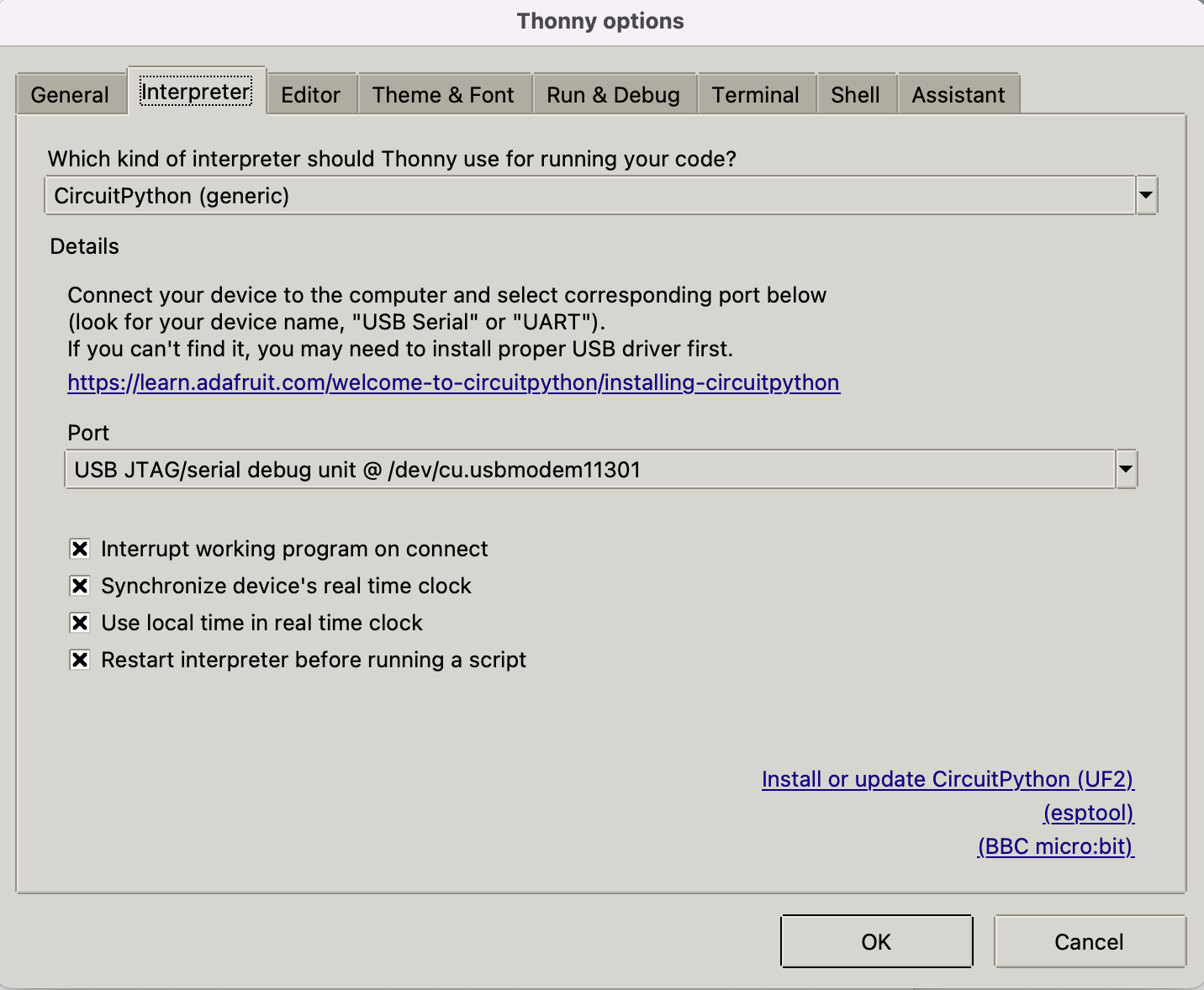
转到 Run-->Configure Interpreter,确保 Thonny 选项中的 Interpreter 选项卡如下所示,选择"CircuitPython (generic)"和端口:
在对话框中点击"OK",您应该会在 thonny 窗口底部看到 Micropython shell,如下图所示。 逐行将脚本输入到 Shell 中以获取闪存和内存大小:
import esp
esp.flash_size()
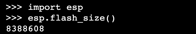
恭喜您成功在 XIAO ESP32S3 上使用 Thonny 设置了 MicroPython!
2. Arduino Lab for MicroPython
下载 Arduino lab for MicroPython 并将设备连接到您的电脑。
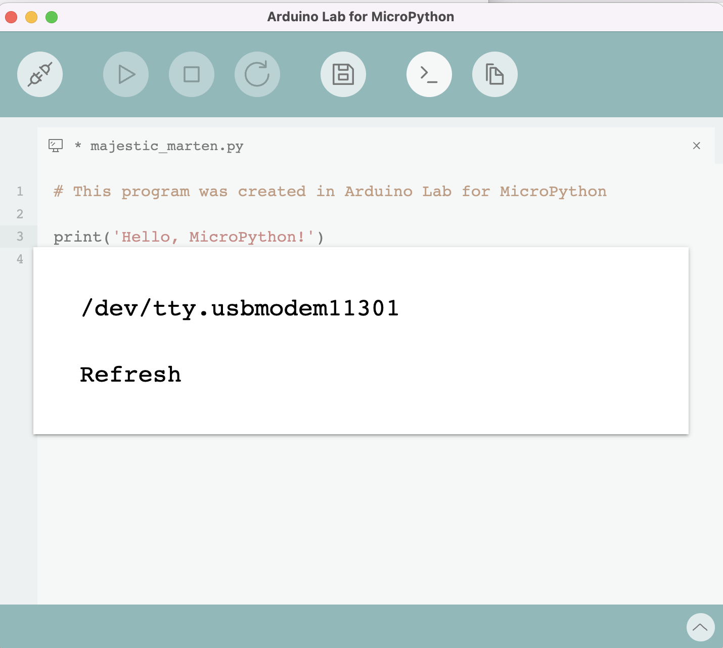
代码如下:
from machine import Pin
import time

# Define the LED pin
led = Pin(6, Pin.OUT)  # Use correct gpio

# Blink the LED in a loop
while True:
    led.value(1)   # Turn the LED on
    time.sleep(1)  # Wait for a second
    led.value(0)   # Turn the LED off
    time.sleep(1)  # Wait for a second
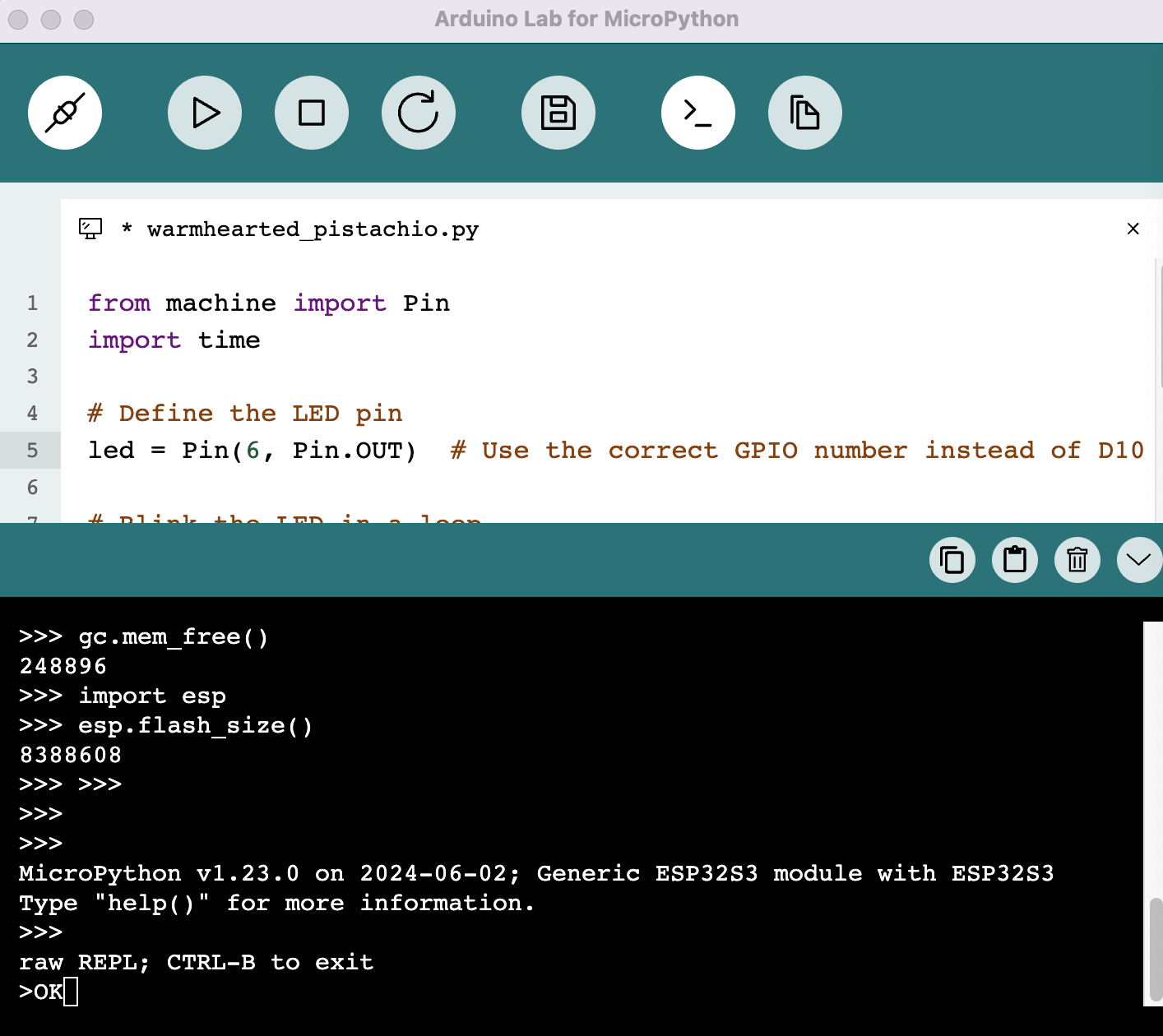
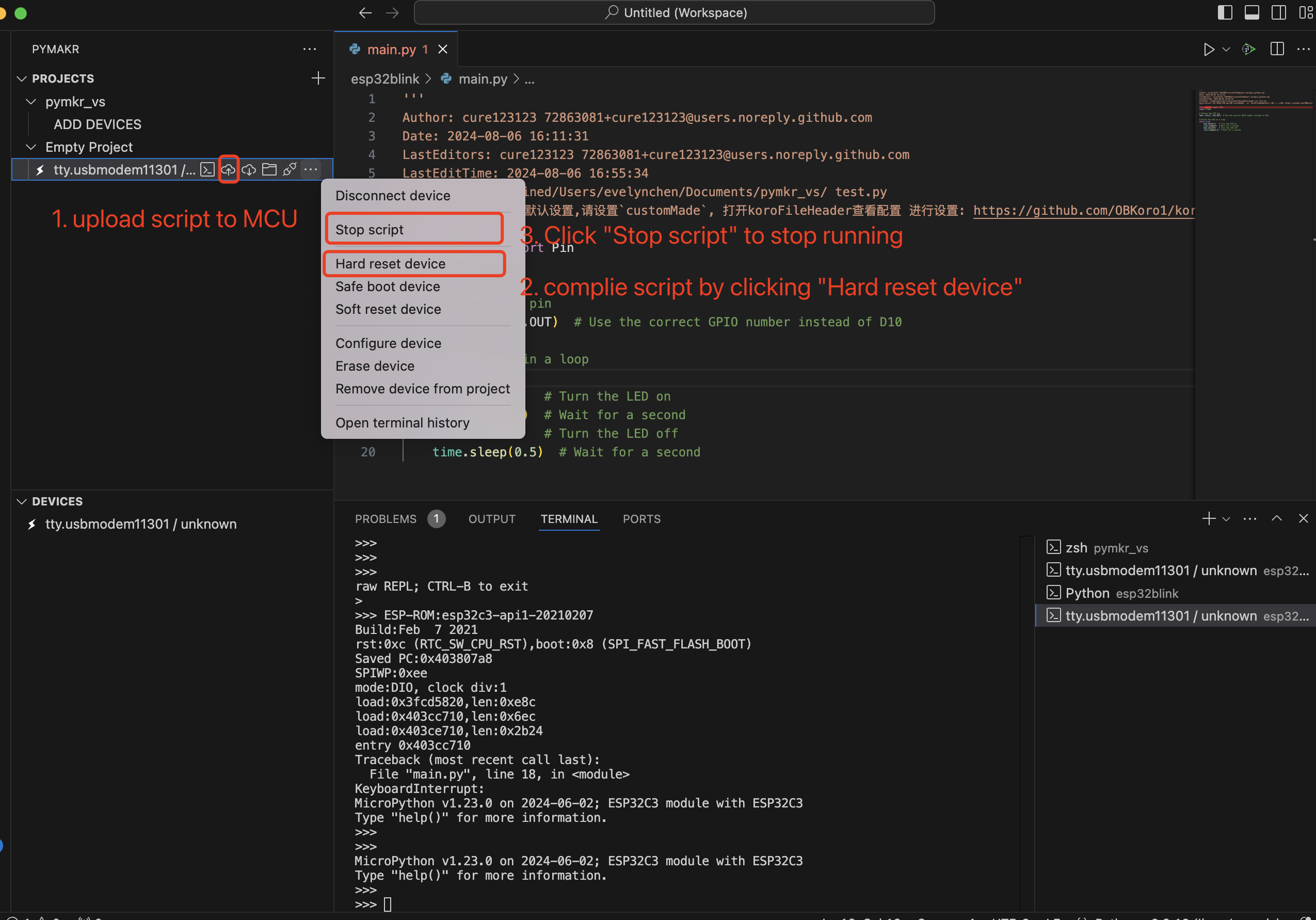
3. Visual Studio Code 上的 Pymakr
- 安装 Pymakr 按照安装说明来安装 Pymakr。
- 将您的 XIAO ESP32S3 连接到计算机。
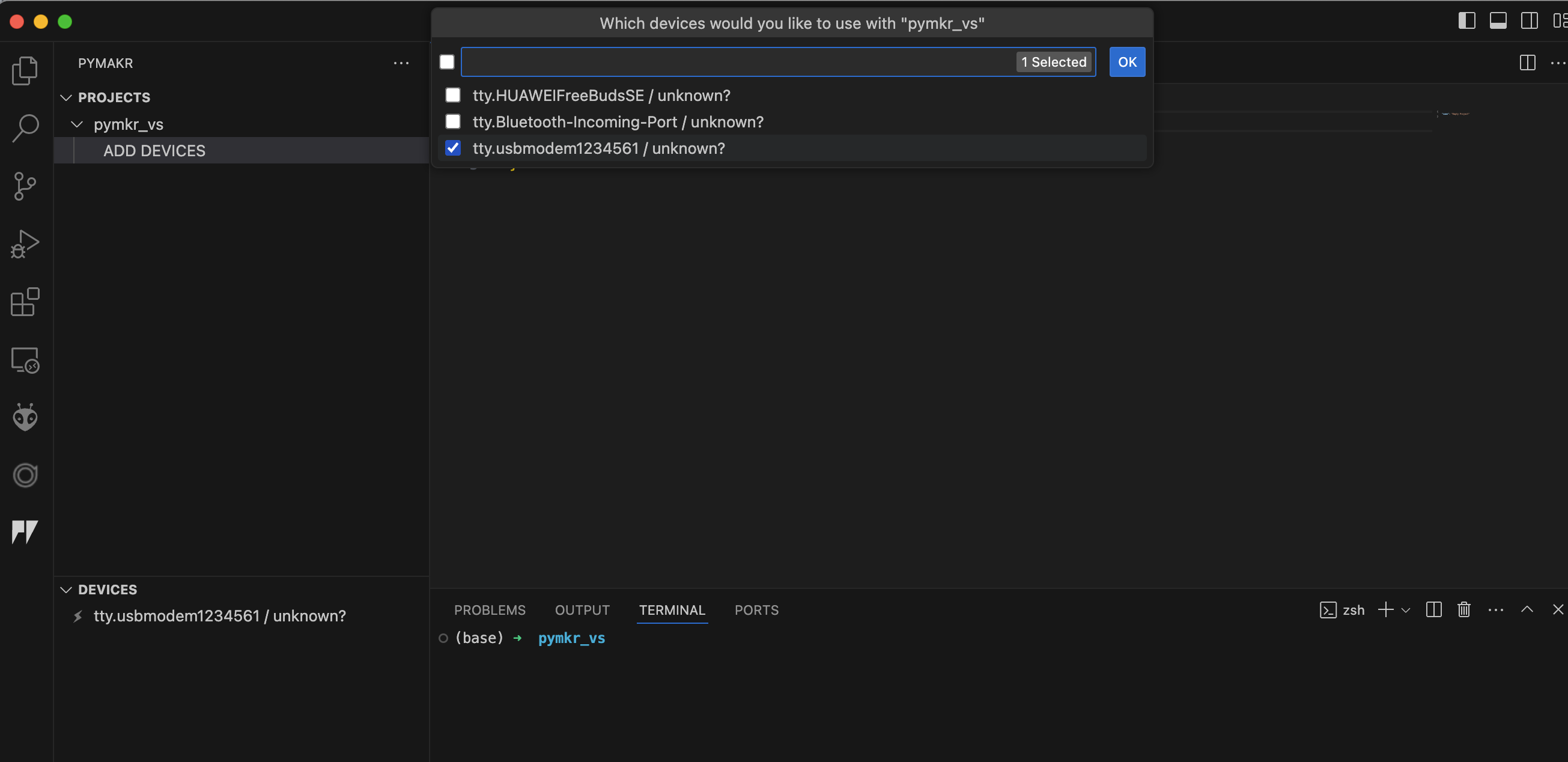
- 创建新项目 打开 VS Code 并为您的微控制器创建一个新项目。
- 添加新的 Python 文件 在您的项目中创建一个新的 Python 文件。
- 将脚本上传到 MCU 并编译脚本
4. uPtCraft IDE
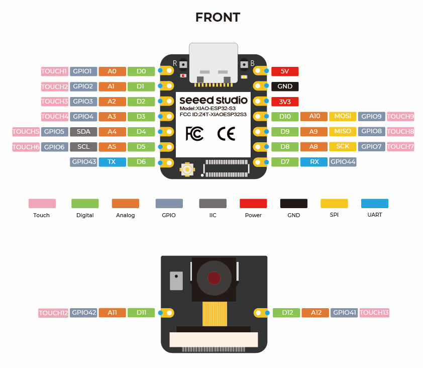
引脚定义/端口信息
XIAO ESP32S3 上的 MicroPython 入门
这里是micropython 操作 ESP32 的快速参考。 有关micropython 库的更多知识。
通用板控制
MicroPython REPL(Read-Eval-Print-Loop) 在 UART0 (GPIO1=TX, GPIO3=RX) 上,波特率为 115200。Tab 补全功能对于查找对象的方法很有用。粘贴模式 (ctrl-E) 对于将大段 Python 代码粘贴到 REPL 中很有用。 可以在 MicroPython 中使用 dir() 函数(类似于 Python)来列出对象的属性和方法。 例如,在 shell 中输入 dir(machine):
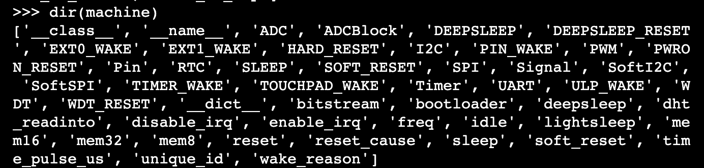
machine 模块:
import machine
machine.freq()          # get the current frequency of the CPU, for esp32s3 is 240000000
machine.freq(160000000) # set the CPU frequency to 160 MHz
#frequency must be 20MHz, 40MHz, 80Mhz, 160MHz or 240MHz
The esp module:
import esp

esp.osdebug(None)       # turn off vendor O/S debugging messages
esp.osdebug(0)          # redirect vendor O/S debugging messages to UART(0)

# low level methods to interact with flash storage
esp.flash_size()
esp.flash_user_start()
esp.flash_erase(sector_no)
esp.flash_write(byte_offset, buffer)
esp.flash_read(byte_offset, buffer)
esp32 模块: ESP32C3、ESP32S2 和 ESP32S3 具有内置温度传感器,可返回摄氏度温度值:
import esp32
esp32.mcu_temperature() # read the internal temperature of the MCU, in Celsius
Network-WLAN
Network 模块: 更多信息请参考这里。
import network

wlan = network.WLAN(network.STA_IF) # create station interface
wlan.active(True)       # activate the interface
wlan.scan()             # scan for access points
wlan.isconnected()      # check if the station is connected to an AP
wlan.connect('ssid', 'key') # connect to an AP
wlan.config('mac')      # get the interface's MAC address
wlan.ifconfig()  # get the interface's IPv4 addresses

ap = network.WLAN(network.AP_IF) # create access-point interface
ap.config(ssid='ESP-AP') # set the SSID of the access point
ap.config(max_clients=10) # set how many clients can connect to the network
ap.active(True)         # activate the interface
一个用于连接到本地 WiFi 网络的有用函数是:
def do_connect():
    import network
    wlan = network.WLAN(network.STA_IF)
    wlan.active(True)
    if not wlan.isconnected():
        print('connecting to network...')
        wlan.connect('ssid', 'key') #replace the ssid and key
        while not wlan.isconnected():
            pass
    print('network config:', wlan.ifconfig())
Delay and timing
The time module:
import time

time.sleep(1)           # sleep for 1 second
time.sleep_ms(500)      # sleep for 500 milliseconds
time.sleep_us(10)       # sleep for 10 microseconds
start = time.ticks_ms() # get millisecond counter
delta = time.ticks_diff(time.ticks_ms(), start) # compute time difference
定时器
ESP32 端口有四个硬件定时器。使用 class 配合定时器 ID 从 0 到 3(包含):
from machine import Timer

tim0 = Timer(0)
tim0.init(period=5000, mode=Timer.ONE_SHOT, callback=lambda t:print(0))

tim1 = Timer(1)
tim1.init(period=2000, mode=Timer.PERIODIC, callback=lambda t:print(1))
周期以毫秒为单位。 此端口目前不支持虚拟定时器。
引脚和 GPIO
machine.Pin 类:
from machine import Pin

p2 = Pin(2, Pin.OUT)    # create output pin on GPIO2
p2.on()                 # set pin to "on" (high) level
p2.off()                # set pin to "off" (low) level
p2.value(1)             # set pin to on/high

p3 = Pin(3, Pin.IN)     # create input pin on GPIO3
print(p3.value())       # get value, 0 or 1

p4 = Pin(4, Pin.IN, Pin.PULL_UP) # enable internal pull-up resistor
p5 = Pin(5, Pin.OUT, value=1) # set pin high on creation
p6 = Pin(6, Pin.OUT, drive=Pin.DRIVE_3) # set maximum drive strength
可用引脚来自以下范围(包含):1,2,3,4,5,6,7,8,9,43,44。这些对应于ESP32S3芯片的实际GPIO引脚编号。
UART(串行总线)
machine.UART 类:
from machine import UART

uart1 = UART(1, baudrate=9600, tx=43, rx=44)
uart1.write('hello')  # write 5 bytes
uart1.read(5)         # read up to 5 bytes
ESP32C3 有一个硬件 UART。引脚列表如下:
| UART | Pin |
|---|---|
| TX | 43 |
| RX | 44 |
PWM(脉宽调制)
PWM 可以在所有支持输出的引脚上启用。基础频率范围可以从 1Hz 到 40MHz,但存在权衡;随着基础频率的增加,占空比分辨率会降低。 machine.PWM 类:
from machine import Pin, PWM

pwm2 = PWM(Pin(2), freq=5000, duty_u16=32768) # create PWM object from a pin
freq = pwm2.freq()         # get current frequency
pwm2.freq(1000)            # set PWM frequency from 1Hz to 40MHz

duty = pwm2.duty()         # get current duty cycle, range 0-1023 (default 512, 50%)
pwm2.duty(256)             # set duty cycle from 0 to 1023 as a ratio duty/1023, (now 25%)

duty_u16 = pwm2.duty_u16() # get current duty cycle, range 0-65535
pwm2.duty_u16(2**16*3//4)  # set duty cycle from 0 to 65535 as a ratio duty_u16/65535, (now 75%)

duty_ns = pwm2.duty_ns()   # get current pulse width in ns
pwm2.duty_ns(250_000)      # set pulse width in nanoseconds from 0 to 1_000_000_000/freq, (now 25%)

pwm2.deinit()              # turn off PWM on the pin

pwm3 = PWM(Pin(3), freq=20000, duty=512)  # create and configure in one go
print(pwm3)                               # view PWM settings
ADC(模数转换)
在 XIAO ESP32S3 上,ADC 功能可在引脚 1、2、3、4、5、6、7、8、9 上使用。 machine.ADC 类:
from machine import ADC

adc = ADC(pin)        # create an ADC object acting on a pin
val = adc.read_u16()  # read a raw analog value in the range 0-65535
val = adc.read_uv()   # read an analog value in microvolts
SPI
软件 SPI 总线
软件 SPI(使用位操作)可在所有引脚上工作,通过 machine.SoftSPI 类访问:
from machine import Pin, SoftSPI

# construct a SoftSPI bus on the given pins
# polarity is the idle state of SCK
# phase=0 means sample on the first edge of SCK, phase=1 means the second
spi = SoftSPI(baudrate=100000, polarity=1, phase=0, sck=Pin(2), mosi=Pin(4), miso=Pin(6))

spi.init(baudrate=200000) # set the baudrate

spi.read(10)            # read 10 bytes on MISO
spi.read(10, 0xff)      # read 10 bytes while outputting 0xff on MOSI

buf = bytearray(50)     # create a buffer
spi.readinto(buf)       # read into the given buffer (reads 50 bytes in this case)
spi.readinto(buf, 0xff) # read into the given buffer and output 0xff on MOSI

spi.write(b'12345')     # write 5 bytes on MOSI

buf = bytearray(4)      # create a buffer
spi.write_readinto(b'1234', buf) # write to MOSI and read from MISO into the buffer
spi.write_readinto(buf, buf) # write buf to MOSI and read MISO back into buf
硬件 SPI 总线
硬件 SPI 通过 machine.SPI 类访问,具有与上述软件 SPI 相同的方法:
from machine import Pin, SPI

hspi = SPI(1, 10000000)
hspi = SPI(1, 10000000, sck=Pin(7), mosi=Pin(9), miso=Pin(8))
| SPI | 引脚 |
|---|---|
| SCK | D7 |
| MOSI | D9 |
| MISO | D8 |
I2C
软件 I2C 总线
软件 I2C(使用位操作)可在所有具有输出功能的引脚上工作,通过 machine.SoftI2C 类访问:
from machine import Pin, SoftI2C

i2c = SoftI2C(scl=Pin(6), sda=Pin(5), freq=100000)

i2c.scan()              # scan for devices

i2c.readfrom(0x3a, 4)   # read 4 bytes from device with address 0x3a
i2c.writeto(0x3a, '12') # write '12' to device with address 0x3a

buf = bytearray(10)     # create a buffer with 10 bytes
i2c.writeto(0x3a, buf)  # write the given buffer to the peripheral
硬件 I2C 总线
驱动程序通过 machine.I2C 类访问,具有与上述软件 I2C 相同的方法:
from machine import Pin, I2C
i2c = I2C(0, scl=Pin(6), sda=Pin(5), freq=400000)
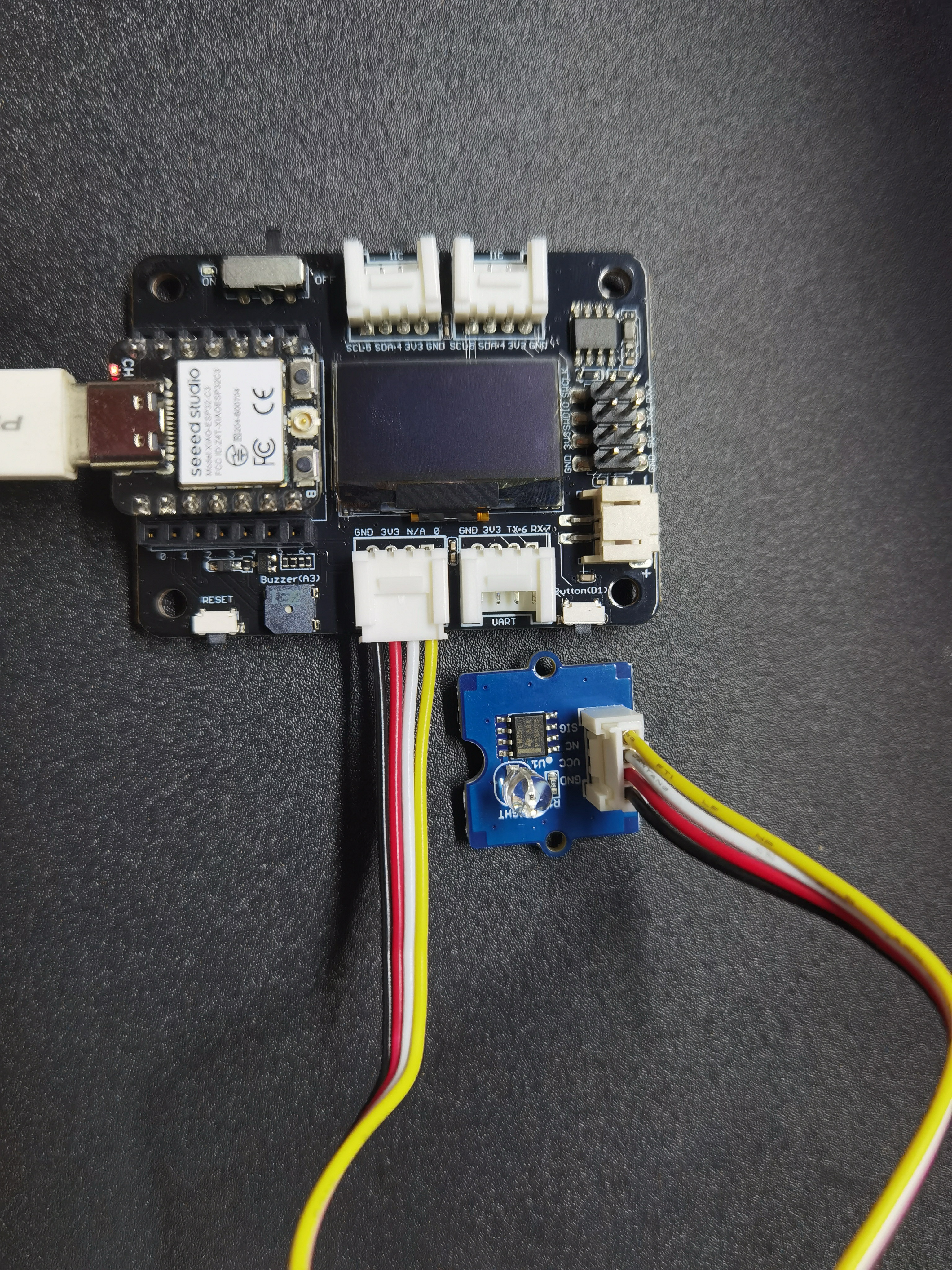
XIAO 扩展底板
前提条件:
| XIAO ESP32S3 已焊接排针 | XIAO 扩展底板 | Grove 光传感器 |
|---|---|---|
 |  |  |
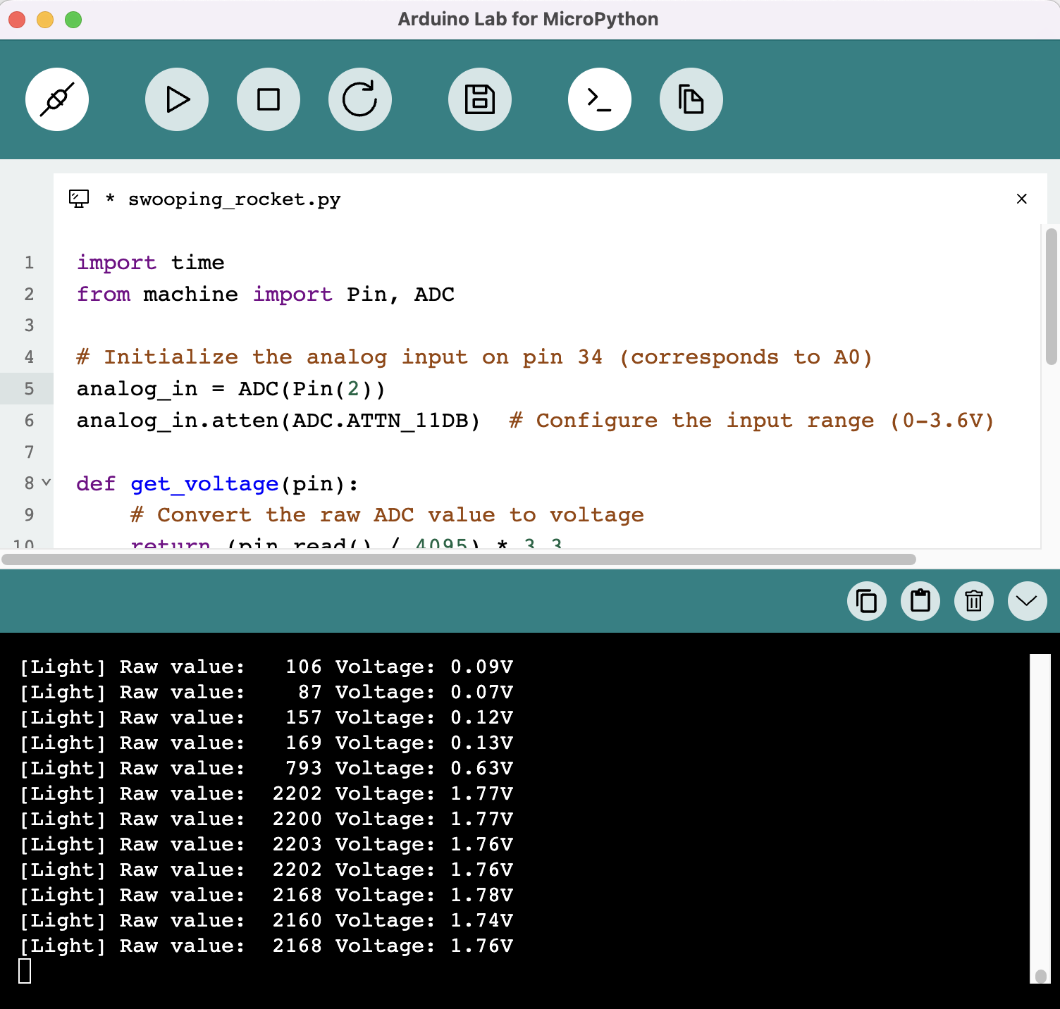
读取光传感器数据
import time
from machine import Pin, ADC

# Initialize the analog input on pin 2 (corresponds to A0)
analog_in = ADC(Pin(1))
analog_in.atten(ADC.ATTN_11DB)  # Configure the input range (0-3.6V)

def get_voltage(pin):
    # Convert the raw ADC value to voltage
    return (pin.read() / 4095) * 3.3

while True:
    # Read the raw analog value
    raw_value = analog_in.read()
    # Convert the raw value to voltage
    voltage = get_voltage(analog_in)

    # Print the raw value and voltage to the serial console
    print("[Light] Raw value: {:5d} Voltage: {:.2f}V".format(raw_value, voltage))

    # Delay for a short period of time before reading again
    time.sleep(1)
点亮OLED屏幕
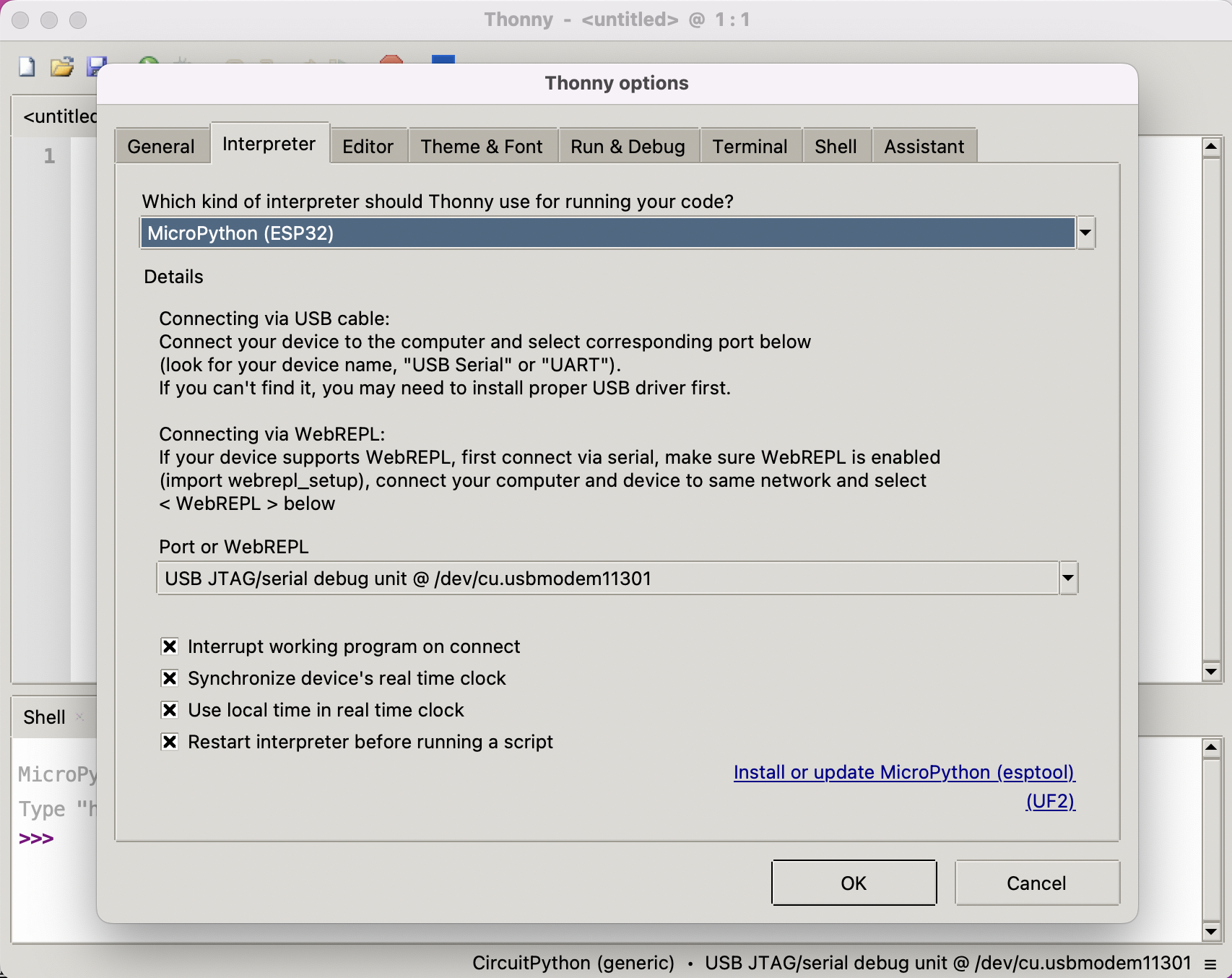
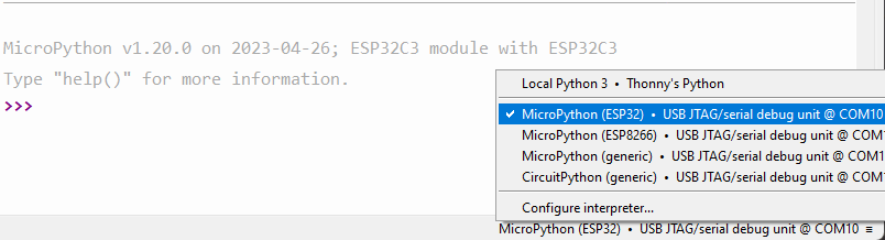
插入您的XIAO ESP32S3,打开Thonny并点击右下角配置解释器 选择解释器- Micropython (ESP32) 和 端口 >>> 点击确定
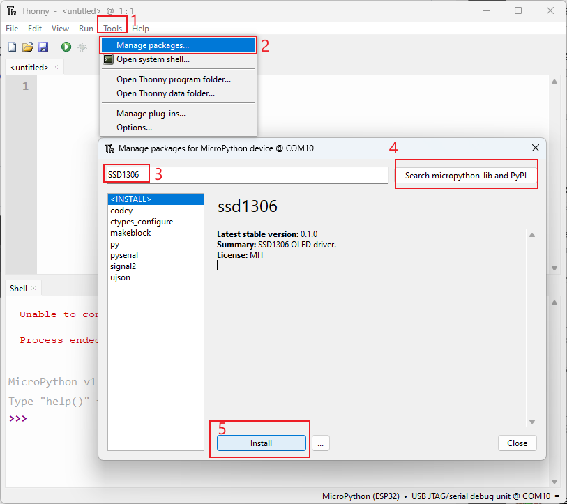
如果一切顺利,您将在shell中看到输出 从MicroPython安装ssd1306库。 点击"工具" >>> 点击"管理包" >>> 输入库的名称 >>> 点击"搜索micropython-lib和PyPl"
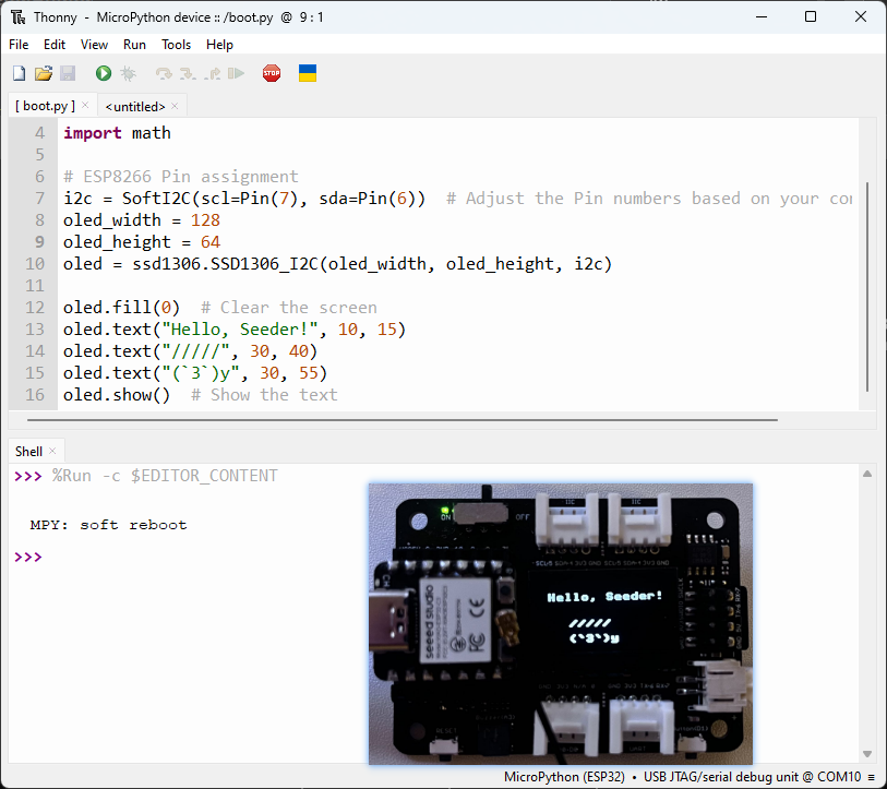
运行脚本并将其烧录到开发板。 完成编码后,点击绿色按钮运行脚本。
import time
from machine import Pin, SoftI2C
import ssd1306
import math

# ESP8266 Pin assignment
i2c = SoftI2C(scl=Pin(6), sda=Pin(5))  # Adjust the Pin numbers based on your connections
oled_width = 128
oled_height = 64
oled = ssd1306.SSD1306_I2C(oled_width, oled_height, i2c)

oled.fill(0)  # Clear the screen
oled.text("Hello, Seeder!", 10, 15)
oled.text("/////", 30, 40)
oled.text("(`3`)y", 30, 55)
oled.show()  # Show the text
摄像头流媒体测试
摄像头流媒体测试也适用于带摄像头的 ESP32S3 sense,请参考这里。
感谢您阅读本文!欢迎在评论中分享您的想法。
资源
- 适用于 XIAO ESP32S3 的 MicroPython 固件二进制文件
技术支持与产品讨论
感谢您选择我们的产品!我们在这里为您提供不同的支持,以确保您使用我们产品的体验尽可能顺畅。我们提供多种沟通渠道,以满足不同的偏好和需求。