使用 Seeed Studio XIAO MG24 进行引脚复用
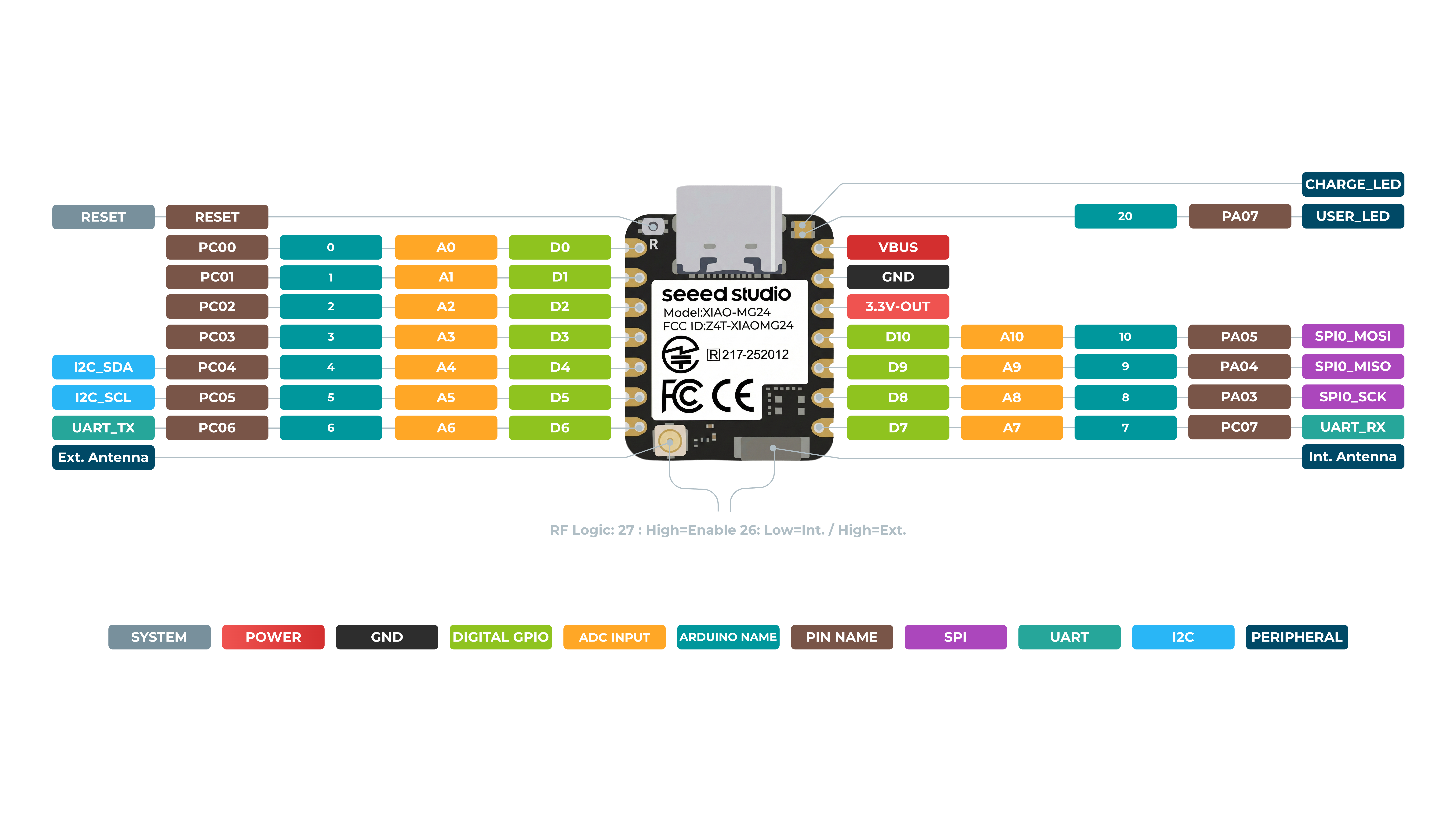
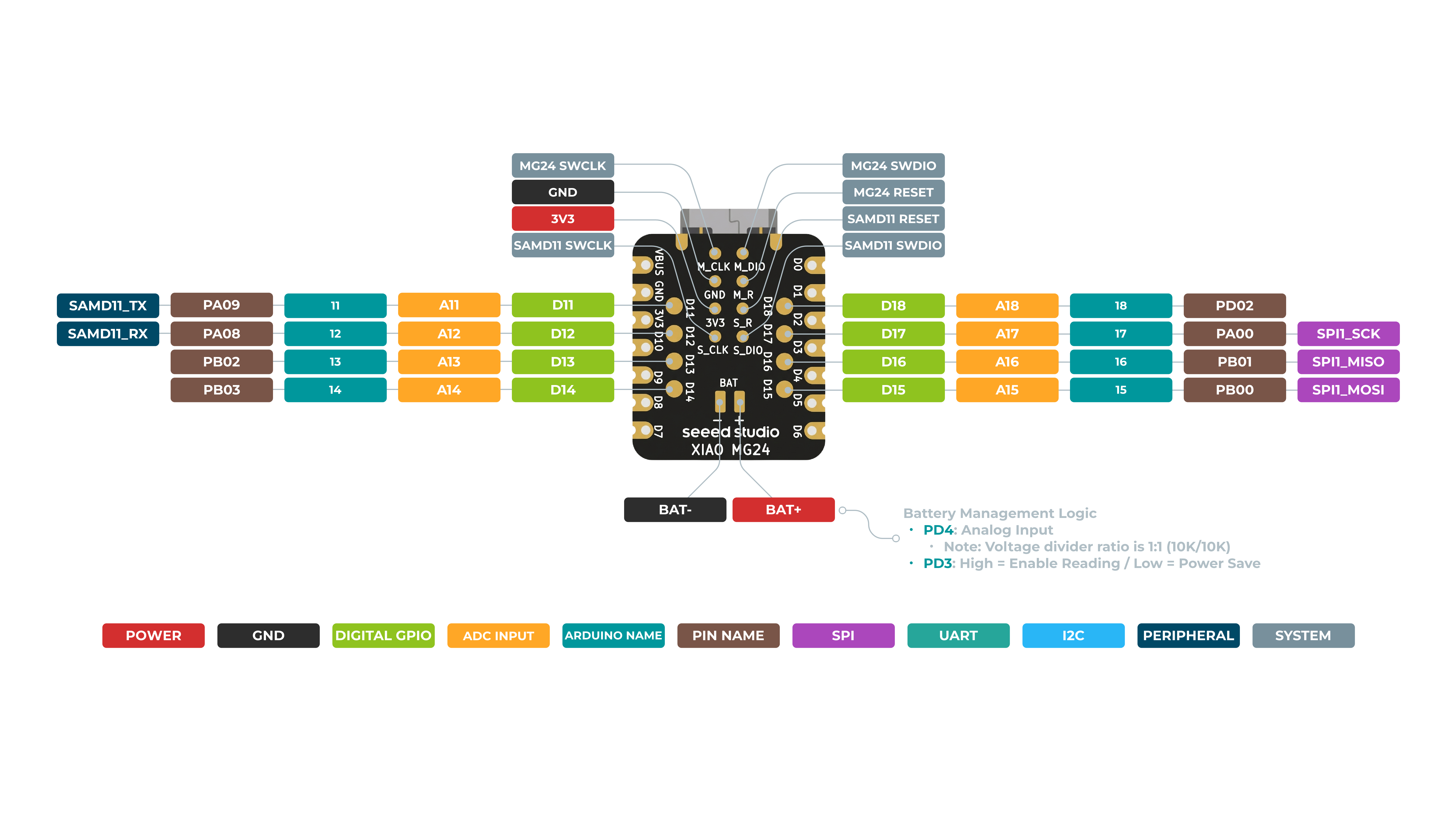
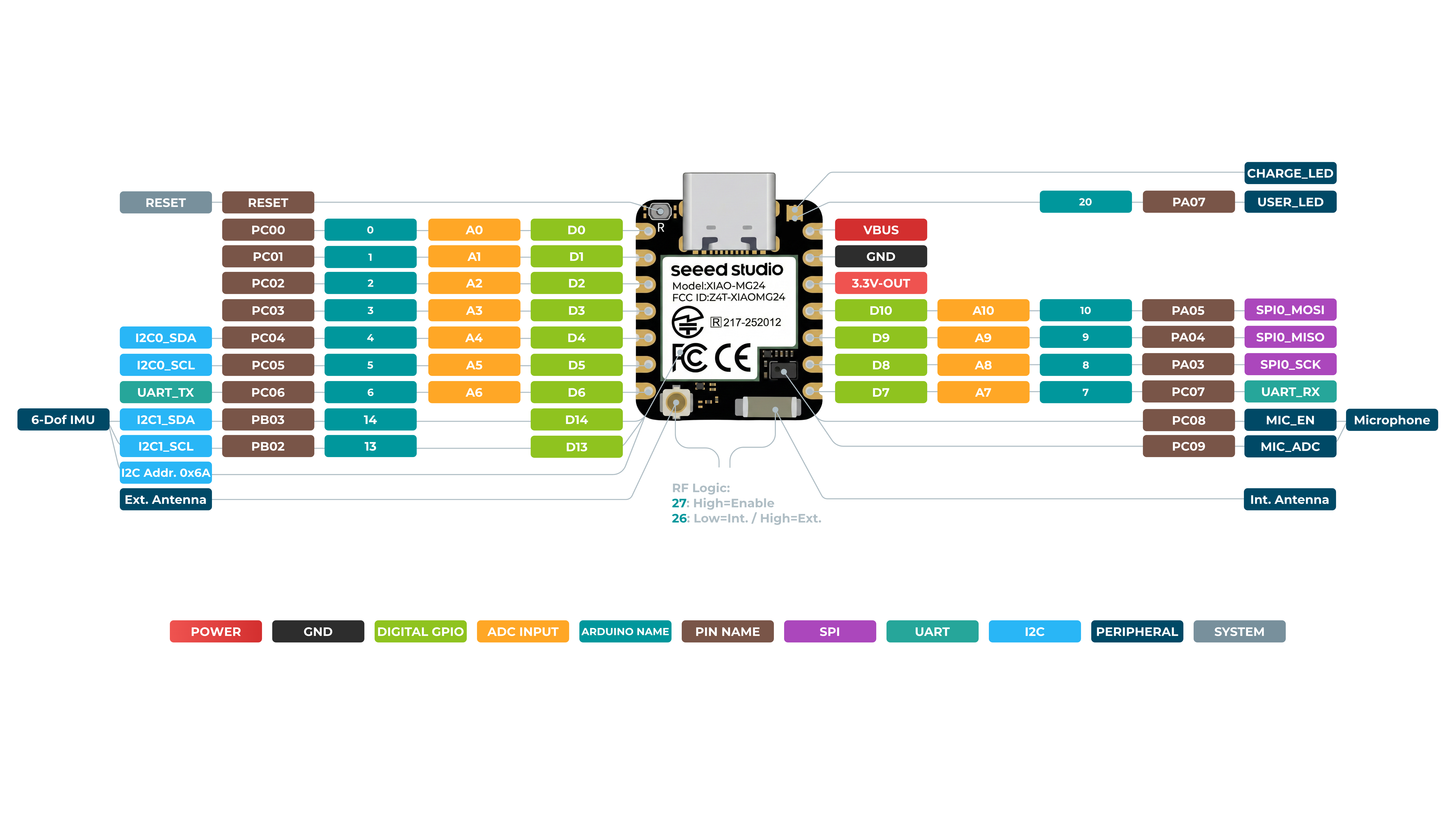
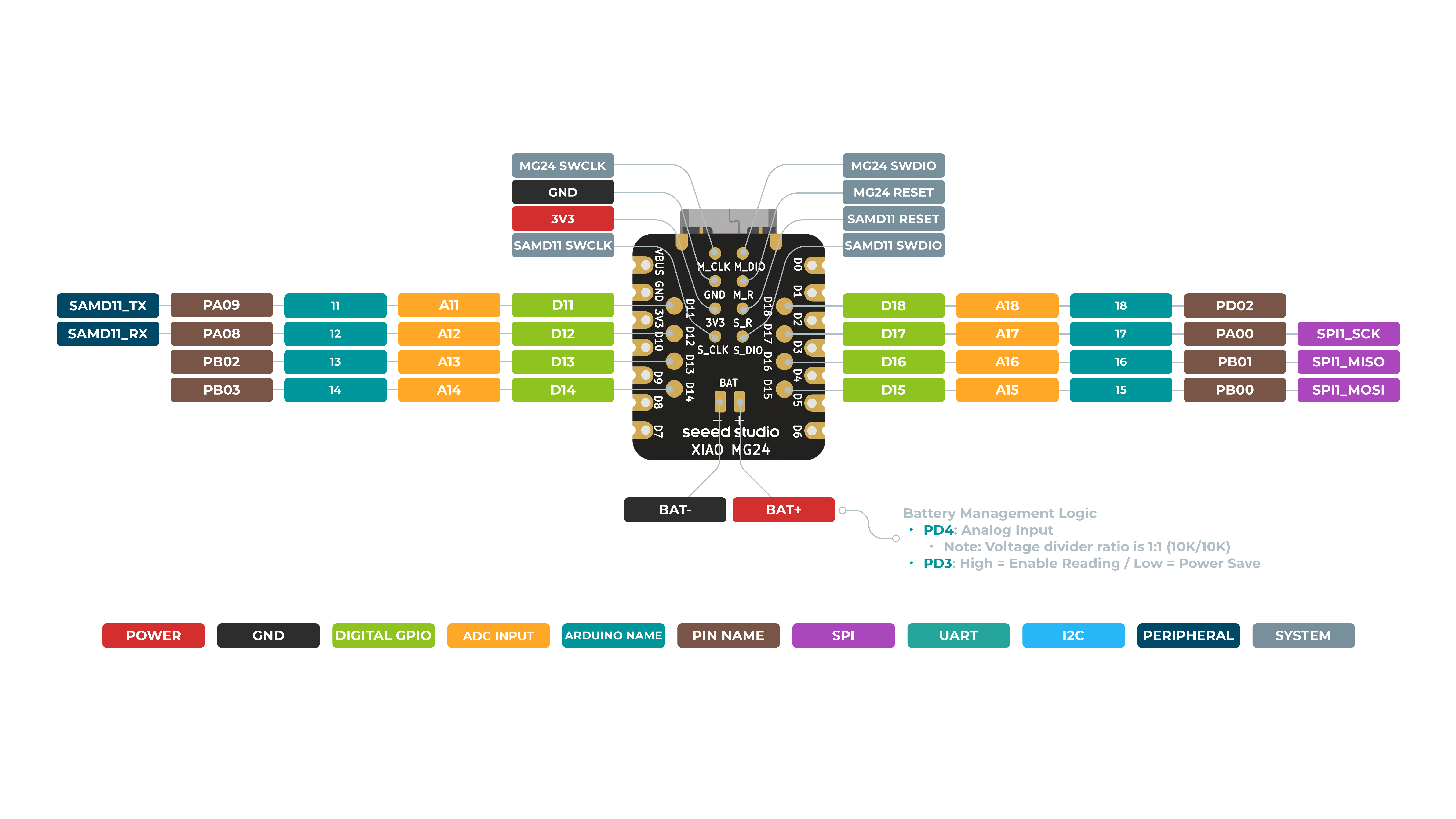
XIAO MG24 具有多达 22 个常规引脚、18 个模拟引脚、18 个数字引脚、2 组 SPI、2 组 UART、2 组 I2C,并支持 全部 PWM。它为我们提供了非常丰富的引脚资源。在本篇 wiki 中,我将教你如何驱动这些引脚,从而高效地利用它们 😀!
硬件概述
数字引脚
硬件准备
| Seeed Studio XIAO MG24 Sense | Seeed Studio Expansion Base for XIAO with Grove OLED | Grove - Relay |
|---|---|---|
 | 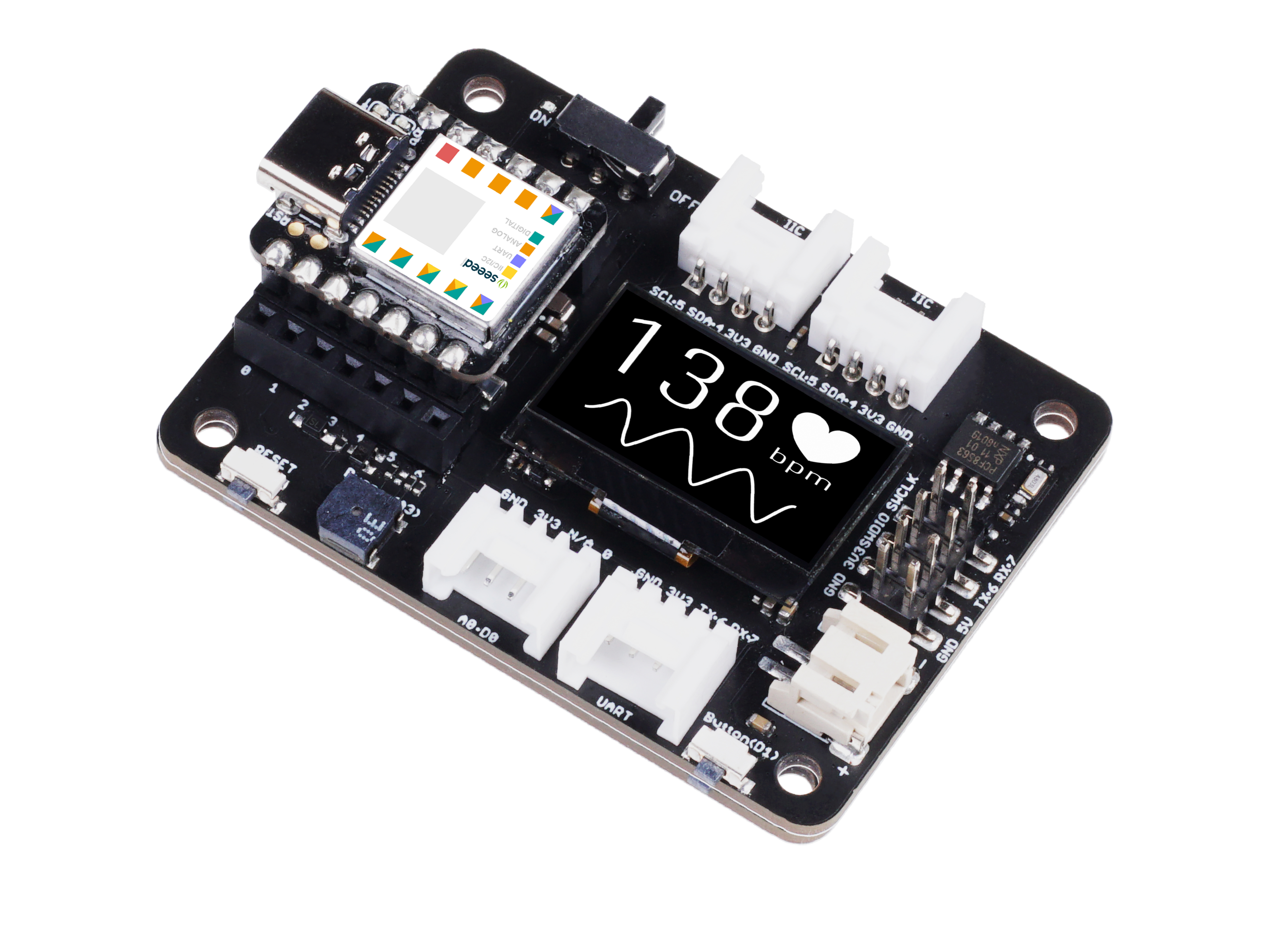 |  |
请将 XIAO MG24(Sense)安装到扩展板上,并通过 Grove 线缆将继电器连接到扩展板的 A0/D0 接口。最后,通过 USB-C 线缆将 XIAO 连接到电脑。
软件实现
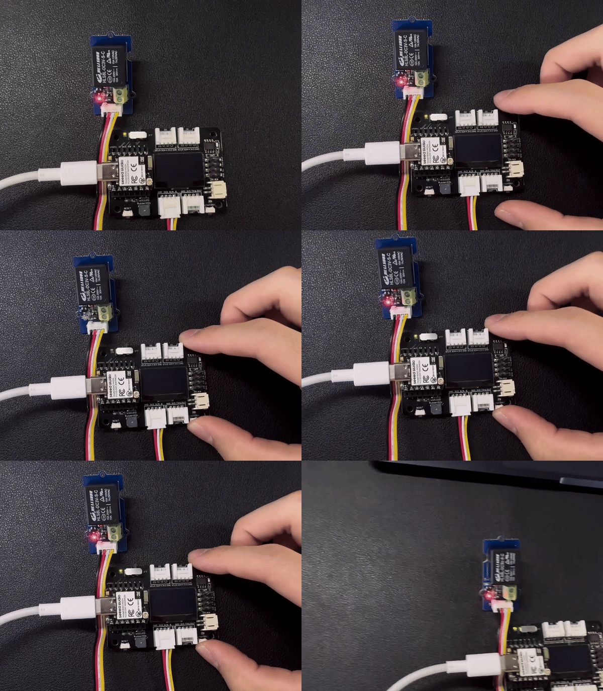
在本示例中,我们将通过连接在 XIAO 扩展板上的按键来控制继电器的开关状态。当按下按键时,继电器吸合;当松开按键时,继电器断开。
const int buttonPin = D1;     // the number of the pushbutton pin
int buttonState = 0;          // variable for reading the pushbutton status
const int relayPin = D0;

void setup() {
  // initialize the Relay pin as an output:
  pinMode(relayPin, OUTPUT);
  // initialize the pushbutton pin as an input:
  pinMode(buttonPin, INPUT_PULLUP);
}

void loop() {
  // read the state of the pushbutton value:
  buttonState = digitalRead(buttonPin);

  // check if the pushbutton is pressed. If it is, the buttonState is HIGH:
  if (buttonState == HIGH) {
    // turn Relay on:
    digitalWrite(relayPin, HIGH);
  } else {
    // turn Relay off:
    digitalWrite(relayPin, LOW);
  }
}
结果示意图
如果一切顺利,在上传程序后,你应该能看到如下效果。
数字引脚作为 PWM 使用
XIAO MG24(Sense)上的所有 GPIO 引脚都支持 PWM 输出。因此,你可以使用任意引脚输出 PWM,用于调节灯光亮度、控制舵机等功能。
硬件准备
| Seeed Studio XIAO MG24 Sense | Seeed Studio Expansion Base for XIAO with Grove OLED | Grove - Variable Color LED |
|---|---|---|
| |  |
请将 XIAO MG24(Sense)安装到扩展板上,然后使用 Grove 线缆将 Variable Color LED 连接到扩展板的 A0/D0 接口。最后,通过 USB-C 线缆将 XIAO 连接到电脑。
软件实现
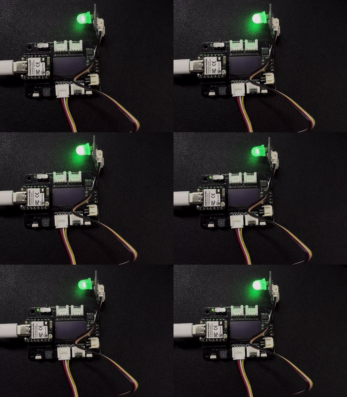
在本示例中,我们将演示如何使用 PWM 输出来控制灯光的亮度。
int LED_pin = D0;    // LED connected to digital pin 10

void setup() {
  // declaring LED pin as output
  pinMode(LED_pin, OUTPUT);
}

void loop() {
  // fade in from min to max in increments of 5 points:
  for (int fadeValue = 0 ; fadeValue <= 255; fadeValue += 3) {
    // sets the value (range from 0 to 255):
    analogWrite(LED_pin, fadeValue);
    // wait for 30 milliseconds to see the dimming effect
    delay(30);
  }

  // fade out from max to min in increments of 5 points:
  for (int fadeValue = 255 ; fadeValue >= 0; fadeValue -= 3) {
    // sets the value (range from 0 to 255):
    analogWrite(LED_pin, fadeValue);
    // wait for 30 milliseconds to see the dimming effect
    delay(30);
  }
}
结果示意图
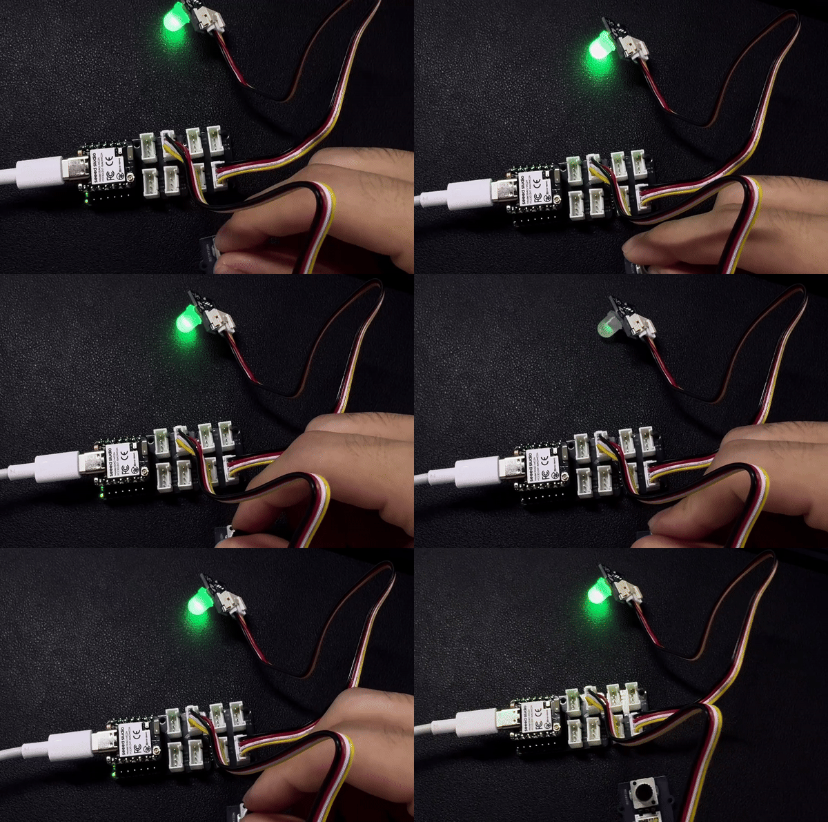
如果程序运行成功,你将看到如下运行效果。
模拟引脚
XIAO MG24(Sense)开发板配备了 12 位 ADC,可对模拟传感器数值进行高分辨率读取,这有助于我们获得更加精确的读数。
接下来,我们将选择两个传感器来体现 ADC 的特性。
硬件准备
| Seeed Studio XIAO MG24 Sense | Grove-Variable Color LED | Grove-Rotary Angle Sensor | Seeed Studio Grove Base for XIAO |
|---|---|---|---|
| |  |  |
软件实现
- analogRead 不使用 DMA
- analogRead 使用 DMA
const int analogInPin = D1;  // Analog input pin that the potentiometer is attached to
const int analogOutPin = 9;  // Analog output pin that the LED is attached to

int sensorValue = 0;  // value read from the pot
int outputValue = 0;  // value output to the PWM (analog out)

void setup() {
  Serial.begin(115200);
}

void loop() {
  sensorValue = analogRead(analogInPin);
  outputValue = map(sensorValue, 0, 4095, 0, 255);
  analogWrite(analogOutPin, outputValue);

  Serial.print("sensor = ");
  Serial.print(sensorValue);
  Serial.print("\t output = ");
  Serial.println(outputValue);
  delay(100);
}
#define ANALOG_VALUE_MIN 0     // Define the minimum analog value
#define ANALOG_VALUE_MAX 4095  // Define the maximum analog value for 12-bit ADC
#define NUM_SAMPLES 128        // Define the number of samples to collect each time

const int analogInPin = D1;            // Analog input pin that the potentiometer is attached to
const int analogOutPin = LED_BUILTIN;  // Analog output pin that the LED is attached to

// Buffers for storing samples
uint32_t analog_buffer[NUM_SAMPLES];        // Global buffer to store sampled values
uint32_t analog_buffer_local[NUM_SAMPLES];  // Local buffer to store sampled values for calculations

volatile bool data_ready_flag = false;  // Data ready flag indicating new sample data is available

void analog_samples_ready_cb();                         // Callback function called when samples are ready
void calculate_and_display_analog_level();              // Function to calculate and display the analog level
float getAverage(uint32_t *buffer, uint32_t buf_size);  // Function to compute the average of the given buffer

void setup() {
  Serial.begin(115200);
  pinMode(analogOutPin, OUTPUT);

  // Start DMA sampling, storing samples in analog_buffer, with callback on completion
  analogReadDMA(analogInPin, analog_buffer, NUM_SAMPLES, analog_samples_ready_cb);
  Serial.println("Sampling started...");
}

void loop() {
  // If data is ready, process it
  if (data_ready_flag) {
    data_ready_flag = false;
    calculate_and_display_analog_level();
  }
}

void analog_samples_ready_cb() {
  // Copy data to the local buffer in order to prevent it from overwriting
  memcpy(analog_buffer_local, analog_buffer, NUM_SAMPLES * sizeof(uint32_t));
  data_ready_flag = true;
}

void calculate_and_display_analog_level() {
  // Rolling average for smoothing the analog level
  static uint32_t rolling_average = 0u;

  // Stop sampling in order to prevent overwriting the current data
  ADC.scan_stop();

  // Get the average of the sampled values
  uint32_t analog_level = (uint32_t)getAverage(analog_buffer_local, NUM_SAMPLES);
  // Adjust the analog level
  analog_level = constrain(analog_level, ANALOG_VALUE_MIN, ANALOG_VALUE_MAX);
  // Calculate the rolling average
  rolling_average = (analog_level + rolling_average) / 2;

  // Map the current average level to brightness
  int brightness = map(rolling_average, ANALOG_VALUE_MIN, ANALOG_VALUE_MAX, 0, 255);
  if (LED_BUILTIN_ACTIVE == LOW) {
    analogWrite(analogOutPin, 255 - brightness);
  } else {
    analogWrite(analogOutPin, brightness);
  }
  // Print the average analog level and brightness output
  Serial.print("sensor = ");
  Serial.print(rolling_average);
  Serial.print("\t output = ");
  Serial.println(brightness);

  // Restart sampling
  analogReadDMA(analogInPin, analog_buffer, NUM_SAMPLES, analog_samples_ready_cb);
}

// Gets the average value of the provided samples
float getAverage(uint32_t *buffer, uint32_t buf_size) {
  if (!buffer) {
    return 0.0f;
  }

  float sum = 0.0f;
  for (uint32_t i = 0u; i < buf_size; i++) {
    sum += buffer[i];
  }
  return sum / buf_size;
}
需要注意的是,如果你想使用 DMA 来读取模拟信号,你的库版本需要大于 2.2.0。当前新版本尚未通过审核,你需要手动安装。
结果图
如果一切顺利,在上传程序后,你应该会看到如下效果。
UART
在使用 Arduino IDE 时,串口通信是许多项目中必不可少的一部分。要在 Arduino IDE 中使用串口,首先需要打开串口监视器窗口。这可以通过点击工具栏中的 Serial Monitor 图标,或者按下 Ctrl+Shift+M 快捷键来完成。
通用串口用法
一些常用的串口函数包括:
Serial.begin()-- 以指定的波特率初始化通信;Serial.print()-- 以可读格式向串口发送数据;Serial.write()-- 向串口发送二进制数据;Serial.available()-- 检查串口中是否有可读取的数据;Serial.read()-- 从串口读取一个字节的数据;Serial.flush()-- 等待正在发送的串口数据传输完成。
通过使用这些串口函数,你可以在 Arduino 开发板和计算机之间发送和接收数据,从而为创建交互式项目提供了许多可能性。
下面是一个示例程序:
void setup() {
  // initialize serial communication at 9600 bits per second:
  Serial.begin(9600);
}

void loop() {
  // send data to the serial port
  Serial.println("Hello World!");

  // read data from the serial port
  if (Serial.available() > 0) {
    // read the incoming byte:
    char incomingByte = Serial.read();
    // print the incoming byte to the serial monitor:
    Serial.print("I received: ");
    Serial.println(incomingByte);
  }

  // wait for a second before repeating the loop
  delay(1000);
}
Serial1 的使用
根据上文中 XIAO MG24(Sense) 引脚图中的具体参数,我们可以观察到有 TX 引脚和 RX 引脚。 这与串口通信有所不同,但用法也非常相似,只是需要额外添加几个参数。 所以下一步,我们将使用芯片引出的引脚进行串口通信。
#define BAUD 115200

void setup() {
    Serial1.begin(BAUD);
}

void loop() {
  if(Serial1.available() > 0)
  {
    char incominByte = Serial1.read();
    Serial1.print("I received : ");
    Serial1.println(incominByte);
  }
  delay(1000);
}
I2C
XIAO MG24(Sense) 具有一个 I2C 接口,可用于许多传感器的数据传输和解析,也可以用于驱动一些 OLED 屏幕。
硬件准备
| Seeed Studio XIAO MG24 Sense | Seeed Studio Expansion Base for XIAO with Grove OLED |
|---|---|
| |
XIAO 扩展板上的 OLED 显示屏使用 I2C 协议,并通过板载的 I2C 电路连接到 XIAO 的 I2C 接口。因此,我们可以直接将 XIAO 插到扩展板上,并通过编程在屏幕上显示内容。
软件实现
本示例介绍如何使用 Seeed Studio Expansion Base for XIAO MG24(Sense) 上的 OLED 显示屏。
步骤 1. 将 Seeed Studio XIAO MG24(Sense) 安装到扩展板上,然后连接 Type-C 线缆。
步骤 2. 安装 u8g2 库。
步骤 3. 复制代码并粘贴到 Arduino IDE 中,然后上传。
- 下载下面的 zip 文件
📄 [ZIP] smiley_face 头文件
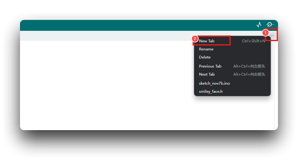
- 创建一个名为 "smiley_face. h" 的头文件,并将下载的 zip 文件中的内容复制到你创建的头文件中
#include <Arduino.h>
#include <U8g2lib.h>
#include <Wire.h>
#include "smiley_face.h"

U8G2_SSD1306_128X64_NONAME_F_HW_I2C u8g2(U8G2_R0, /* reset=*/ U8X8_PIN_NONE);

int xx = 20;
int yy = 10;

void setup() {
    u8g2.begin();
}

void loop() {
    smeil_display();
    delay(500);
}

void smeil_display() {
    const unsigned char* smileImages[] = {
        semil1, semil2, semil3, semil4, semil5,
        semil6, semil7, semil8, semil9, semil10,
        semil11, semil12, semil13, semil14, semil15,
        semil16, semil17, semil18, semil19, semil20,
        semil21, semil22, semil23, semil24, semil25,
        semil26, semil27
    };

    int delays[] = {
        40, 50, 40, 40, 40,
        40, 40, 50, 40, 40,
        40, 40, 40, 50, 40,
        40, 50, 40, 40, 50,
        40, 50, 40, 40, 50,
        50, 50, 40, 50
    };

    for (int i = 0; i < sizeof(smileImages) / sizeof(smileImages[0]); i++) {
        u8g2.firstPage();
        do {
            u8g2.drawXBMP(xx, yy, 48, 48, smileImages[i]);
        } while (u8g2.nextPage());
        delay(delays[i]);
    }
}
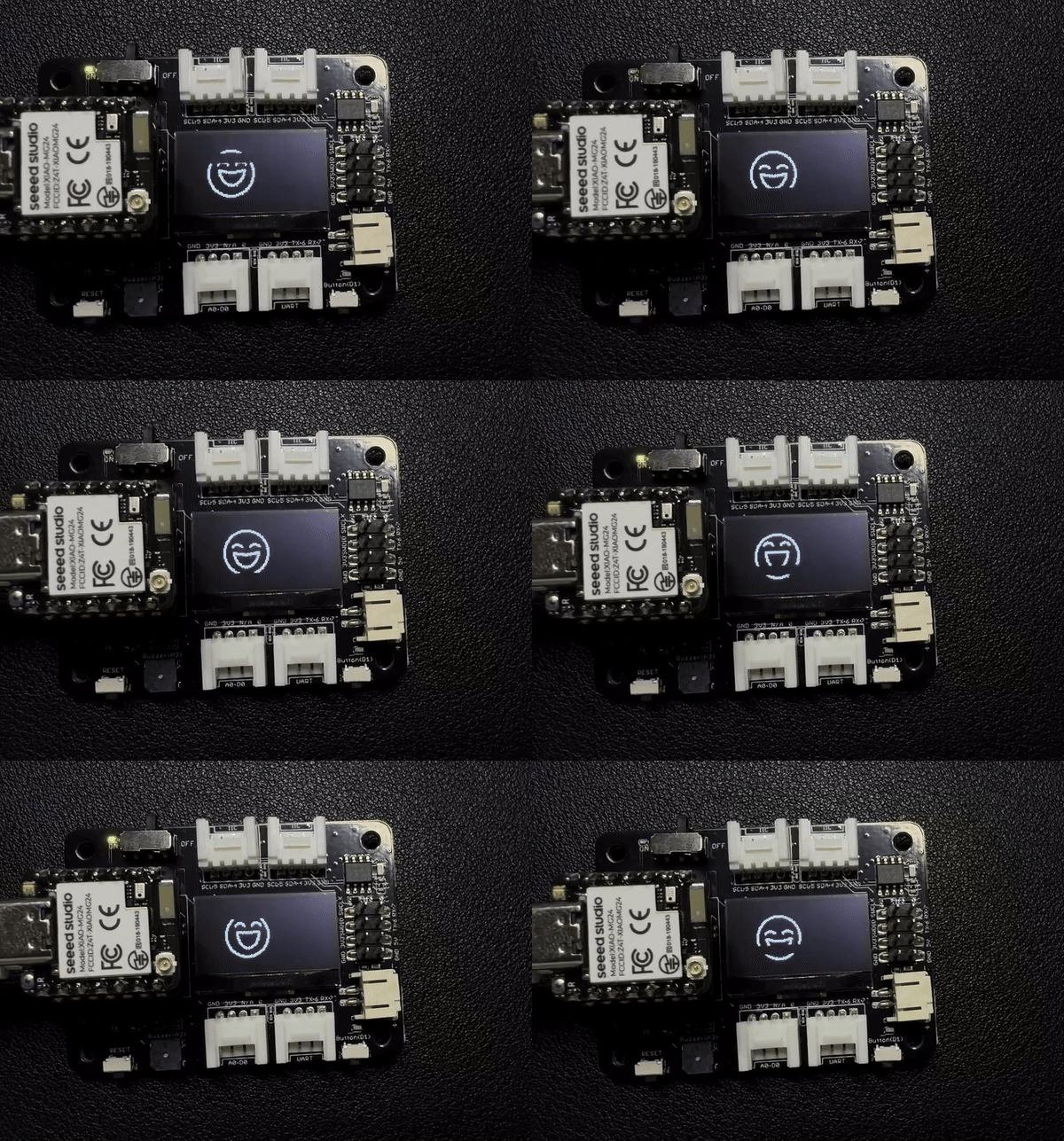
结果图
SPI
XIAO MG24(Sense) 芯片集成了多种外设,其中包括一个 SPI 接口,可用于连接外部 SPI 设备,例如闪存、显示屏、传感器等。
Arduino 库概览
基于 Waveshare 提供的 Arduino 示例程序,我们编写了一个适用于整个 XIAO 系列的 Arduino 库,你可以通过下方按钮直接跳转到该库的 Github 页面。
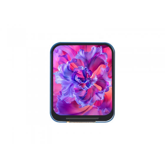
硬件准备
引脚连接
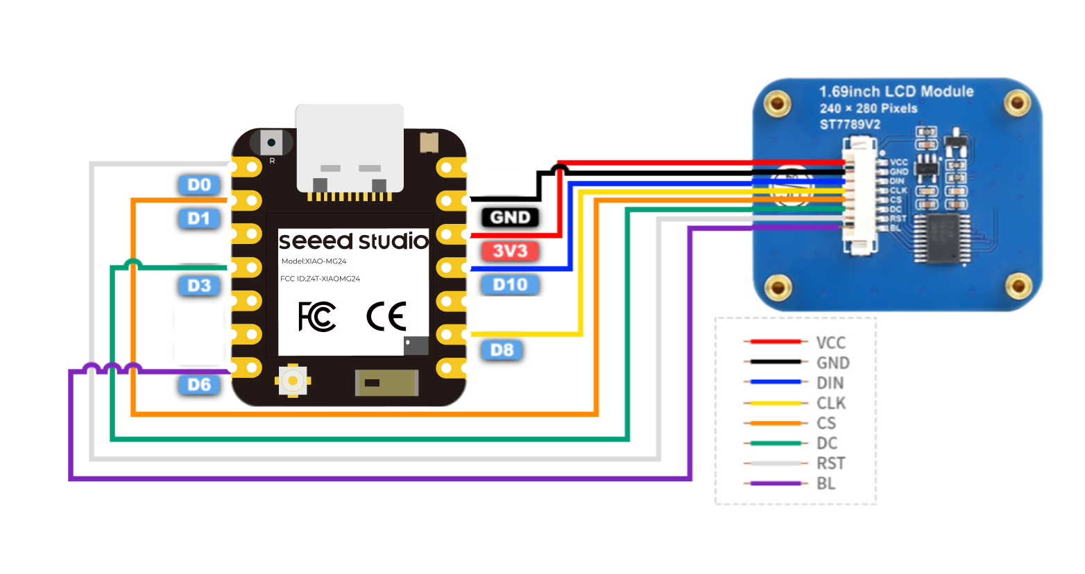
按照上述说明准备好硬件后,使用跳线将 XIAO 的 SPI 接口与 OLED 连接。请参考下图了解接线方式。
安装
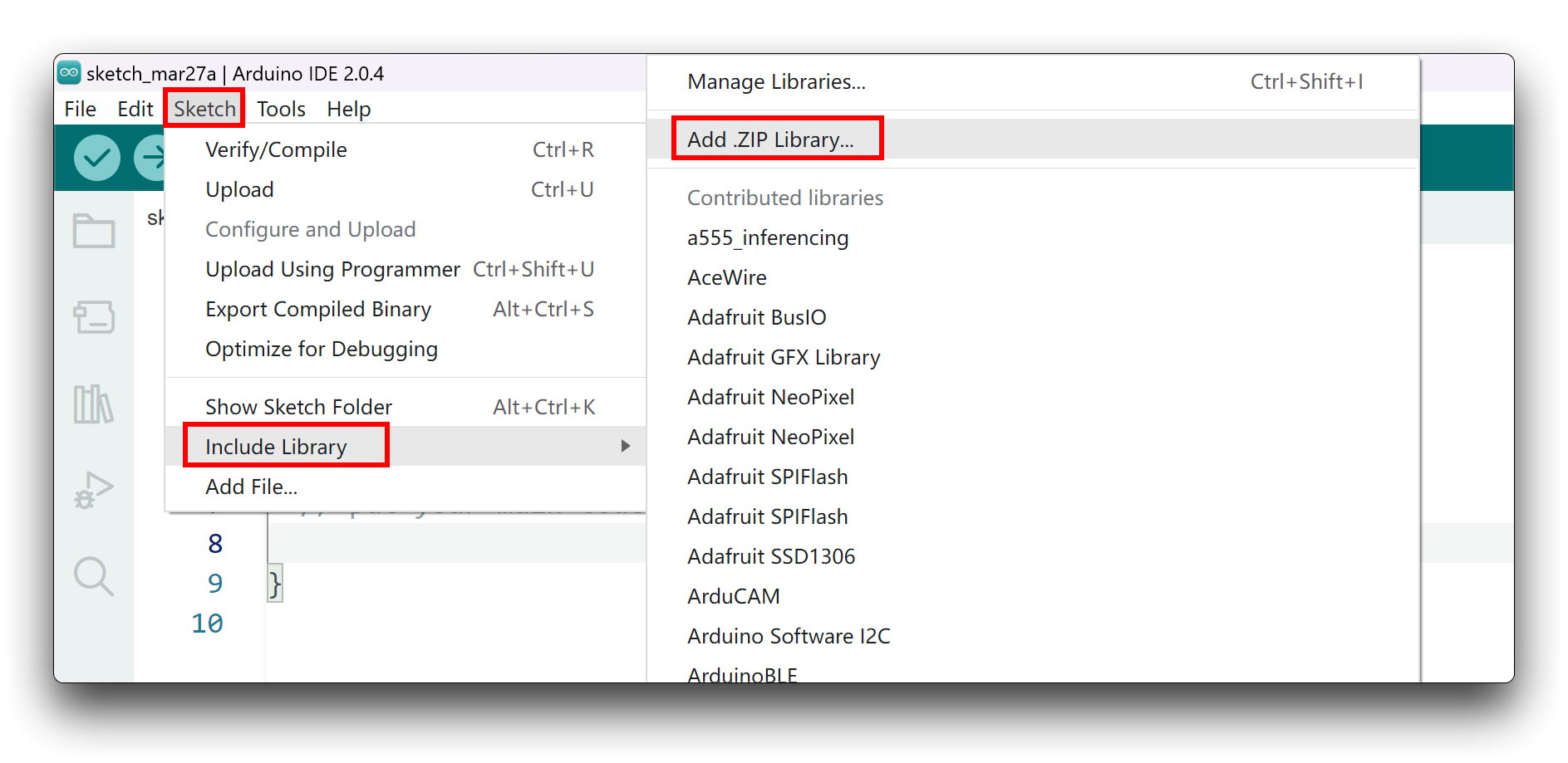
既然你已经下载了 zip 库文件,打开 Arduino IDE,点击 Sketch > Include Library > Add .ZIP Library。选择你刚刚下载的 zip 文件,如果库安装正确,你会在提示窗口中看到 Library added to your libraries,这表示库已成功安装。
软件实现
在正确下载并安装库之后,你可以在 examples 文件夹中找到两个名为 helloworld.ino 和 bgcolor.ino 的示例程序。bgcolor.ino 是一个用于显示背景颜色的示例,我们将红色设置为默认颜色。而 helloworld.ino 是一个用于显示我们公司 Logo 动画的示例,并且该示例包含了 bgcolor 示例所具有的效果。
#include <st7789v2.h>
#include "SPI.h"
#include "seeed.h"

st7789v2 Display;

void setup() {
  // put your setup code here, to run once:
  Display.SetRotate(270);
  Display.Init();
  Display.SetBacklight(100);
  Display.Clear(WHITE);
}

void loop() {
  // put your main code here, to run repeatedly:
//  Display.SetPixel(100, 100, RED);
//  Display.DrawPoint(50, 50, YELLOW, DOT_PIXEL_8X8, DOT_FILL_AROUND);

  Display.DrawImage(gImage_seeed, 20, 90, 240, 47);

  Display.DrawLine(15, 65, 65, 65, MAGENTA, DOT_PIXEL_2X2, LINE_STYLE_SOLID);
  Display.DrawLine(15, 70, 80, 70, MAGENTA, DOT_PIXEL_2X2, LINE_STYLE_SOLID);

  Display.DrawRectangle(15, 80, 265, 150, GRAY, DOT_PIXEL_2X2, DRAW_FILL_EMPTY);

  Display.DrawCircle(10, 10, 25, BLUE, DOT_PIXEL_2X2, DRAW_FILL_EMPTY);
  Display.DrawCircle(10, 10, 20, BLACK, DOT_PIXEL_2X2, DRAW_FILL_EMPTY);
  Display.DrawCircle(10, 10, 15, RED, DOT_PIXEL_2X2, DRAW_FILL_EMPTY);
  Display.DrawCircle(10, 10, 10, GREEN, DOT_PIXEL_2X2, DRAW_FILL_FULL);

  Display.DrawCircle(270, 10, 25, BLUE, DOT_PIXEL_2X2, DRAW_FILL_EMPTY);
  Display.DrawCircle(270, 10, 20, BLACK, DOT_PIXEL_2X2, DRAW_FILL_EMPTY);
  Display.DrawCircle(270, 10, 15, RED, DOT_PIXEL_2X2, DRAW_FILL_EMPTY);
  Display.DrawCircle(270, 10, 10, GREEN, DOT_PIXEL_2X2, DRAW_FILL_FULL);

  Display.DrawCircle(10, 230, 25, BLUE, DOT_PIXEL_2X2, DRAW_FILL_EMPTY);
  Display.DrawCircle(10, 230, 20, BLACK, DOT_PIXEL_2X2, DRAW_FILL_EMPTY);
  Display.DrawCircle(10, 230, 15, RED, DOT_PIXEL_2X2, DRAW_FILL_EMPTY);
  Display.DrawCircle(10, 230, 10, GREEN, DOT_PIXEL_2X2, DRAW_FILL_FULL);

  Display.DrawCircle(270, 230, 25, BLUE, DOT_PIXEL_2X2, DRAW_FILL_EMPTY);
  Display.DrawCircle(270, 230, 20, BLACK, DOT_PIXEL_2X2, DRAW_FILL_EMPTY);
  Display.DrawCircle(270, 230, 15, RED, DOT_PIXEL_2X2, DRAW_FILL_EMPTY);
  Display.DrawCircle(270, 230, 10, GREEN, DOT_PIXEL_2X2, DRAW_FILL_FULL);

  Display.DrawLine(200, 160, 265, 160, GRAYBLUE, DOT_PIXEL_2X2, LINE_STYLE_SOLID);
  Display.DrawLine(215, 165, 265, 165, GRAYBLUE, DOT_PIXEL_2X2, LINE_STYLE_SOLID);

  Display.DrawString_EN(20, 180, "By: Jason", &Font20, WHITE, BLACK);
//  Display.DrawNum(100, 220, 123456, &Font24, RED, BRED);
  Display.DrawFloatNum(100, 210, 1.00, 2, &Font16, WHITE, BLACK);
}
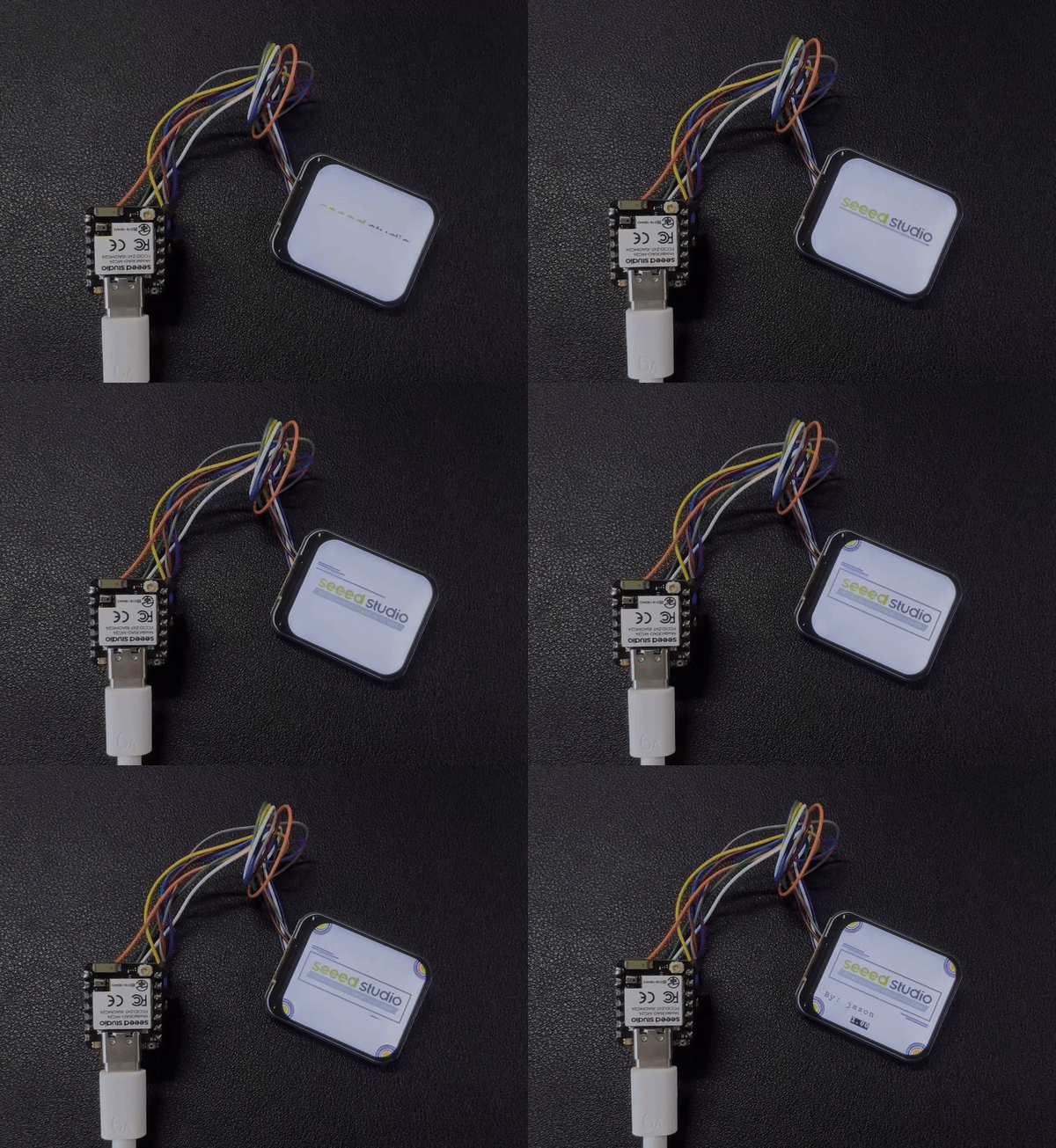
你会看到 Seeed Studio 的 Logo 在显示屏上动态显示。
总结
你已经学习了 XIAO MG24 (Sense) 引脚的基本功能。现在,让我们进一步探索其内置传感器。

技术支持与产品讨论
感谢你选择我们的产品!我们将为你提供多种支持,以确保你在使用我们产品的过程中尽可能顺利。我们提供多种交流渠道,以满足不同的偏好和需求。