
Seeed Studio XIAO nRF54L15(Sense) 入门指南
介绍
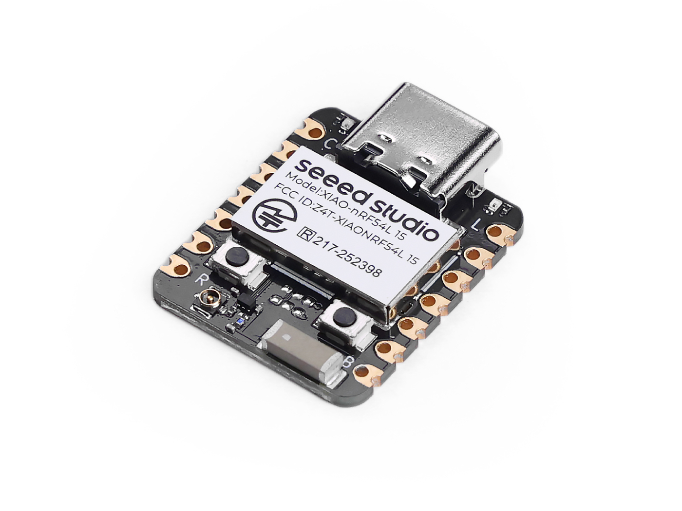
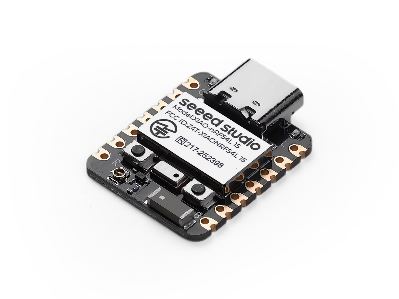
Seeed Studio XIAO nRF54L15 是一款紧凑型高性能开发板,搭载先进的 Nordic nRF54L15 芯片。这款新一代 SoC 集成了超低功耗多协议 2.4 GHz 射频,以及包含 128 MHz Arm® Cortex®-M33 处理器 和 128 MHz RISC-V 协处理器 的 MCU。它提供最高 1.5 MB NVM 和 256 KB RAM 的可扩展存储,并采用内部超低功耗设计,可显著延长电池寿命。其强大的射频支持 Bluetooth® 6.0(包括 Channel Sounding)、Matter、Thread、Zigbee,以及最高 4 Mbps 吞吐率的 2.4 GHz 私有协议模式。该开发板集成了完整的外设资源、内置 128 MHz RISC-V 协处理器,并具备 TrustZone® 隔离和加密引擎防护等高级安全特性。凭借 内置锂电池管理,XIAO nRF54L15 非常适合用于智能可穿戴设备、工业传感器和高级人机界面等紧凑、安全且高能效的物联网解决方案。
规格参数
| 项目 | XIAO nRF54L15 | XIAO nRF54L15 Sense |
|---|---|---|
| MCU | Arm Cortex-M33 128 MHz RISC-V coprocessor 128 MHz FLPR | Arm Cortex-M33 128 MHz RISC-V coprocessor 128 MHz FLPR |
| 无线连接 | Bluetooth LE 6.0(包括 Channel Sounding) | Bluetooth LE 6.0(包括 Channel Sounding) |
| 存储 | NVM 1.5 MB + RAM256 KB | NVM 1.5 MB + RAM256 KB |
| 板载传感器 | N/A | 6 DOF IMU(LSM6DS3TR-C) 麦克风 (MSM261DGT006) |
| 发射功率 | +8 dBm | +8 dBm |
| 接收灵敏度 | -96 dBm | -96 dBm |
| 重点外设 | 14-bit ADC, Global RTC | 14-bit ADC, Global RTC |
| 电源 | USB Type-C 接口供电 | USB Type-C 接口供电 |
| 工作温度 | -40 至 105°C | -40 至 105°C |
| 供电电压范围 | 3.7 至 5 V | 3.7 至 5 V |
| ESB 和 2.4 GHz 私有协议 | 最高 4 Mbps | 最高 4 Mbps |
| 防篡改检测 | YES | YES |
| Bluetooth 通道测距(channel sounding) | YES | YES |
特性
- 强大的 CPU:128 MHz Arm® Cortex®-M33 处理器,支持 DSP 指令和 FPU 浮点运算,32 位 RISC 架构,并集成 128 MHz RISC-V 协处理器。
- 超低功耗:专为超低功耗设计,可显著延长电池寿命,并集成先进的电源管理。
- 多模式无线传输:集成 2.4 GHz 多协议无线收发器,支持 Bluetooth Low Energy(包括 Channel Sounding)、802.15.4-2020、Matter、Thread、Zigbee,以及 2.4 GHz 私有模式(最高 4 Mbps)。
- 强健的安全性:具备 TrustZone® 隔离、防篡改检测以及加密引擎侧信道泄露防护等高级安全特性。
- 丰富的片上资源:最高 1.5 MB NVM 和 256 KB RAM 的可扩展存储配置,提供充足的存储空间。
- 丰富的接口:完整的外设集,包括可在 System OFF 模式下使用的新型 Global RTC、14 位 ADC 和高速串行接口。内置锂电池管理。
硬件概览
- XIAO nRF54L15
- XIAO nRF54L15 Sense
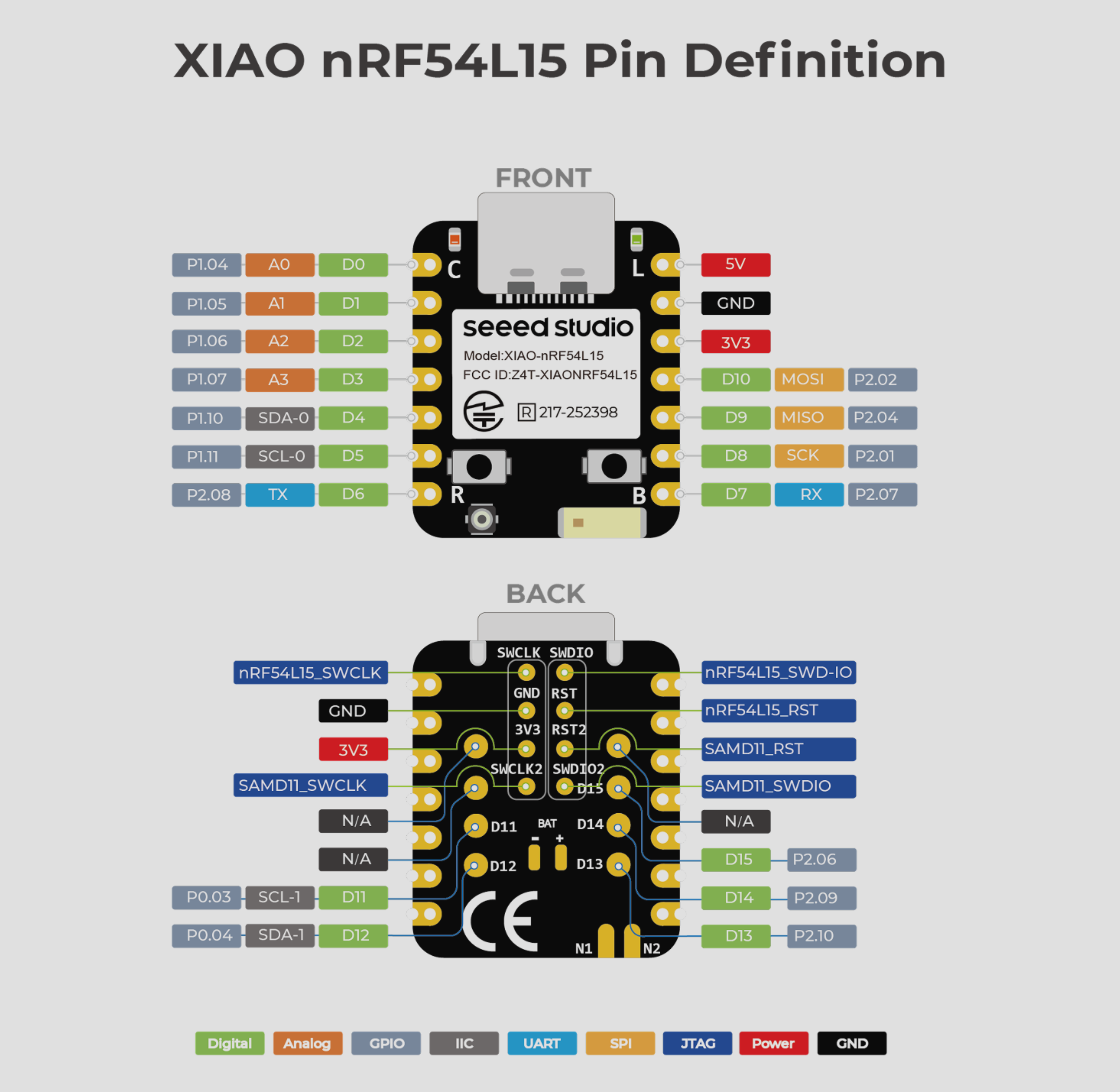
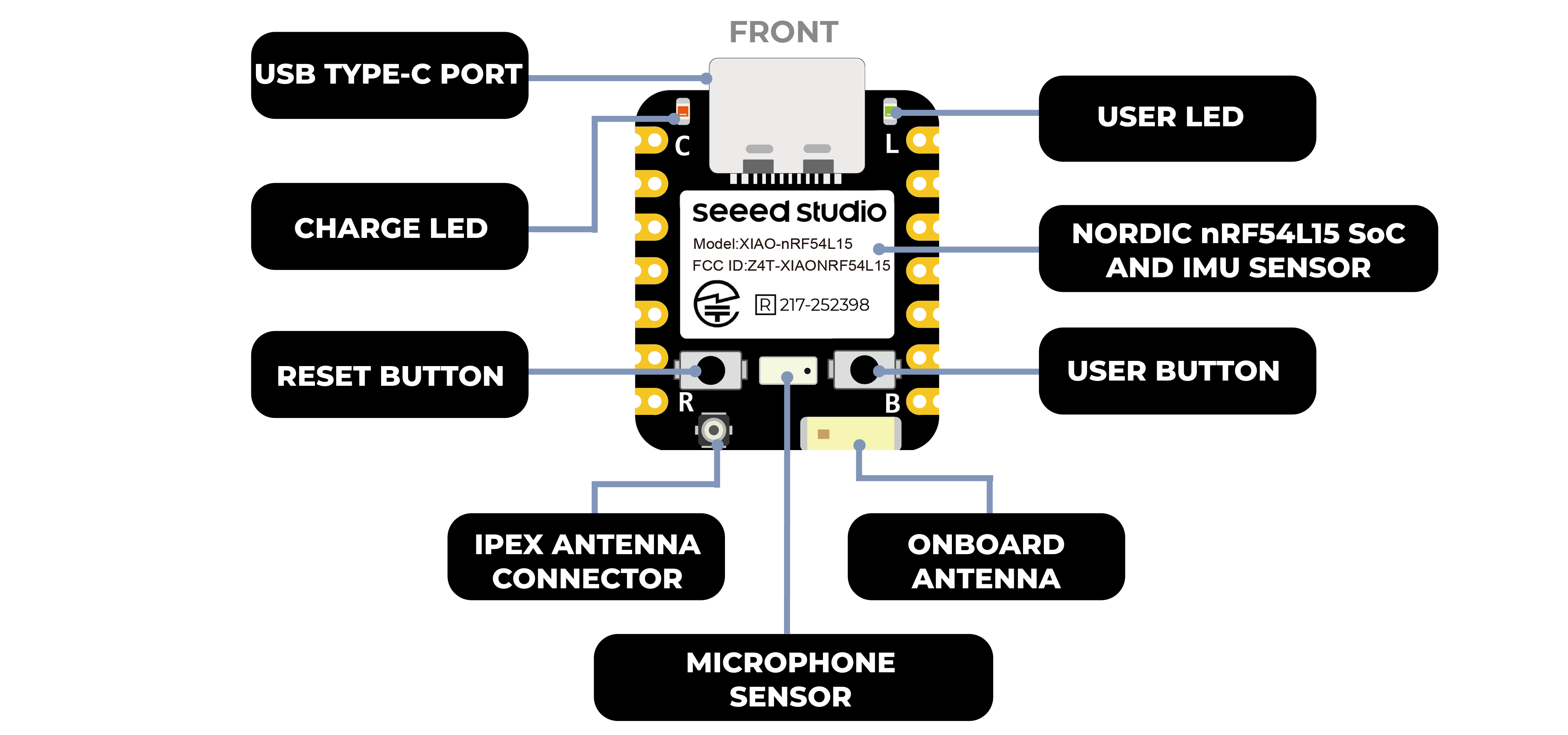
| XIAO nRF54L15 正面标注示意图 |
|---|
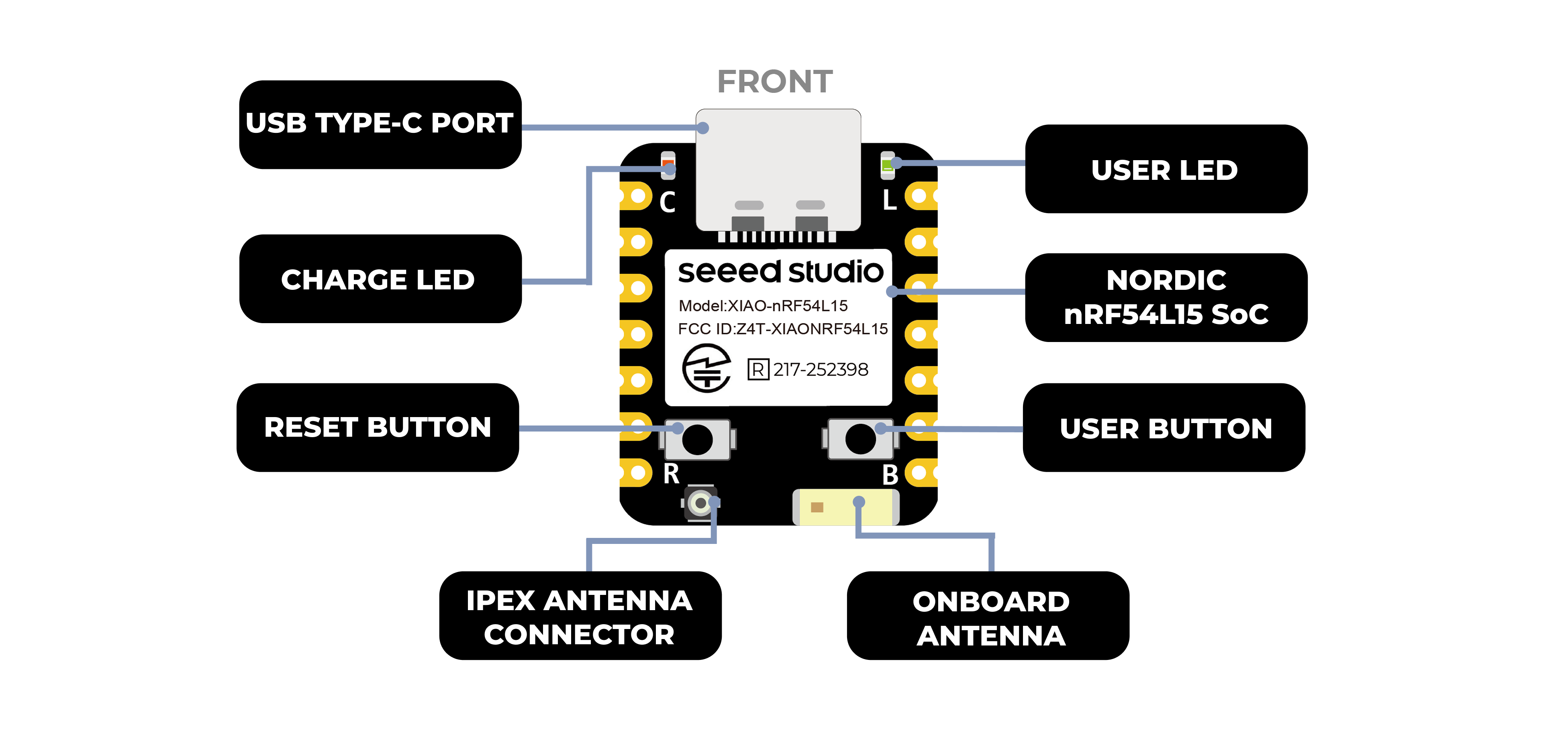 |
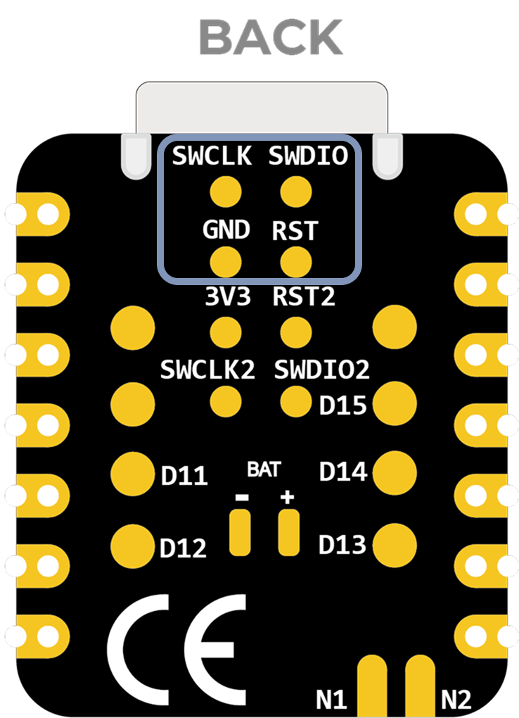
| XIAO nRF54L15 背面标注示意图 |
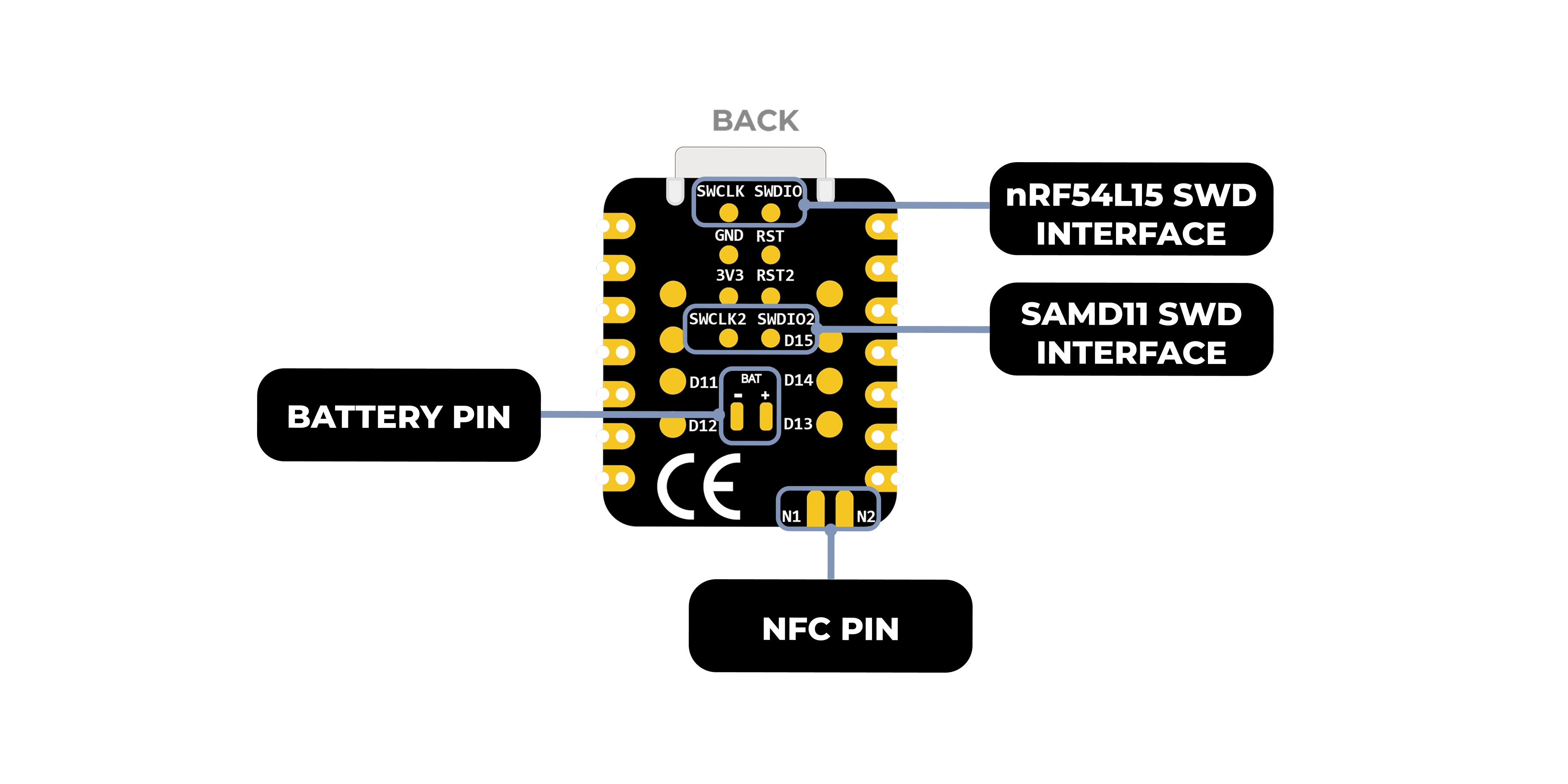 |
| XIAO nRF54L15 引脚列表 |
 |
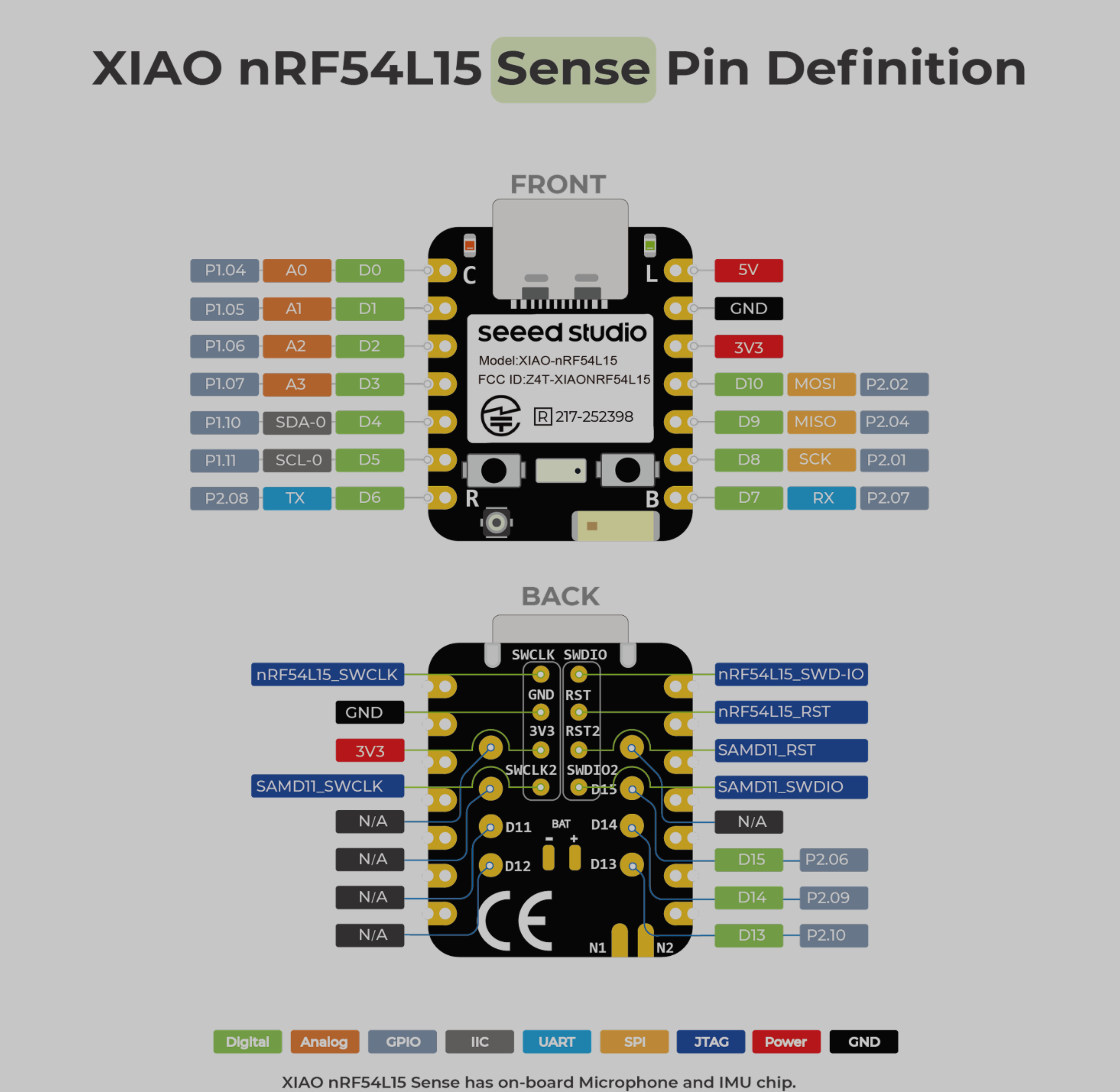
| XIAO nRF54L15 Sense 正面标注示意图 |
|---|
 |
| XIAO nRF54L15 Sense 背面标注示意图 |
|
| XIAO nRF54L15 Sense 引脚列表 |
 |
引脚映射
| XIAO 引脚 | 功能 | 芯片引脚 | 描述 |
|---|---|---|---|
| 5V | VBUS | 电源输入/输出 | |
| GND | |||
| 3V3 | 3V3_OUT | 电源输出 | |
| D0 | 模拟 | P1.04 | GPIO, ADC |
| D1 | 模拟 | P1.05 | GPIO, ADC |
| D2 | 模拟 | P1.06 | GPIO, ADC |
| D3 | 模拟 | P1.07 | GPIO, ADC |
| D4 | SDA-0 | P1.10 | GPIO, I2C 数据 |
| D5 | SCL-0 | P1.11 | GPIO, I2C 时钟 |
| D6 | TX | P2.08 | GPIO, UART 发送 |
| D7 | RX | P2.07 | GPIO, UART 接收 |
| D8 | SPI_SCK | P2.01 | GPIO, SPI 时钟 |
| D9 | SPI_MISO | P2.04 | GPIO, SPI 数据 |
| D10 | SPI_MOSI | P2.02 | GPIO, SPI 数据 |
| D11 | SCL-1 | P0.03 | GPIO, I2C |
| D12 | SDA-1 | P0.04 | GPIO,I2C |
| D13 | GPIO | P2.10 | GPIO |
| D14 | GPIO | P2.09 | GPIO |
| D15 | GPIO | P2.06 | GPIO |
| nRF54L15_SWCLK | SWDCLK | JTAG | |
| nRF54L15_SWD-IO | SWDIO | JTAG | |
| nRF54L15_RST | RST | JTAG | |
| SAMD11_SWCLK | PA30 | JTAG | |
| SAMD11_SWDIO | PA31 | JTAG | |
| SAMD11_RST | RST2 | JTAG | |
| NFC1 | P1.02 | NRF | |
| NFC2 | P1.03 | NRF | |
| Reset | nRF54_RESET | EN | |
| USER KEY | P0.00 | 用户按键 | |
| RF Switch Port Select | P2.05 | 切换板载天线 | |
| RF Switch Power | P2.03 | 电源 | |
| AIN7_VBAT | P1.14 | 读取电池电压值 | |
| CHARGE_LED | charge_LED | CHG-LED_Red | |
| USER_LED | P2.00 | 用户指示灯 |
nRFConnect SDK 使用
nRF Connect SDK(NCS)是 Nordic Semiconductor 推出的可扩展、统一的软件开发套件,专门用于为基于 Nordic nRF52、nRF53、nRF54、nRF70 和 nRF91 系列的无线设备构建低功耗无线应用。
NCS 提供了丰富的现成示例应用、协议栈、库和硬件驱动生态系统,旨在简化开发流程并加速产品上市。其模块化和可配置的特性,使开发者既可以为内存受限的设备构建尺寸优化的软件,也可以为更高级和更复杂的应用实现强大的功能。NCS 是一个托管在 GitHub 上的开源项目,并为 Visual Studio Code 等集成开发环境提供了出色的支持。
在 VSCode 上使用 nRF Connect SDK
提前安装 nRF Connect SDK 相关知识
本文档详细说明了如何在 Windows 11 电脑上安装 nRF Connect SDK 开发环境。以下是需要安装的工具概览
-
安装 VS Studio Code
-
nRF 命令行工具
-
nRF Connect for Desktop
-
Git
-
Ninja
ninja --version
- CMake
cmake --version
- Zephyr SDK
west --version
- nRF Connect SDK
- VSCode nRF Connect 插件
如果你已经在电脑上预先安装了这些工具,可以通过以下命令检查你的工具版本号
VScode 配置开发板并构建烧录文件
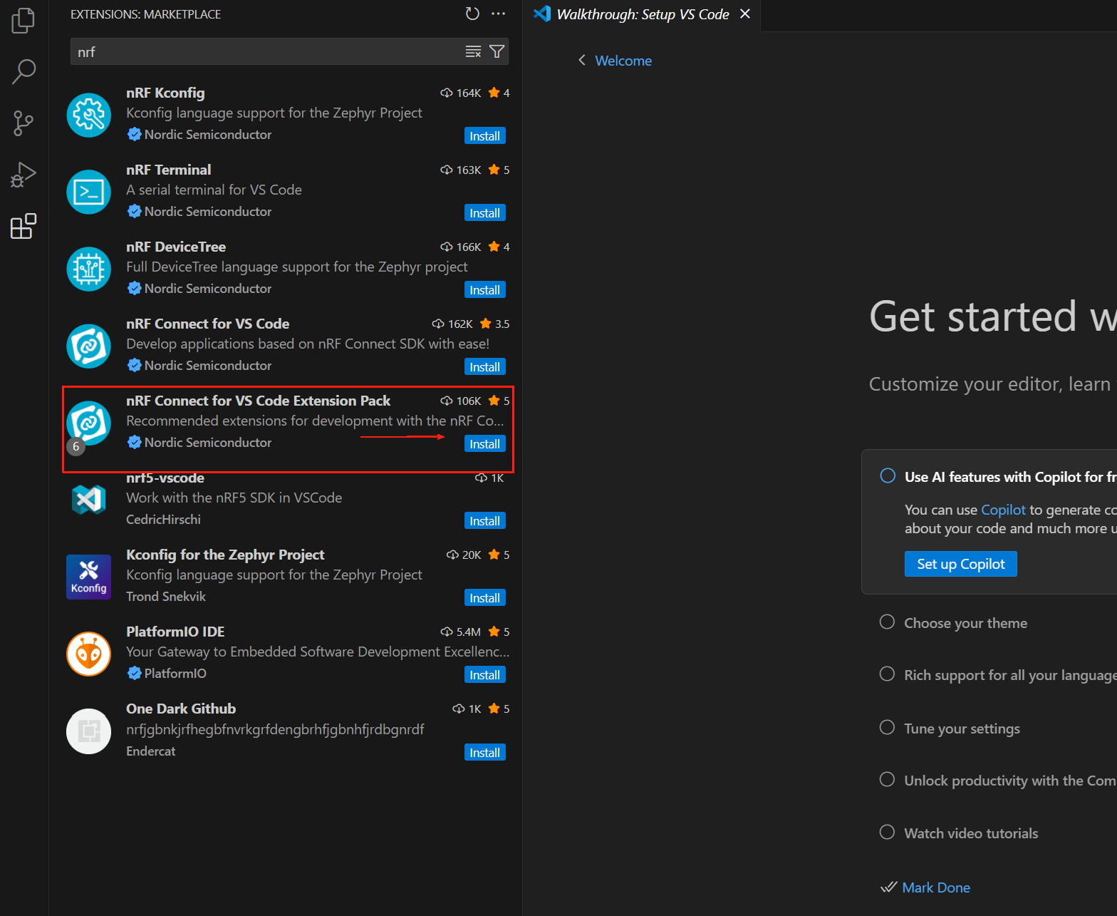
打开 VS Code,在插件中心搜索 nRF Connect for VS Code Extension Pack。该插件包会自动安装 nRF Connect 所需的其他 VS Code 插件。
nRF Connect for VS Code 扩展使开发者能够利用流行的 Visual Studio Code 集成开发环境(VS Code IDE)来开发、构建、调试和部署基于 Nordic nRF Connect SDK(软件开发套件)的嵌入式应用。该扩展包含诸多实用开发工具,例如编译器接口、链接器、完整构建系统、支持 RTOS 的调试器、与 nRF Connect SDK 的无缝对接、设备树可视化编辑器以及集成串口终端。
nRF Connect for VS Code 扩展包包括以下组件:
- nRF Connect for VS Code:主扩展,包含构建系统与 nRF Connect SDK 之间的接口,以及用于管理 nRF Connect SDK 版本和工具链的接口。
- nRF DeviceTree:提供设备树语言支持和设备树可视化编辑器。
- nRF Kconfig:提供 Kconfig 语言支持。
- nRF Terminal:串口和 RTT 终端。
- Microsoft C/C++:为 C/C++ 添加语言支持,包括 IntelliSense 功能。
- CMake:CMake 语言支持。
- GNU Linker Mapping Files:链接器映射文件支持。 我们可以通过该扩展下载任意所需版本的 nRF Connect SDK 及其工具链。完整的 nRF Connect for VS Code 文档可在 https://docs.nordicsemi.com/bundle/nrf-connect-vscode/page/index.html 查阅。
安装工具链
工具链是一组协同工作的工具集合,用于构建 nRF Connect SDK 应用,包括汇编器、编译器、链接器和 CMake 组件。 首次打开 nRF Connect for VS Code 时,系统会提示你安装工具链。如果扩展未检测到电脑上已安装的任何工具链,通常就会出现此提示。 点击 Install Toolchain,将列出可在电脑上下载和安装的工具链版本列表。选择与你计划使用的 nRF Connect SDK 版本相匹配的工具链版本。我们始终建议使用最新的 nRF Connect SDK 标记版本。
默认情况下,nRF Connect for VS Code 只显示工具链的 Released 选项卡(即稳定版本)。如果你正在评估新特性,并希望使用 Preview 选项卡或其他类型的选项卡(例如 Customer Sampling -cs),请点击如下所示的 "Show all toolchain versions":
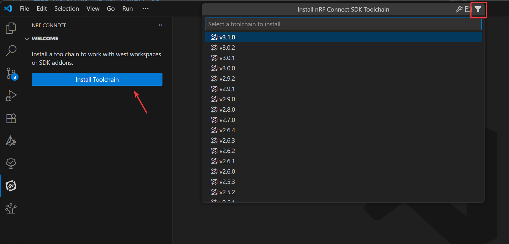
此处的 ToolChain 版本需为 3.0.1 或更高
安装 nRF Connect SDK
在 VS Code 的 nRF Connect 扩展中,点击 Manage SDK。通过 Manage SDK 菜单,我们可以安装或卸载 nRF Connect SDK 版本。由于这是我们第一次使用该扩展,界面中只会显示两个选项。
点击 Install SDK 将列出所有可下载并在本地安装的 nRF Connect SDK 版本。选择项目开发所需的 nRF Connect SDK 版本。
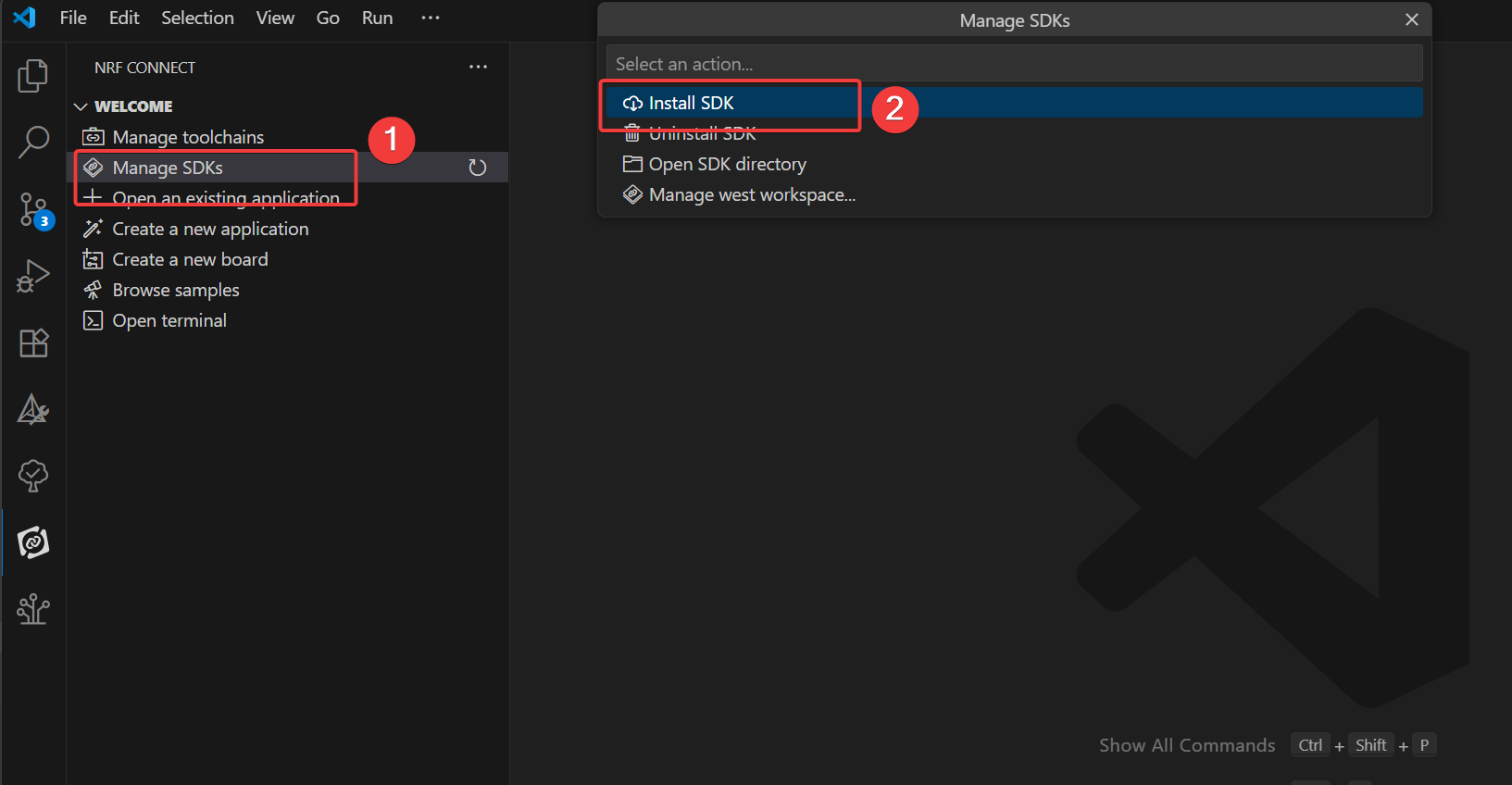
如果你已经在 VS Code 中打开了 SDK 文件夹,那么你将看到 Manage west workspace,而不是 Manage SDK 菜单选项。要解决此问题,请在 VS Code 中打开另一个窗口或文件夹。
此处的 nRF Connect SDK 版本需为 3.0.1 或更高
如果你没有看到这两个选项中的任意一个,请确保你安装的是最新版本的 nRF Connect for VS Code 扩展包。 需要特别注意的是,nRF Connect SDK 与 IDE 无关,这意味着你可以选择使用任意 IDE,或者完全不使用 IDE。nRF Connect SDK 可以通过 https://www.nordicsemi.com/Products/Development-tools/nRF-Util(nrfutil)命令行接口(CLI)下载并安装 nRF Connect。然而,我们强烈建议在 VS Code 中使用我们的 nRF Connect for VS Code 扩展,因为它不仅集成了便捷的图形用户界面(GUI)和高效的命令行界面(CLI),还包含大量能够极大简化固件开发的功能。将其他 IDE 配置为与 nRF Connect SDK 协同工作需要额外的手动步骤,超出了本课程的范围。
创建用户程序
在本练习中,我们将基于 blinky 示例编写一个简单应用,用于控制开发板上的 LED 闪烁。该方法同样适用于所有受支持的 Nordic Semiconductor 开发板(nRF54、nRF53、nRF52、nRF70 或 nRF91 系列)。目标是确保构建和烧录该示例所需的所有工具均已正确配置。重点在于学习如何创建应用、构建应用,并使用 “Copy Example” 模板将其烧录到 Nordic 芯片开发板上!
- 在 VS Code 中,点击 nRF Connect 扩展图标。在 Welcome 视图中,点击 Create New Application。
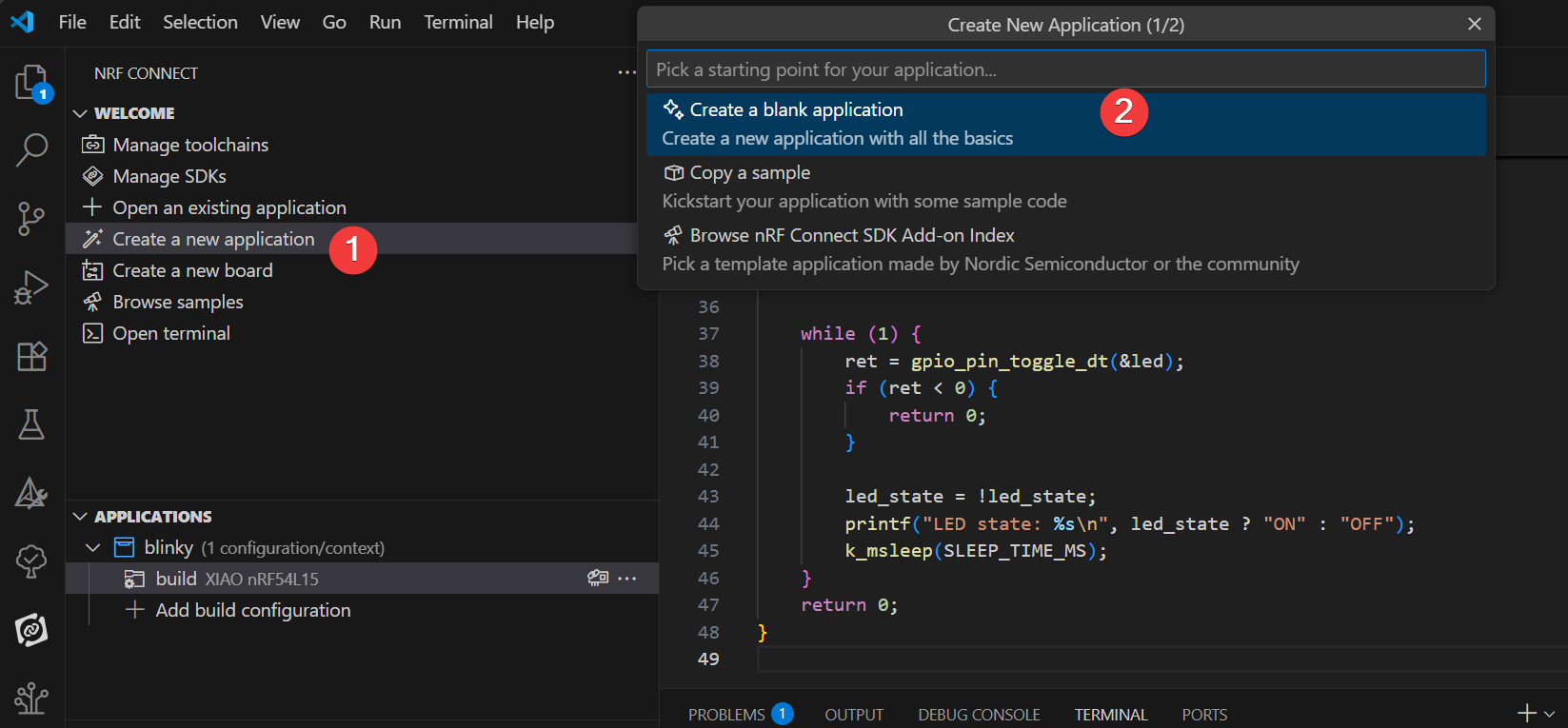
- 在搜索栏中输入 blinky,并选择第二个 Blinky 示例(路径 zephyr/samples/basic/blinky),如下图所示。
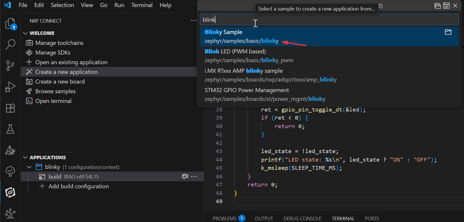
Blinky 示例会让开发板上的 LED1 持续闪烁。 我们的第一个应用将基于 Blinky 示例。Blinky 示例源自 nRF Connect SDK 中的 Zephyr 模板模块,因此你会在示例路径中看到 zephyr 名称:zephyr\samples\basic\blinky。
添加 XIAO nRF54L15 开发板
首先,从 GitHub 链接克隆仓库git clone https://github.com/Seeed-Studio/platform-seeedboards.git 到你偏好的本地文件夹。克隆完成后,进入 platform-seeedboards/zephyr/ 目录。记住这个 zephyr 文件夹路径;
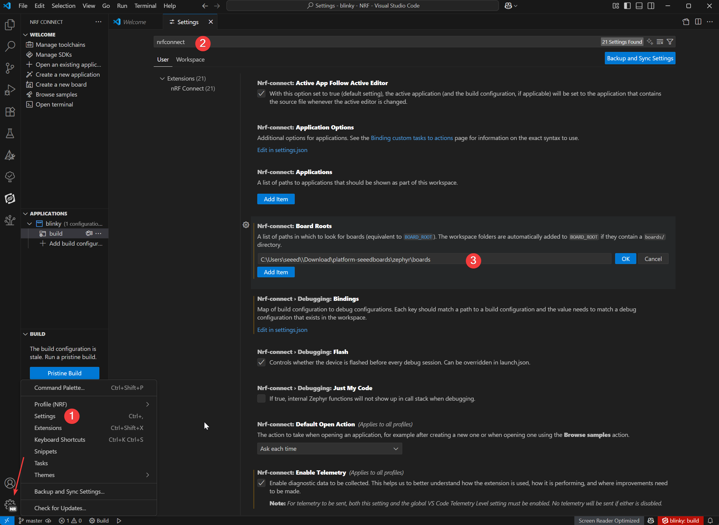
要在 VS Code 中为 nRF Connect 配置你的开发板,可以按照以下步骤进行:
-
打开 VS Code 并进入 Settings。
-
在搜索框中输入 nRF Connect。
-
找到 Board Roots 设置项并点击 Edit in settings.json。
-
将下载的 XIAO nRF54L15 开发板文件中的
zephyr路径添加到 boardRoots 数组中。
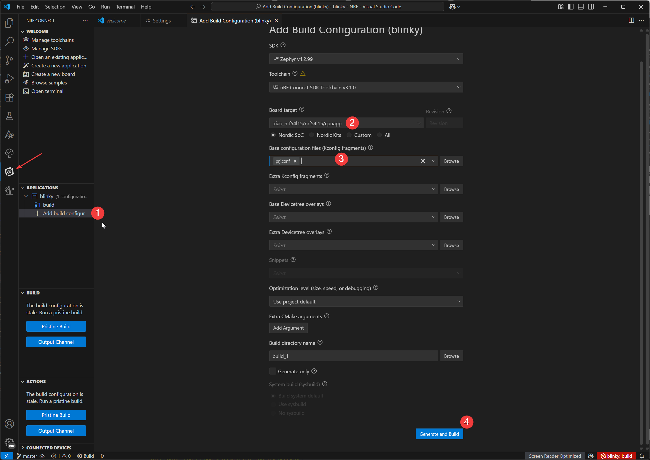
-
在应用视图中,点击应用名称下方的 Add Build Configuration。
-
我们可以在 Board target 中选择 XIAO nRF54L15 的型号,在 Base configuration files 中选择默认的 prj.config 文件,最后点击
Generate and Build来构建文件。
下载烧录插件
- Window
- Mac OS
附加插件:
在 Windows 上,我们将使用 Chocolatey 包管理器来安装 OpenOCD。
1. 打开 PowerShell(以管理员身份运行):
- 在 Windows 搜索栏中输入 "PowerShell"。
- 右键点击 "Windows PowerShell" 并选择 "Run as administrator"。
2. 检查 PowerShell 执行策略:
- 输入
Get-ExecutionPolicy并按回车。 - 输入
Get-ExecutionPolicy -List并按回车。
3. 安装 Chocolatey:
- 粘贴并运行以下命令:
Set-ExecutionPolicy Bypass -Scope Process -Force; [System.Net.ServicePointManager]::SecurityProtocol = [System.Net.ServicePointManager]::SecurityProtocol -bor 3072; iex ((New-Object System.Net.WebClient).DownloadString('https://community.chocolatey.org/install.ps1'))
该命令会在当前 PowerShell 会话中绕过执行策略并安装 Chocolatey。安装完成后,关闭并重新打开 PowerShell 窗口(仍需以管理员身份运行)。
4. 安装 OpenOCD:
- 在新的 PowerShell 窗口中(以管理员身份),输入:
choco install openocd
5. 验证 OpenOCD 安装:
-
输入
Get-Command openocd并按回车。 -
如果安装成功,该命令会显示 openocd.exe 的路径。
附加插件:
在 macOS 上,我们将使用 Homebrew 包管理器来安装所需工具。
1. 安装 Homebrew(如果尚未安装):
-
打开 Terminal.app。
-
运行以下命令:
/bin/bash -c "$(curl -fsSL https://raw.githubusercontent.com/Homebrew/install/HEAD/install.sh)"
- 按照屏幕提示操作;你可能需要输入 macOS 用户密码。安装完成后,根据终端提示运行命令,将 Homebrew 添加到你的 PATH 环境变量中
(例如,eval "$(/opt/homebrew/bin/brew shellenv)")。然后关闭并重新打开终端。
2. 安装 Ccache:
在终端中输入:
brew install ccache
3. 安装 OpenOCD:
在终端中输入:
brew install openocd
4. 验证 OpenOCD 安装::
-
输入
which openocd并按回车。 -
如果安装成功,该命令会显示
openocd可执行文件的路径。
West Flash 烧录程序
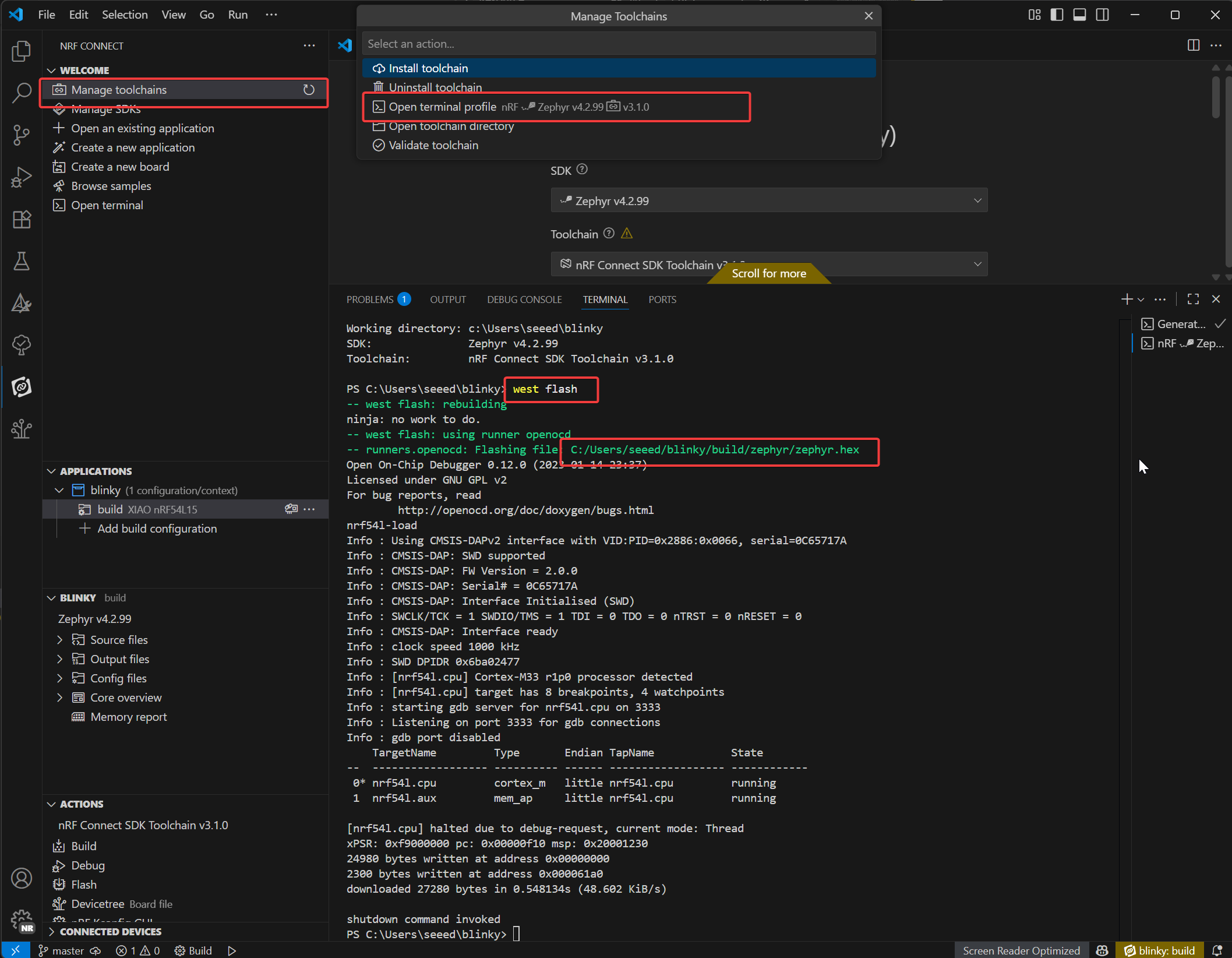
-
打开 nRF 终端
-
只需输入
west flash命令即可烧录你的设备。要烧录你的设备,只需输入 west flash 命令。红色高亮的路径表示你编译生成的 .elf 文件所在位置。你可以使用同一路径找到对应的 .hex 文件,该文件适用于使用 J-Link 调试器进行编程。
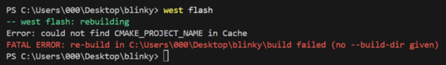
如果出现 west flash 错误,说明与 VS Code 中的 CMake 插件发生冲突,你需要移除 CMake 插件。
当我们在 Seeed Studio XIAO nRF54L15 Sense 中成功烧录程序后,你可以看到开发板上的用户指示灯以绿色不停闪烁,如果你手中的板子也呈现相同的效果,就说明你已经成功上手了!🎊
Blinky 程序讲解
/*
 * Copyright (c) 2016 Intel Corporation
 *
 * SPDX-License-Identifier: Apache-2.0
 */

#include <stdio.h>
#include <zephyr/kernel.h>
#include <zephyr/drivers/gpio.h>

/* 1000 msec = 1 sec */
#define SLEEP_TIME_MS   1000

/* The devicetree node identifier for the "led0" alias. */
#define LED0_NODE DT_ALIAS(led0)

/*
 * A build error on this line means your board is unsupported.
 * See the sample documentation for information on how to fix this.
 */
static const struct gpio_dt_spec led = GPIO_DT_SPEC_GET(LED0_NODE, gpios);

int main(void)
{
int ret;
bool led_state = true;

if (!gpio_is_ready_dt(&led)) {
  return 0;
}

ret = gpio_pin_configure_dt(&led, GPIO_OUTPUT_ACTIVE);
if (ret < 0) {
  return 0;
}

while (1) {
  ret = gpio_pin_toggle_dt(&led);
  if (ret < 0) {
    return 0;
  }

  led_state = !led_state;
  printf("LED state: %s\n", led_state ? "ON" : "OFF");
  k_msleep(SLEEP_TIME_MS);
}
return 0;
}
LED 设备定义:
#define LED0_NODE DT_ALIAS(led0): 获取 "led0" 别名对应的设备树节点标识符,从而以与硬件无关的方式引用该 LED。static const struct gpio_dt_spec led = GPIO_DT_SPEC_GET(LED0_NODE, gpios): 使用设备树节点创建一个 GPIO 规范结构体(led),其中包含该 LED 的硬件细节(引脚、端口)。如果在这里出现构建错误,说明硬件不受支持。
main() 函数初始化:
-
变量设置:
int ret: 用于存储函数返回值,以检查操作是否成功。bool led_state = true: 跟踪 LED 状态(初始化为“ON”)。
-
GPIO 就绪检查:
if (!gpio_is_ready_dt(&led)) { return 0; }: 验证 LED 的 GPIO 硬件是否就绪(例如驱动是否已加载)。如果未就绪则退出。
-
GPIO 配置:
ret = gpio_pin_configure_dt(&led, GPIO_OUTPUT_ACTIVE): 将 LED 的 GPIO 引脚配置为有效高输出。- 如果失败(
ret < 0)则退出,以避免无效操作。
主循环:
在无限 while (1) 循环中运行,以周期性地切换 LED:
-
切换 LED 状态:
ret = gpio_pin_toggle_dt(&led): 翻转 LED 的 GPIO 输出(ON ↔ OFF)。失败则退出。
-
更新状态跟踪:
led_state = !led_state: 使软件状态标志与硬件状态保持同步。
-
日志与延时:
printf("LED state: %s\n", led_state ? "ON" : "OFF"): 通过串口输出当前 LED 状态。k_msleep(SLEEP_TIME_MS): 使用 Zephyr 的 RTOS 延时函数暂停 1000ms(1 秒),以控制闪烁频率。
深入了解 nRF Connect SDK 内部机制
如果你想更深入地了解 nRF Connect SDK 的内部原理,可以参考以下课程:
恢复出厂设置
对于 XIAO nRF54L15 开发板,我们提供了一个出厂重置脚本,用于在开发板处于异常状态时进行恢复(例如由于内部 NVM 写保护导致无法上传程序)。该脚本会对 Flash 执行整体擦除,并烧录出厂固件。
位置 脚本位于 scripts/factory_reset/ 目录中。 用法 脚本会自动创建并管理本地 Python 虚拟环境以安装必要工具,因此可以开箱即用。
Window
- 对于 Windows:进入 scripts/factory_reset 目录并运行:
.\factory_reset.bat
Linux-MacOS
- 对于 Linux 和 macOS:进入 scripts/factory_reset 目录并运行:
bash factory_reset.sh
无线切换模式
此示例演示如何控制 Seeed Studio XIAO nRF54L15 上的射频开关,在板载之间切换
::: 以下示例适用于 PlatformIO 和 nRF Connect SDK。它可以直接在 PlatformIO 中使用,而 SDK 需要手动添加文件。请参考此链接 :::
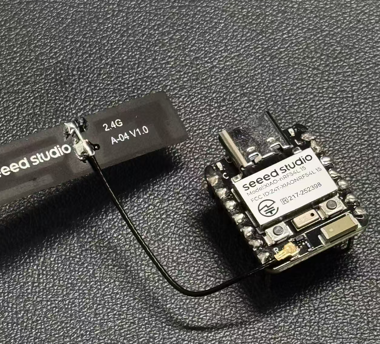
外置天线
-
陶瓷天线和外置天线。
-
按下用户按钮(SW0)在陶瓷天线和外置天线之间切换。
-
用户 LED 指示当前天线选择(LED 亮为外置天线,LED 灭为陶瓷天线)。
-
启动时的默认天线可以通过 prj.conf 进行配置。
/*
 * Copyright (c) 2024 Seeed Technology Co.,Ltd
 *
 * SPDX-License-Identifier: Apache-2.0
 */

#include <zephyr/kernel.h>
#include <zephyr/device.h>
#include <zephyr/drivers/gpio.h>
#include <zephyr/logging/log.h>
#include <zephyr/devicetree.h>

LOG_MODULE_REGISTER(app, CONFIG_LOG_DEFAULT_LEVEL);

/* Devicetree node identifiers */
#define RFSW_REGULATOR_NODE DT_NODELABEL(rfsw_ctl)
#define SW0_NODE            DT_ALIAS(sw0)
#define LED0_NODE           DT_ALIAS(led0)

/* State variables */
static uint8_t onoff_flag = 0;
#ifdef CONFIG_DEFAULT_ANTENNA_EXTERNAL
static bool is_external_antenna = true;
#else
static bool is_external_antenna = false;
#endif

/* GPIO device specs */
/* Manually build gpio_dt_spec for rfsw_ctl */
static const struct gpio_dt_spec rfsw_gpio = {
	.port = DEVICE_DT_GET(DT_GPIO_CTLR(RFSW_REGULATOR_NODE, enable_gpios)),
	.pin = DT_GPIO_PIN(RFSW_REGULATOR_NODE, enable_gpios),
	.dt_flags = DT_GPIO_FLAGS(RFSW_REGULATOR_NODE, enable_gpios),
};
static const struct gpio_dt_spec button = GPIO_DT_SPEC_GET(SW0_NODE, gpios);
static const struct gpio_dt_spec led = GPIO_DT_SPEC_GET(LED0_NODE, gpios);

/* Button callback data */
static struct gpio_callback button_cb_data;

/* Forward declarations */
void button_pressed(const struct device *dev, struct gpio_callback *cb, uint32_t pins);
void update_antenna_switch(void);

/* Function to update antenna switch and LED */
void update_antenna_switch(void)
{
    int ret;
    is_external_antenna = !is_external_antenna;

    if (is_external_antenna) {
        /* Switch to external antenna */
        LOG_INF("Switching to External Antenna");

        // To get a physical high level (Inactive state), we need to set the logic to '0'
        ret = gpio_pin_set_dt(&rfsw_gpio, 0);
        if (ret < 0) {
            LOG_ERR("Error setting rfsw-ctl to physical HIGH: %d\n", ret);
        }

        // Turn on the LED (set 0 for on)
        ret = gpio_pin_set_dt(&led, 0);
        if (ret < 0) {
            LOG_ERR("Error turning on LED: %d\n", ret);
        }

    } else {
        /* Switch back to ceramic antenna */
        LOG_INF("Switching to Ceramic Antenna");

        // To get a physical low level (Active state), we need to set the logic to '1'
        ret = gpio_pin_set_dt(&rfsw_gpio, 1);
        if (ret < 0) {
            LOG_ERR("Error setting rfsw-ctl to physical LOW: %d\n", ret);
        }

        // Turn off the LED (set 1 for off)
        ret = gpio_pin_set_dt(&led, 1);
        if (ret < 0) {
            LOG_ERR("Error turning off LED: %d\n", ret);
        }
    }
}

/* Button pressed callback function */
void button_pressed(const struct device *dev, struct gpio_callback *cb,
                    uint32_t pins)
{
    update_antenna_switch();
}

int main(void)
{
    int ret;

    /* Check if GPIO devices are ready */
    if (!gpio_is_ready_dt(&rfsw_gpio)) {
        LOG_ERR("RF switch control GPIO not ready\n");
        return -1;
    }
    if (!gpio_is_ready_dt(&button)) {
        LOG_ERR("Button GPIO not ready\n");
        return -1;
    }
    if (!gpio_is_ready_dt(&led)) {
        LOG_ERR("LED GPIO not ready\n");
        return -1;
    }

    /* Configure GPIO pins */
    ret = gpio_pin_configure_dt(&rfsw_gpio, GPIO_OUTPUT);
    if (ret < 0) {
        LOG_ERR("Error configuring rfsw-ctl: %d\n", ret);
        return ret;
    }

    /* Configure LED as output, default off */
    ret = gpio_pin_configure_dt(&led, GPIO_OUTPUT_ACTIVE);
    if (ret < 0) {
        LOG_ERR("Error configuring LED: %d\n", ret);
        return ret;
    }

    /* Set initial LED state based on antenna selection */
    if (is_external_antenna) {
        // External antenna
        LOG_INF("Initial state: External Antenna");
        ret = gpio_pin_set_dt(&rfsw_gpio, 0);
        if (ret < 0) {
            LOG_ERR("Error setting rfsw-ctl to physical HIGH: %d\n", ret);
        }
        ret = gpio_pin_set_dt(&led, 0);  // Turn on LED
        if (ret < 0) {
            LOG_ERR("Error turning on LED: %d\n", ret);
        }
    } else {
        // Ceramic antenna
        LOG_INF("Initial state: Ceramic Antenna");
        ret = gpio_pin_set_dt(&rfsw_gpio, 1);
        if (ret < 0) {
            LOG_ERR("Error setting rfsw-ctl to physical LOW: %d\n", ret);
        }
        ret = gpio_pin_set_dt(&led, 1);  // Turn off LED
        if (ret < 0) {
            LOG_ERR("Error turning off LED: %d\n", ret);
        }
    }

    /* Configure button as input */
    ret = gpio_pin_configure_dt(&button, GPIO_INPUT);
    if (ret < 0) {
        LOG_ERR("Error configuring button: %d\n", ret);
        return ret;
    }

    /* Configure button interrupt */
    ret = gpio_pin_interrupt_configure_dt(&button, GPIO_INT_EDGE_TO_ACTIVE);
    if (ret < 0) {
        LOG_ERR("Error configuring button interrupt: %d\n", ret);
        return ret;
    }

    /* Initialize button callback */
    gpio_init_callback(&button_cb_data, button_pressed, BIT(button.pin));
    gpio_add_callback(button.port, &button_cb_data);

    LOG_INF("Antenna switch example started. Press SW0 to switch.\n");
    return 0;
}
如果你希望在外置天线或内置天线之间切换,你需要修改 zephyr/prj.conf 文件。 取消注释 # CONFIG_DEFAULT_ANTENNA_EXTERNAL=y 以启用外置天线。如果使用内置天线,请将该行注释掉。
CONFIG_GPIO=y
CONFIG_SERIAL=y
CONFIG_LOG=y
CONFIG_CONSOLE=y
CONFIG_UART_CONSOLE=y
CONFIG_SHELL_BACKEND_SERIAL=y
CONFIG_SHELL_BACKEND_DUMMY=n
CONFIG_PM_DEVICE=y
CONFIG_NRFX_POWER=y
CONFIG_POWEROFF=y

CONFIG_BT=y
CONFIG_BT_PERIPHERAL=y
CONFIG_BT_DEVICE_NAME="zephyr-ble"

# Enable this option to default to external antenna
# CONFIG_DEFAULT_ANTENNA_EXTERNAL=y
访问 J-Link 引脚以烧录程序
如果你想使用 JLink 进行编程,可以按照以下步骤操作。不过,我们建议你使用 Seeed Stduio XIAO nRF54L15 板载的串口进行编程,这会方便得多。
所需硬件
你需要下载最新版本的 J-Link 才能获得对 nRF54L15 型号开发板的支持。
所需软件
需要从官网上下载 Segger 软件。
- 步骤 1. 使用 Jlink 连接以下引脚:
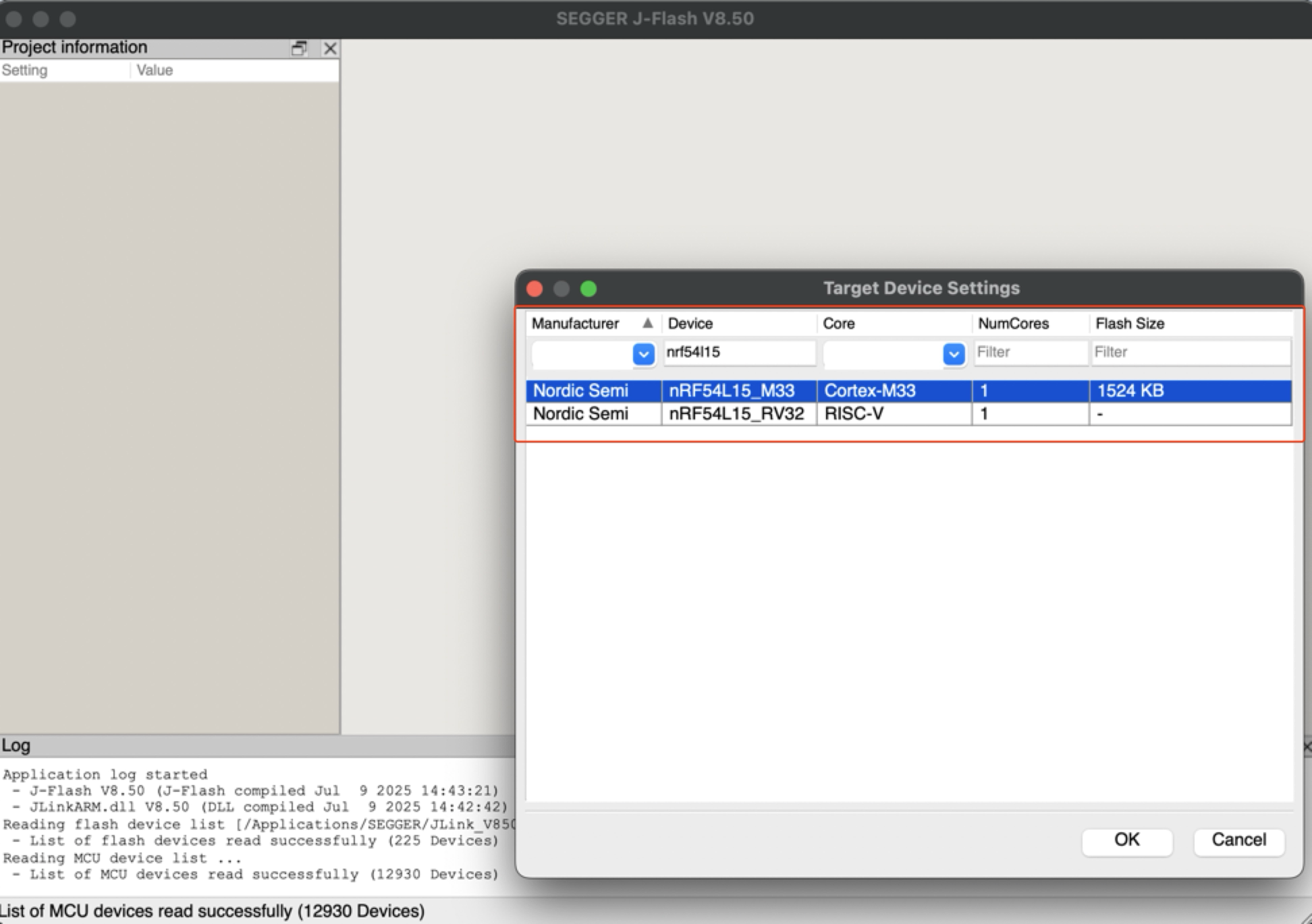
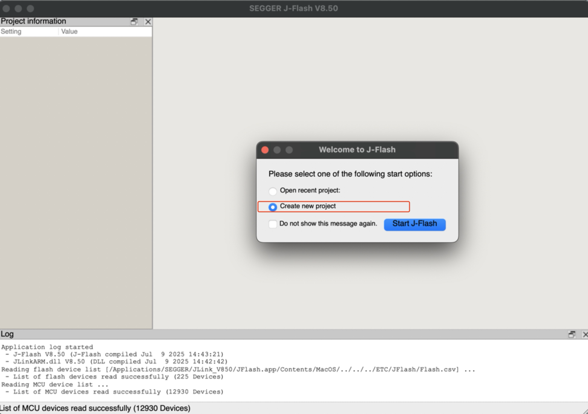
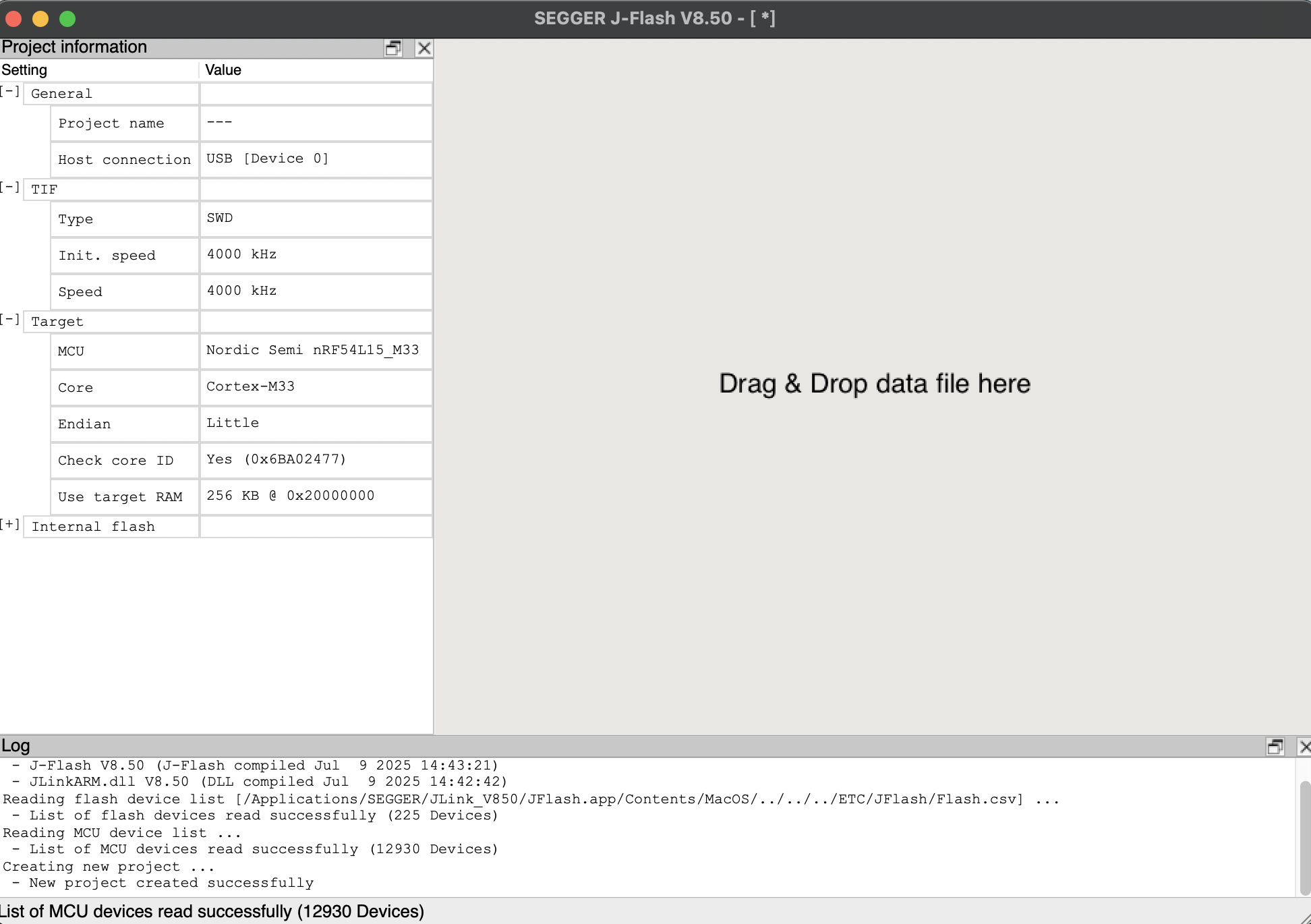
- 步骤 2. 启动 J-Flash 并搜索 nRF54L15_M33,创建一个新工程:
- 步骤 3. 点击 "Target",然后选择 "Connect"。
- 步骤 4. 将 bin 或hex 文件拖入软件中。然后依次按下 F4 和 F5。重新烧录即完成。
电池供电板
XIAO nRF54L15 内置电源管理芯片,使 XIAO nRF54L15 可以通过电池独立供电,或通过 XIAO nRF54L15 的 USB 端口为电池充电。
如果你想为 XIAO 连接电池,我们建议你购买合格的可充电 3.7V 锂电池。焊接电池时,请注意区分正负极。
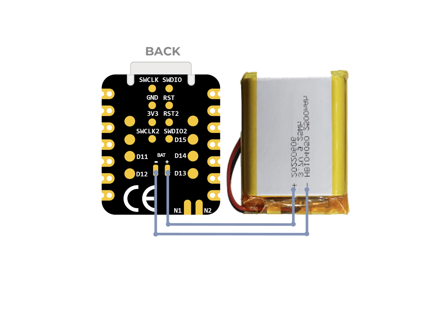
电池连接示意图
电池使用说明:
- 请使用符合规格要求的合格电池。
- 使用电池时,XIAO 也可以通过数据线连接到你的计算机设备,请放心,XIAO 内置电路保护芯片,使用安全。
- 当使用电池供电时,XIAO nRF54L15 不会有任何 LED 亮起(除非你编写了特定程序),请不要通过 LED 的状态来判断 XIAO nRF54L15 是否在工作,而应根据你的程序运行情况进行合理判断。
同时,我们为电池充电设计了一个红色指示灯,通过指示灯的显示来告知用户当前电池的充电状态。
焊接时请注意不要将正负极短路,以免烧毁电池和设备。
电池电压检测
如果你遇到在刷写程序后,仅使用 3.7V 锂电池供电时 XIAO nRF54L15 无法启动的情况,请参考以下解决方案。
对于当前硬件版本(v1.0),我们建议管理两个构建配置,以便在 台式调试(连接 USB,启用 UART)和 电池部署(独立运行,禁用 UART)之间轻松切换。
场景 A:USB 台式调试
适用场景: 你正在编写代码、烧录固件,并需要通过 USB 串口 查看日志。
配置(prj_uart.conf):
在你的项目目录中新建一个名为 prj_uart.conf 的文件。该 overlay 文件将临时重新启用 UART 以用于调试。
# Enable UART for USB debugging
CONFIG_SERIAL=y
CONFIG_UART_CONSOLE=y
# Optional: Keep RTT enabled as a secondary logging backend
CONFIG_USE_SEGGER_RTT=y
CONFIG_RTT_CONSOLE=y
CONFIG_LOG_BACKEND_RTT=y
CONFIG_LOG_BACKEND_UART=y
如何构建: 在构建项目时添加 overlay 配置参数。
# Build with UART enabled for USB debugging
west build -p always -d build_uart -b xiao_nrf54l15/nrf54l15/cpuapp . -DOVERLAY_CONFIG="prj_uart.conf"
场景 B:电池部署(默认)
适用场景: 你已经完成调试,并计划仅通过 电池焊盘 为开发板供电。
配置(prj.conf):
修改主 prj.conf 文件,使 UART 默认禁用。这样可以确保开发板在电池供电时能够正常启动。
# Disable UART to ensure successful boot on battery
CONFIG_SERIAL=n
CONFIG_UART_CONSOLE=n
# Use RTT for low-power logging (requires J-Link)
CONFIG_USE_SEGGER_RTT=y
CONFIG_RTT_CONSOLE=y
CONFIG_LOG=y
CONFIG_LOG_BACKEND_RTT=y
如何构建: 正常构建即可,无需添加 overlay 参数。
# Build default firmware (Battery Safe)
west build -p always -d build_batt -b xiao_nrf54l15/nrf54l15/cpuapp .
小结
- 通过 USB 连接 使用
prj_uart.confoverlay 以启用串口监视器。 - 使用电池运行 使用默认的
prj.conf以确保设备能够正常启动。
XIAO nRF54L15 集成了电池电压检测功能,核心是利用 TPS22916CYFPR 负载开关高效管理电池电源测量。本指南将重点分析电池检测的软件实现 (尤其是 main.c 代码),并指导你如何在 PlatformIO 环境中轻松部署和使用该功能,从而避免直接使用 Zephyr NCS SDK 带来的复杂性。
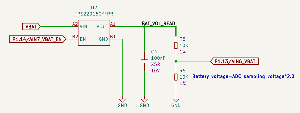
电池检测示意图
TPS22916CYFPR 芯片的作用:
-
它是一颗智能电源开关芯片,可按需控制电池电压的通断。当需要测量电池电压时,它会导通,将电池连接到分压电路;当不需要测量时,它会关断,切断连接。
-
这个特性能帮助我们做什么? 通过这种按需切换机制,该芯片大幅降低了不必要的电流消耗,有效延长电池寿命。结合后级的分压电路以及 nRF54L15 的 ADC(模数转换器),XIAO nRF54L15 能够精确监测电池剩余电量,为物联网设备等电池供电、低功耗应用提供重要的续航优化支持。
下面的示例代码是为 PlatformIO 设计的,但同样兼容 nRF Connect SDK。
在 PlatformIO 中使用 XIAO nRF54L15 如果你想在 PlatformIO 中使用 XIAO nRF54L15,请参考本教程进行配置:XIAO nRF54L15 PlatformIO Configuration。
添加 overlay 并修改 conf 文件
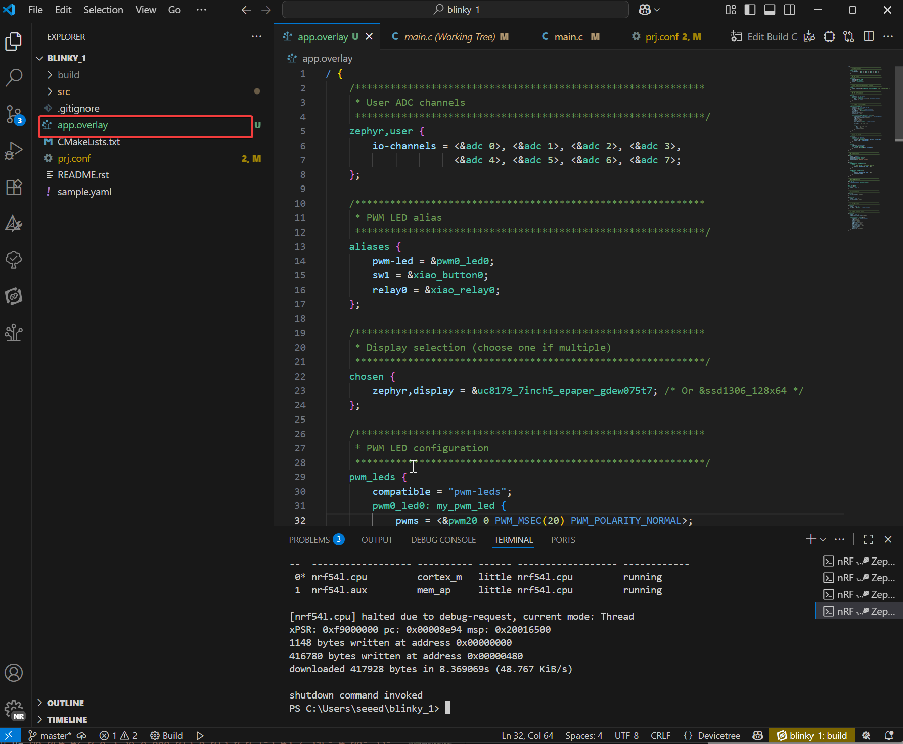
如果你想在 nRF Connect SDK 中使用这个电池示例程序,你需要添加 app.overlay 并修改 prj.conf 文件。
-
在项目目录下新建一个名为
app.overlay的文件。然后将以下代码粘贴进去,最后按 Ctrl + S 保存。- overlay 文件用于扩展硬件描述层,并通过设备树自定义物理硬件连接。它不会修改代码逻辑,而是声明实际的硬件细节,以确保驱动程序能够正确初始化物理设备。
app.overlay 代码
/ {
/*
  * @brief Device Tree Overlay for XIAO nRF54L15
  *
  * This file customizes the base board device tree to configure
  * peripherals for a specific application, including:
  * - User-defined ADC channels
  * - PWM-controlled LED
  * - Buttons and a relay
  * - E-paper display (UC8179) via SPI
  * - OLED display (SSD1306) via I2C
  *
  * To switch between the two displays, simply uncomment one and comment
  * out the other in the "chosen" node below.
  */

/************************************************************
  * Aliases for easy access to devices in application code
  ************************************************************/
aliases {
  pwm-led = &pwm0_led0;
  sw1 = &xiao_button0;
  relay0 = &xiao_relay0;
};

/************************************************************
  * Display selection (choose one if multiple)
  ************************************************************/
chosen {
  zephyr,display = &uc8179_7inch5_epaper_gdew075t7;
  zephyr,display = &ssd1306_128x64;
};

/************************************************************
  * PWM LED, Button, and Relay configuration
  ************************************************************/
pwm_leds {
  compatible = "pwm-leds";
  pwm0_led0: my_pwm_led {
    // PWM channel 0 on PWM instance 20
    // PWM_MSEC(20) sets a period of 20ms
    pwms = <&pwm20 0 PWM_MSEC(20) PWM_POLARITY_NORMAL>;
    status = "okay";
  };
};

buttons {
  compatible = "gpio-keys";
  xiao_button0: button_0 {
    // Connect to the XIAO nRF54L15 pin D1
    // GPIO_PULL_UP ensures the pin is high when the button is not pressed
    // GPIO_ACTIVE_LOW means the button press drives the pin low
    gpios = <&xiao_d 1 (GPIO_PULL_UP | GPIO_ACTIVE_LOW)>;
    zephyr,code = <INPUT_KEY_0>;
  };
};

relay {
  compatible = "gpio-leds";
  xiao_relay0: relay_0 {
    // Connect to the XIAO nRF54L15 pin D0
    gpios = <&xiao_d 0 GPIO_ACTIVE_HIGH>;
  };
};

/************************************************************
  * Local nodes that don't modify existing ones
  ************************************************************/
zephyr,user {
  io-channels = <&adc 0>, <&adc 1>, <&adc 2>, <&adc 3>,
          <&adc 4>, <&adc 5>, <&adc 6>, <&adc 7>;
};

// MIPI-DBI SPI interface for the E-paper display
mipi_dbi_xiao_epaper {
  compatible = "zephyr,mipi-dbi-spi";
  spi-dev = <&xiao_spi>;
  // D3 pin for Data/Command control
  dc-gpios = <&xiao_d 3 GPIO_ACTIVE_HIGH>;
  // D0 pin for Reset
  reset-gpios = <&xiao_d 0 GPIO_ACTIVE_LOW>;
  write-only;
  #address-cells = <1>;
  #size-cells = <0>;

  uc8179_7inch5_epaper_gdew075t7: uc8179@0 {
    compatible = "gooddisplay,gdew075t7", "ultrachip,uc8179";
    // Max SPI frequency for the display
    mipi-max-frequency = <4000000>;
    reg = <0>;
    width = <800>;
    height = <480>;
    // D2 pin for Busy signal from the display
    busy-gpios = <&xiao_d 2 GPIO_ACTIVE_LOW>;
    softstart = [17 17 17 17];
    full {
      pwr = [07 07 3f 3f];
      cdi = <07>;
      tcon = <0x22>;
    };
  };
};
};

/************************************************************
* Device fragments (modifying nodes from the base board DTS)
************************************************************/
// PWM instance 20
&pwm20 {
status = "okay";
pinctrl-0 = <&pwm20_default>;
pinctrl-1 = <&pwm20_sleep>;
pinctrl-names = "default", "sleep";
};

// GPIO pin control
&pinctrl {
pwm20_default: pwm20_default {
  group1 {
    // Configure PWM channel 0 on P1.04 pin (Pin D0)
    psels = <NRF_PSEL(PWM_OUT0, 1, 4)>;
  };
};

pwm20_sleep: pwm20_sleep {
  group1 {
    psels = <NRF_PSEL(PWM_OUT0, 1, 4)>;
    low-power-enable;
  };
};
};

// PDM instance 20 for DMIC
dmic_dev: &pdm20 {
status = "okay";
};

// Power configuration
&pdm_imu_pwr {
/delete-property/ regulator-boot-on;
};

// UART instance 20
&uart20 {
current-speed = <921600>;
};

// SPI peripheral
&xiao_spi {
status = "okay";
// D1 pin for Chip Select
cs-gpios = <&xiao_d 1 GPIO_ACTIVE_LOW>;
};

// I2C peripheral
&xiao_i2c {
status = "okay";
zephyr,concat-buf-size = <2048>;

ssd1306_128x64: ssd1306@3c {
  compatible = "solomon,ssd1306fb";
  reg = <0x3c>;
  width = <128>;
  height = <64>;
  segment-offset = <0>;
  page-offset = <0>;
  display-offset = <0>;
  multiplex-ratio = <63>;
  segment-remap;
  com-invdir;
  prechargep = <0x22>;
};
};
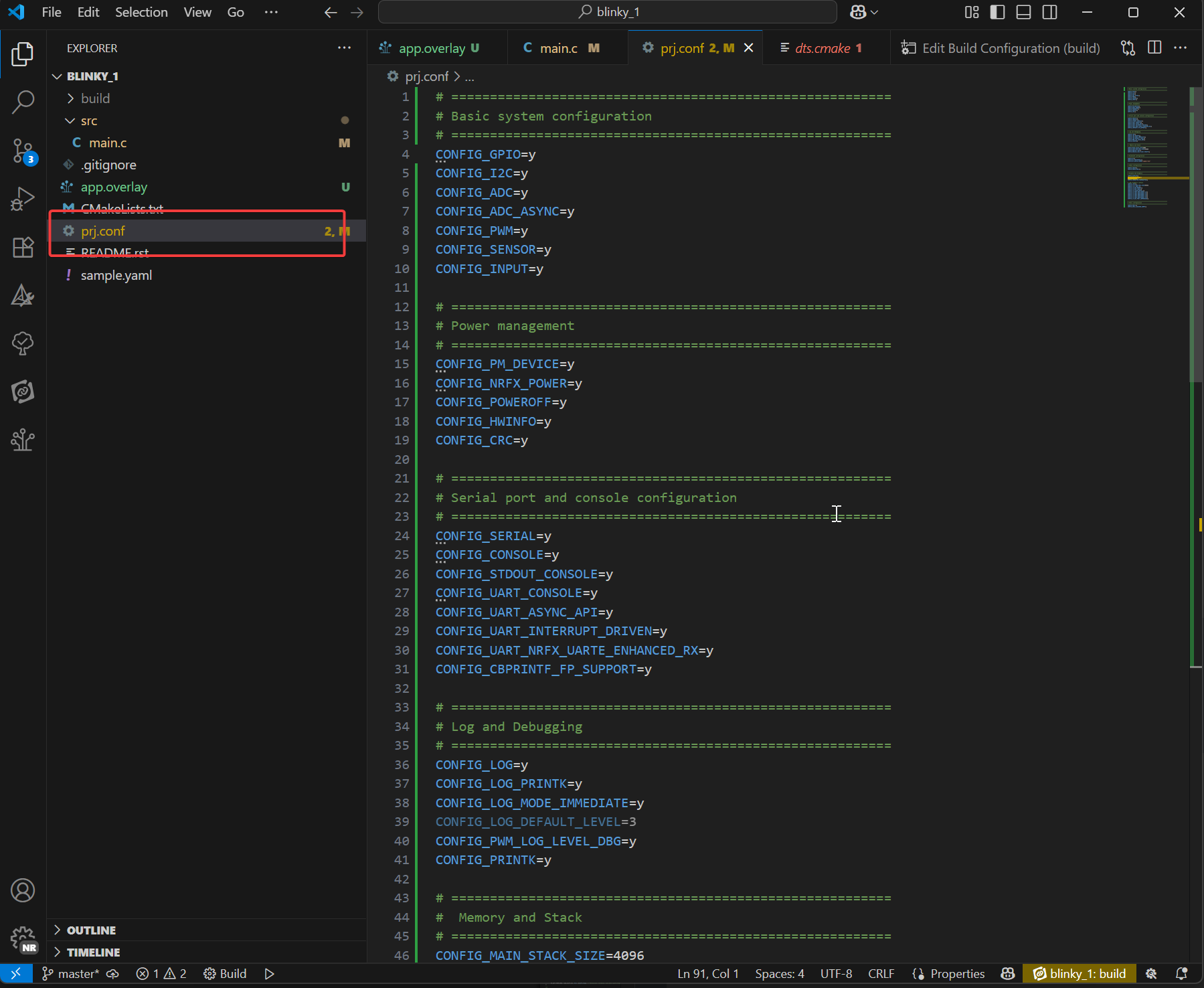
-
在 prj.conf 文件下添加以下内容
- prj.conf 是 Zephyr 项目的核心配置文件。它由 Kconfig 系统管理,用于在编译期间选择软件功能。它决定固件中包含哪些驱动程序(例如 ADC、显示、蓝牙)、中间件(例如 LVGL)和系统服务(例如日志、内存管理),并设置它们的行为参数(例如日志级别、堆大小),最后按 Ctrl + S 保存。
prj.conf 代码
# =========================================================
# Basic system configuration
# =========================================================
CONFIG_GPIO=y
CONFIG_I2C=y
CONFIG_ADC=y
CONFIG_ADC_ASYNC=y
CONFIG_PWM=y
CONFIG_SENSOR=y
CONFIG_INPUT=y

# =========================================================
# Power management
# =========================================================
CONFIG_PM_DEVICE=y
CONFIG_NRFX_POWER=y
CONFIG_POWEROFF=y
CONFIG_HWINFO=y
CONFIG_CRC=y

# =========================================================
# Serial port and console configuration
# =========================================================
CONFIG_SERIAL=y
CONFIG_CONSOLE=y
CONFIG_STDOUT_CONSOLE=y
CONFIG_UART_CONSOLE=y
CONFIG_UART_ASYNC_API=y
CONFIG_UART_INTERRUPT_DRIVEN=y
CONFIG_UART_NRFX_UARTE_ENHANCED_RX=y
CONFIG_CBPRINTF_FP_SUPPORT=y

# =========================================================
# Log and Debugging
# =========================================================
CONFIG_LOG=y
CONFIG_LOG_PRINTK=y
CONFIG_LOG_MODE_IMMEDIATE=y
CONFIG_LOG_DEFAULT_LEVEL=3
CONFIG_PWM_LOG_LEVEL_DBG=y
CONFIG_PRINTK=y

# =========================================================
#  Memory and Stack
# =========================================================
CONFIG_MAIN_STACK_SIZE=4096
CONFIG_HEAP_MEM_POOL_SIZE=16384
CONFIG_NEWLIB_LIBC=y
CONFIG_NEWLIB_LIBC_FLOAT_PRINTF=y

# =========================================================
# Bluetooth configuration
# =========================================================
CONFIG_BT=y
CONFIG_BT_PERIPHERAL=y
CONFIG_BT_DEVICE_NAME="zephyr-ble"

# =========================================================
# Audio configuration
# =========================================================
CONFIG_AUDIO=y
CONFIG_AUDIO_DMIC=y

# =========================================================
# Display and Graphics
# =========================================================
CONFIG_DISPLAY=y
CONFIG_MIPI_DBI_SPI=y
CONFIG_SSD1306=y
CONFIG_CHARACTER_FRAMEBUFFER=y

# LVGL Graphics Library
CONFIG_LVGL=y
CONFIG_LV_Z_MEM_POOL_SIZE=49152
CONFIG_LV_Z_SHELL=y
CONFIG_LV_USE_MONKEY=y
CONFIG_LV_USE_LABEL=y
CONFIG_LV_COLOR_DEPTH_1=y
CONFIG_LV_FONT_MONTSERRAT_12=y
CONFIG_LV_FONT_MONTSERRAT_14=y
CONFIG_LV_FONT_MONTSERRAT_16=y
CONFIG_LV_FONT_MONTSERRAT_18=y
CONFIG_LV_FONT_MONTSERRAT_24=y
CONFIG_LV_USE_FONT_COMPRESSED=y

# =========================================================
# Shell configuration
# =========================================================
CONFIG_SHELL=y
CONFIG_SHELL_BACKEND_DUMMY=y
核心代码
#include <inttypes.h>
#include <stddef.h>
#include <stdint.h>
#include <zephyr/device.h>
#include <zephyr/devicetree.h>
#include <zephyr/drivers/regulator.h>
#include <zephyr/drivers/adc.h>
#include <zephyr/kernel.h>


#if !DT_NODE_EXISTS(DT_PATH(zephyr_user)) || \
 !DT_NODE_HAS_PROP(DT_PATH(zephyr_user), io_channels)
#error "No suitable devicetree overlay specified"
#endif

#define DT_SPEC_AND_COMMA(node_id, prop, idx) \
 ADC_DT_SPEC_GET_BY_IDX(node_id, idx),

/* Data of ADC io-channels specified in devicetree. */
static const struct adc_dt_spec adc_channels[] = {
 DT_FOREACH_PROP_ELEM(DT_PATH(zephyr_user), io_channels,
       DT_SPEC_AND_COMMA)};

static const struct device *const vbat_reg = DEVICE_DT_GET(DT_NODELABEL(vbat_pwr));

int main(void)
{
 int err;
 uint16_t buf;
 int32_t val_mv;
 struct adc_sequence sequence = {
  .buffer = &buf,
  /* buffer size in bytes, not number of samples */
  .buffer_size = sizeof(buf),
 };

 regulator_enable(vbat_reg);
 k_sleep(K_MSEC(100));

 /* Configure channels individually prior to sampling. */
 if (!adc_is_ready_dt(&adc_channels[7]))
 {
  printf("ADC controller device %s not ready\n", adc_channels[7].dev->name);
  return 0;
 }

 err = adc_channel_setup_dt(&adc_channels[7]);
 if (err < 0)
 {
  printf("Could not setup channel #7 (%d)\n", err);
  return 0;
 }

 (void)adc_sequence_init_dt(&adc_channels[7], &sequence);

 err = adc_read_dt(&adc_channels[7], &sequence);
 if (err < 0)
 {
  printf("Could not read (%d)\n", err);
  return 0;
 }

 /*
  * If using differential mode, the 16 bit value
  * in the ADC sample buffer should be a signed 2's
  * complement value.
  */
 if (adc_channels[7].channel_cfg.differential)
 {
  val_mv = (int32_t)((int16_t)buf);
 }
 else
 {
  val_mv = (int32_t)buf;
 }
 err = adc_raw_to_millivolts_dt(&adc_channels[7],
           &val_mv);
 /* conversion to mV may not be supported, skip if not */
 if (err < 0)
 {
  printf(" value in mV not available\n");
 }
 else
 {
  printf("bat vol = %" PRId32 " mV\n", val_mv * 2);
 }

 regulator_disable(vbat_reg);
 return 0;
}
资源
Seeed Studio XIAO nRF54L15
硬件设计
- 📄[数据手册] Nordic nRF54L15 Datasheet
- 📄[原理图] XIAO nRF54L15 Schematic
- 🗃️[PCB 设计文件] XIAO nRF54L15 KiCad Project
- 🗃️[PCB 设计库]
- 📄[引脚图] XIAO nRF54L15 Pinout Sheet
机械结构
- 🗃️[2D 尺寸] XIAO nRF54L15 Dimension in DXF
Seeed Studio XIAO nRF54L15 Sense
硬件设计
- 📄[数据手册] Nordic nRF54L15 Datasheet
- 📄[原理图] XIAO nRF54L15 Sense Schematic
- 🗃️[PCB 设计文件]
- 🗃️[PCB 设计库]
- 🗃️[引脚图] XIAO nRF54L15 Sense Pinout Sheet
机械结构
- 📄[2D 尺寸] XIAO nRF54L15 Sense Dimension in DXF
- 🗃️[3D 尺寸] XIAO nRF54L15 Sense 3D imensions
技术支持与产品讨论
感谢您选择我们的产品!我们将为您提供多种支持,以确保您在使用我们产品的过程中尽可能顺畅。我们提供多种沟通渠道,以满足不同的偏好和需求。