XIAO nRF54LM20A Sense 的低功耗模式
XIAO nRF54LM20A 基于 nRF54LM20 SoC 构建,具备超低功耗特性。其出色的低功耗性能可有效延长对电池续航要求严苛的应用(如可穿戴设备、物联网终端节点和远程传感单元)的运行时间。本文档介绍如何在 XIAO nRF54LM20A 上实现并部署多种低功耗模式。
本教程基于 PlatformIO 构建系统和 Zephyr RTOS 开发。如果你还不熟悉如何在 PlatformIO 下为 XIAO nRF54LM20A 创建项目,可以跳转到 Getting Sarted With Seeed Studio XIAO nRF54LM20A。
硬件准备
| SeeedStudio XIAO nRF54LM20A Sense |
|---|
使用电池供电
本章实现的所有模式均通过 XIAO nRF54LM20A 底部焊盘使用电池供电,而非通过 USB-C 供电。 XIAO nRF54LM20A 支持使用 3.7V 锂电池作为电源输入。你可以参考下图进行接线。
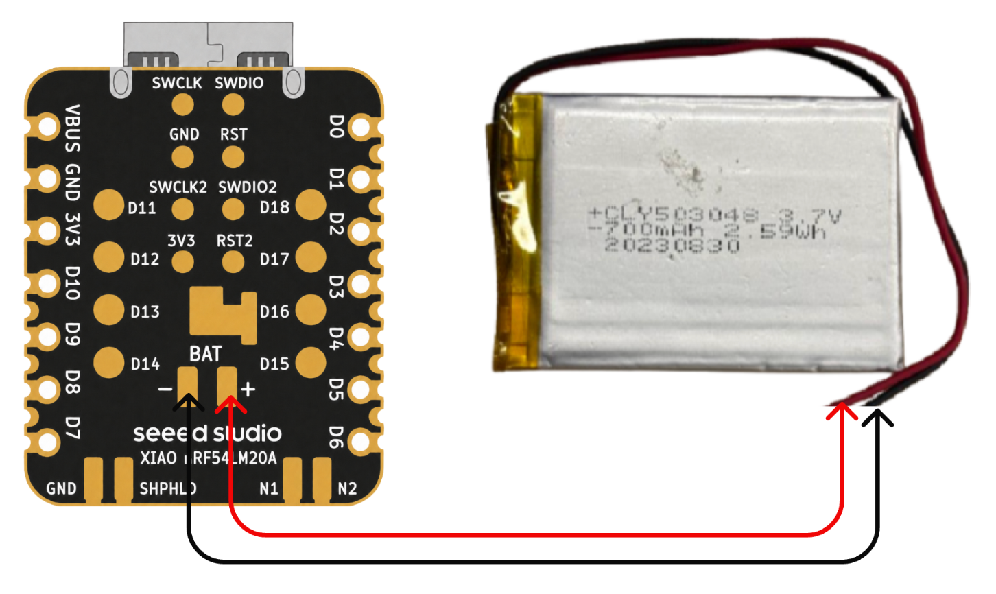
焊接时请务必注意不要将正负极短路,以免烧毁电池和设备。 如果电池本身带电,切勿直接焊接到电路板上,否则可能烧毁电路板。在电路上电的情况下发生短路风险极大,建议使用转接座或适配器。
低功耗模式
在 XIAO nRF54LM20A 上通过 System ON Sleep 等功能实现低功耗模式。在该模式下,系统仍保持工作,但功耗显著降低。CPU 时钟被门控并暂停运行,但 RAM 内容、外设状态和程序上下文均被完整保留,且包括 GRTC 在内的低功耗定时器仍在运行。本节通过 k_sleep 函数和 BLE 广播来验证低功耗模式。
软件
- 修改以
.overlay结尾的设备树文件。
/ {
    chosen {
        zephyr,bt-hci = &bt_hci_controller;
    };
};

&bt_hci_controller {
    status = "okay";
};

/* Disable unused regulators to reduce standby power */
&power_en {
    /delete-property/ regulator-boot-on;
};

&pmic {
    regulators {
        LDO1 {
            /delete-property/ regulator-boot-on;
        };
    };
};
- 修改
prj.conf配置文件以启用系统电源管理相关设置。
CONFIG_GPIO=y
CONFIG_ARM_MPU=n
CONFIG_NRFX_POWER=y
CONFIG_POWEROFF=y
CONFIG_HWINFO=y
CONFIG_CRC=y

# Device power management (peripheral level)
CONFIG_PM_DEVICE=y
CONFIG_PM_DEVICE_RUNTIME=y

# Bluetooth
CONFIG_BT=y
CONFIG_BT_BROADCASTER=y
CONFIG_BT_DEVICE_NAME="XIAO nRF54LM20A"
CONFIG_BT_CTLR_ASSERT_OPTIMIZE_FOR_SIZE=n
CONFIG_BT_CTLR_ASSERT_DEBUG=n
CONFIG_BT_CTLR_ASSERT_OVERHEAD_START=n
- 修改 main.c 程序,通过
k_sleep(K_SECONDS(10))启用低功耗模式,并配置 BLE 以 1 秒间隔周期性广播消息。
/*
* BLE Low Power Broadcasting Demo for XIAO nRF54LM20A
*/
#include <zephyr/kernel.h>
#include <zephyr/bluetooth/bluetooth.h>
#include <zephyr/bluetooth/hci.h>
/* 1000ms / 0.625ms = 1600 = 0x0640 */
#define ADV_INTERVAL_1S 0x0640
static const struct bt_data ad[] = {
BT_DATA_BYTES(BT_DATA_FLAGS, (BT_LE_AD_GENERAL | BT_LE_AD_NO_BREDR)),
BT_DATA(BT_DATA_NAME_COMPLETE, "XIAO nRF54LM20A", 15),
};
static void bt_ready(int err)
{
if (err) {
return;
}
struct bt_le_adv_param param = BT_LE_ADV_PARAM_INIT(
BT_LE_ADV_OPT_NONE,
ADV_INTERVAL_1S,
ADV_INTERVAL_1S,
NULL
);
bt_le_adv_start(¶m, ad, ARRAY_SIZE(ad), NULL, 0);
}
int main(void)
{
bt_enable(bt_ready);
/* BLE controller handles advertising autonomously; CPU sleeps */
while (1) {
k_sleep(K_SECONDS(10));
}
return 0;
}
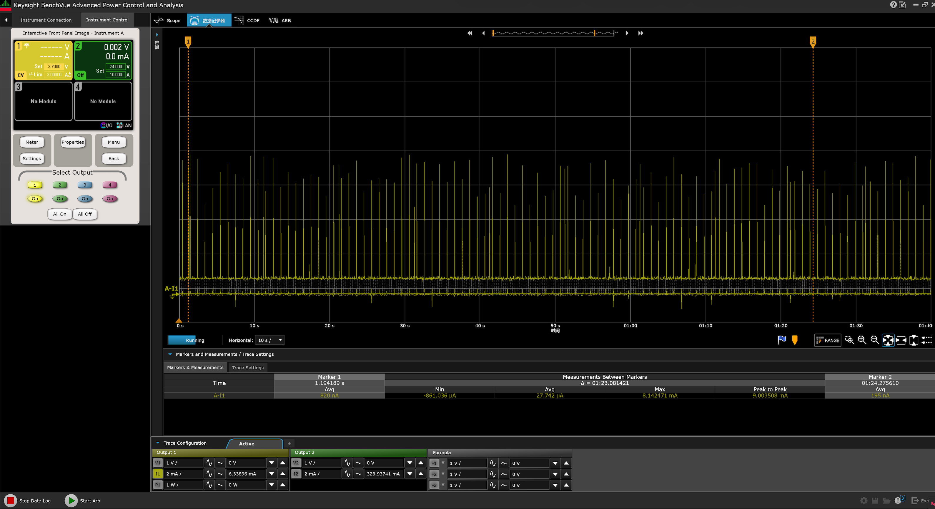
测试结果
烧录固件后,我们可以使用功耗测试仪测量 XIAO nRF54LM20A 在低功耗条件下的工作电流。
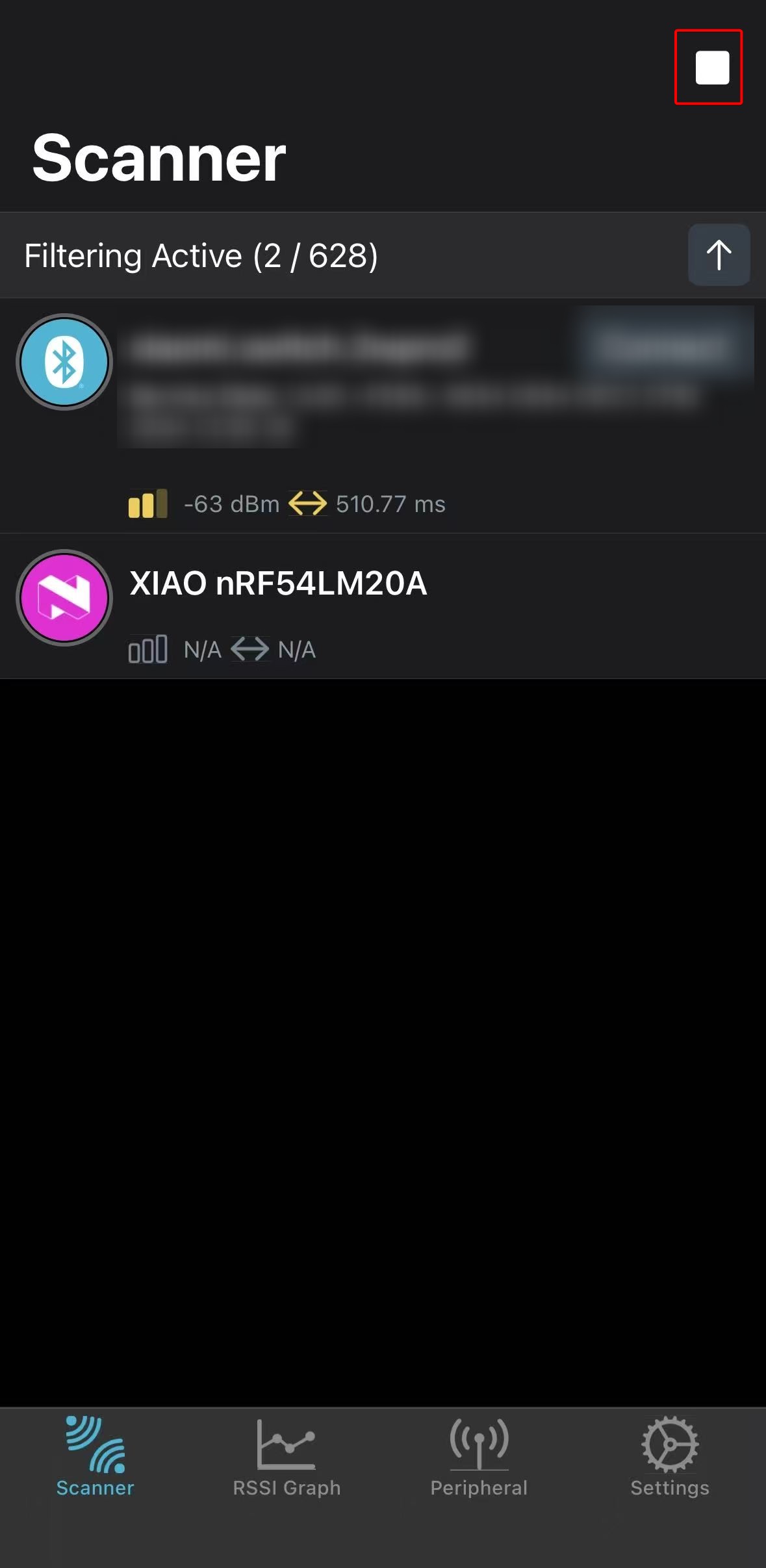
同时,你可以通过蓝牙扫描,并找到以 XIAO nRF54LM20A 为名称进行广播的设备。
- Android: nRF Connect
- IOS: nRF Connect
 | 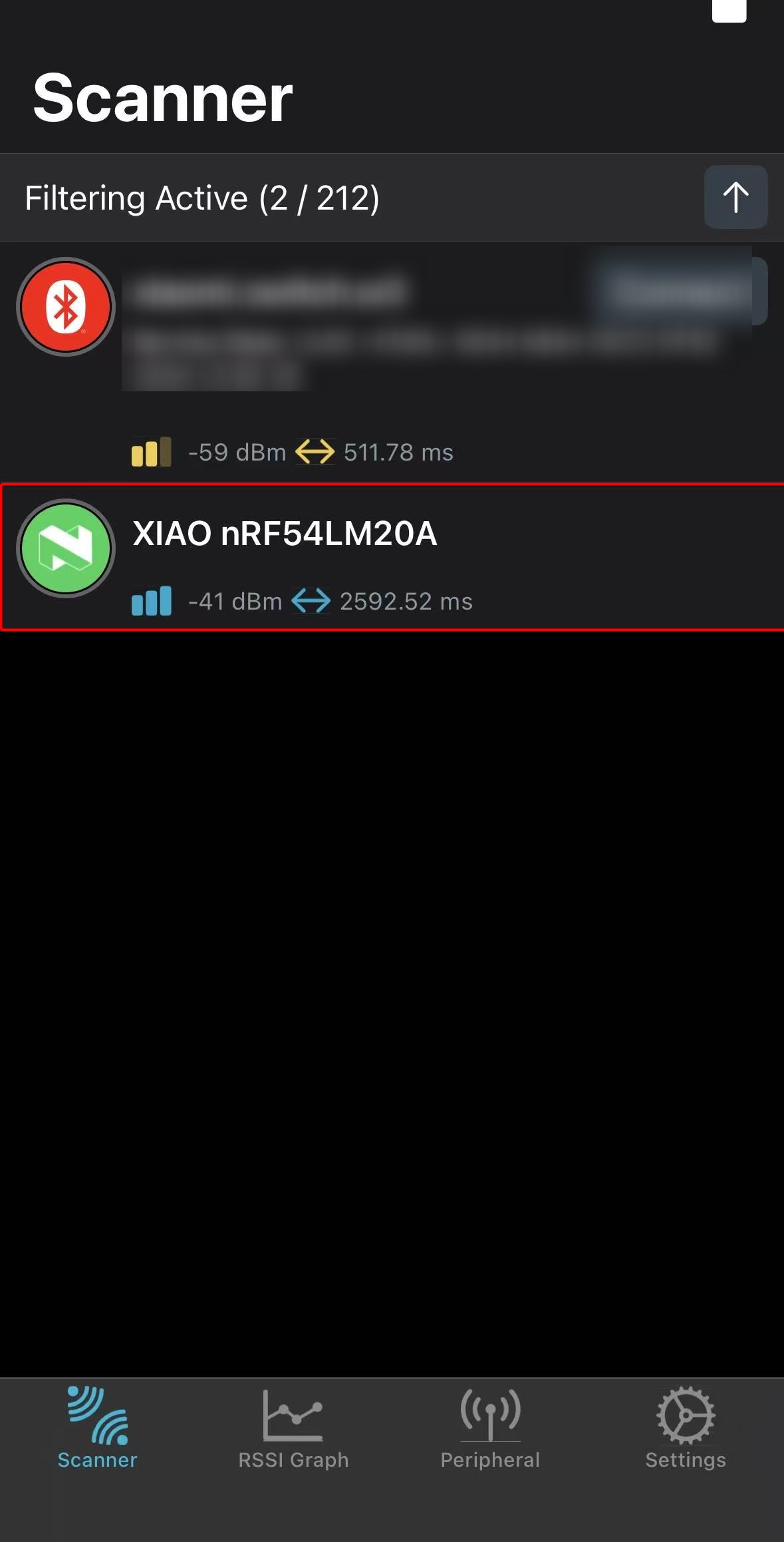 |
以上测试结果均在实验室条件下测得。不同环境和测试仪器可能导致数值有所差异,请以实际测量性能为准。
超低功耗模式
XIAO nRF54LM20A 通过 System OFF 实现超低功耗模式。进入该模式后,所有外设时钟停止,大部分外设完全断电,待机电流最低可达 5 µA。唤醒源包括 GRTC 定时器或 GPIO 中断。系统状态不会被保留;唤醒后芯片行为等同于重新上电,程序从 main() 函数重新开始执行。
本节通过 GPIO 中断唤醒的方式,验证 XIAO nRF54LM20A 在 System OFF 模式下的实际性能。
软件
在本示例中,需要手动将外部 Flash 置于深度掉电模式,并将其 SPI 引脚驱动到确定的电平状态,否则可能引入额外的漏电流。
- 修改以
.overlay为后缀的设备树文件。
&power_en {
	/delete-property/ regulator-boot-on;
};

&pmic {
	regulators {
		LDO1 {
			/delete-property/ regulator-boot-on;
		};
	};
};

&pmic_leds {
	status = "disabled";
};

&py25q64 {
	status = "okay";
};
- 修改
prj.conf文件以启用包括电源管理在内的相关配置。
CONFIG_SERIAL=y
CONFIG_CONSOLE=y
CONFIG_UART_CONSOLE=y
CONFIG_PRINTK=y
CONFIG_BOOT_BANNER=n

CONFIG_GPIO=y
CONFIG_SPI=y
CONFIG_FLASH=y
CONFIG_SPI_NOR=y

CONFIG_PM_DEVICE=y
CONFIG_PM_DEVICE_RUNTIME=y
CONFIG_POWEROFF=y
CONFIG_HWINFO=y

CONFIG_BT=n
- 编写 main.c 程序,使按下板载 Boot 按钮时可以将芯片从超低功耗模式唤醒。
main.c
/*
 * Copyright (c) 2019 Nordic Semiconductor ASA
 *
 * SPDX-License-Identifier: Apache-2.0
 */
/*
 * Ultra-low-power System OFF demo for XIAO nRF54LM20A Sense.
 *
 * Confirmed board resources from the board DTS:
 * - sw0 / BOOT: P0.09 (active low with pull-up)
 * - External flash (PY25Q64HA) on spi00:
 *   HOLD# P2.00, SCK P2.01, MOSI P2.02, WP# P2.03, MISO P2.04, CS# P2.05
 * - RGB LEDs on P1.22 / P1.23 / P1.24
 */
#include <errno.h>
#include <inttypes.h>
#include <stdio.h>

#include <zephyr/device.h>
#include <zephyr/drivers/gpio.h>
#include <zephyr/drivers/hwinfo.h>
#include <zephyr/kernel.h>
#include <zephyr/pm/device.h>
#include <zephyr/sys/poweroff.h>

static const struct gpio_dt_spec sw0 = GPIO_DT_SPEC_GET(DT_ALIAS(sw0), gpios);
static const struct gpio_dt_spec led_red = GPIO_DT_SPEC_GET(DT_ALIAS(led1), gpios);
static const struct gpio_dt_spec led_blue = GPIO_DT_SPEC_GET(DT_ALIAS(led0), gpios);
static const struct gpio_dt_spec led_green = GPIO_DT_SPEC_GET(DT_ALIAS(led2), gpios);

#if DT_NODE_EXISTS(DT_CHOSEN(zephyr_console))
static const struct device *const cons = DEVICE_DT_GET(DT_CHOSEN(zephyr_console));
#endif

#if DT_NODE_HAS_STATUS(DT_NODELABEL(py25q64), okay)
static const struct device *const flash_dev = DEVICE_DT_GET(DT_NODELABEL(py25q64));
static const struct device *const flash_bus = DEVICE_DT_GET(DT_BUS(DT_NODELABEL(py25q64)));
#endif

static void print_reset_cause(uint32_t reset_cause)
{
	if (reset_cause & RESET_DEBUG) {
		printf("Reset by debugger.\n");
	} else if (reset_cause & RESET_CLOCK) {
		printf("Wakeup from System OFF by clock source.\n");
	} else if (reset_cause & RESET_LOW_POWER_WAKE) {
		printf("Wakeup from System OFF by GPIO.\n");
	} else if (reset_cause != 0U) {
		printf("Other wake up cause 0x%08" PRIX32 ".\n", reset_cause);
	} else {
		printf("Power-on reset or reset cause unavailable.\n");
	}
}

static int configure_gpio_wakeup(void)
{
	int rc;

	if (!gpio_is_ready_dt(&sw0)) {
		printf("sw0 GPIO device not ready.\n");
		return -ENODEV;
	}

	rc = gpio_pin_configure_dt(&sw0, GPIO_INPUT);
	if (rc < 0) {
		printf("Could not configure sw0 GPIO (%d)\n", rc);
		return rc;
	}

	rc = gpio_pin_interrupt_configure_dt(&sw0, GPIO_INT_LEVEL_ACTIVE);
	if (rc < 0) {
		printf("Could not configure sw0 GPIO interrupt (%d)\n", rc);
		return rc;
	}

	return 0;
}

static void release_led(const struct gpio_dt_spec *led, const char *name)
{
	int rc;

	if (!gpio_is_ready_dt(led)) {
		return;
	}

	rc = gpio_pin_configure(led->port, led->pin, GPIO_DISCONNECTED);
	if (rc < 0) {
		printf("Warning: could not disconnect %s (%d)\n", name, rc);
	}
}

static void release_led_gpios(void)
{
	release_led(&led_red, "red LED");
	release_led(&led_blue, "blue LED");
	release_led(&led_green, "green LED");
}

/*
 * Put the external flash pins into deterministic, low-leakage states before
 * System OFF. These pin numbers are confirmed by the board pinctrl and DTS.
 */
static int configure_spi_pins_for_system_off(void)
{
	const struct device *gpio2 = DEVICE_DT_GET(DT_NODELABEL(gpio2));
	int rc;

	if (!device_is_ready(gpio2)) {
		printf("GPIO2 not ready.\n");
		return -ENODEV;
	}

	rc = gpio_pin_configure(gpio2, 5, GPIO_OUTPUT_HIGH);
	if (rc < 0) {
		return rc;
	}

	rc = gpio_pin_configure(gpio2, 0, GPIO_OUTPUT_HIGH);
	if (rc < 0) {
		return rc;
	}

	rc = gpio_pin_configure(gpio2, 3, GPIO_OUTPUT_HIGH);
	if (rc < 0) {
		return rc;
	}

	rc = gpio_pin_configure(gpio2, 1, GPIO_OUTPUT_LOW);
	if (rc < 0) {
		return rc;
	}

	rc = gpio_pin_configure(gpio2, 2, GPIO_OUTPUT_LOW);
	if (rc < 0) {
		return rc;
	}

	rc = gpio_pin_configure(gpio2, 4, GPIO_INPUT | GPIO_PULL_DOWN);
	if (rc < 0) {
		return rc;
	}

	return 0;
}

static int suspend_external_flash(void)
{
	int first_error = 0;
	int rc;

#if DT_NODE_HAS_STATUS(DT_NODELABEL(py25q64), okay)
	if (device_is_ready(flash_dev)) {
		rc = pm_device_action_run(flash_dev, PM_DEVICE_ACTION_SUSPEND);
		if ((rc < 0) && (first_error == 0)) {
			first_error = rc;
			printf("Warning: could not suspend external flash (%d)\n", rc);
		}
	} else {
		first_error = -ENODEV;
		printf("Warning: flash device is not ready; skipping driver DPD.\n");
	}

	if (device_is_ready(flash_bus)) {
		rc = pm_device_action_run(flash_bus, PM_DEVICE_ACTION_SUSPEND);
		if ((rc < 0) && (first_error == 0)) {
			first_error = rc;
			printf("Warning: could not suspend SPI bus (%d)\n", rc);
		}
	} else if (first_error == 0) {
		first_error = -ENODEV;
		printf("Warning: flash SPI bus is not ready.\n");
	}
#else
	first_error = -ENODEV;
	printf("Warning: py25q64 is not enabled in DTS.\n");
#endif

	rc = configure_spi_pins_for_system_off();
	if ((rc < 0) && (first_error == 0)) {
		first_error = rc;
		printf("Warning: could not configure flash SPI pins (%d)\n", rc);
	}

	return first_error;
}

static void suspend_console_best_effort(void)
{
#if DT_NODE_EXISTS(DT_CHOSEN(zephyr_console))
	int rc;

	if (!device_is_ready(cons)) {
		return;
	}

	rc = pm_device_action_run(cons, PM_DEVICE_ACTION_SUSPEND);
	if (rc < 0) {
		printf("Warning: could not suspend console (%d)\n", rc);
	}
#endif
}

int main(void)
{
	int rc;
	uint32_t reset_cause = 0U;

	printf("\n=== %s ultra-low-power system off demo ===\n", CONFIG_BOARD);

	rc = hwinfo_get_reset_cause(&reset_cause);
	if (rc == 0) {
		print_reset_cause(reset_cause);
	} else {
		printf("Warning: could not read reset cause (%d)\n", rc);
	}

	rc = configure_gpio_wakeup();
	if (rc < 0) {
		printf("Error: wakeup source configuration failed, aborting System OFF.\n");
		return 0;
	}

	release_led_gpios();

	rc = suspend_external_flash();
	if (rc < 0) {
		printf("Warning: flash low-power preparation incomplete (%d)\n", rc);
	}

	printf("Entering system off; press BOOT/SW0 to restart.\n");
	k_msleep(20);

	suspend_console_best_effort();

	rc = hwinfo_clear_reset_cause();
	if (rc < 0) {
		/* Clear failure should not stop entry into System OFF. */
		printf("Warning: could not clear reset cause (%d)\n", rc);
	}

	sys_poweroff();

	while (1) {
		k_sleep(K_FOREVER);
	}
}
测试结果
启动后,固件会准备唤醒源和外部外设,然后自动进入 System OFF。使用功耗测试仪对 XIAO nRF54LM20A 进行测量,当由 3.7 V 电池供电时,其平均工作电流约为 3.74 µA。
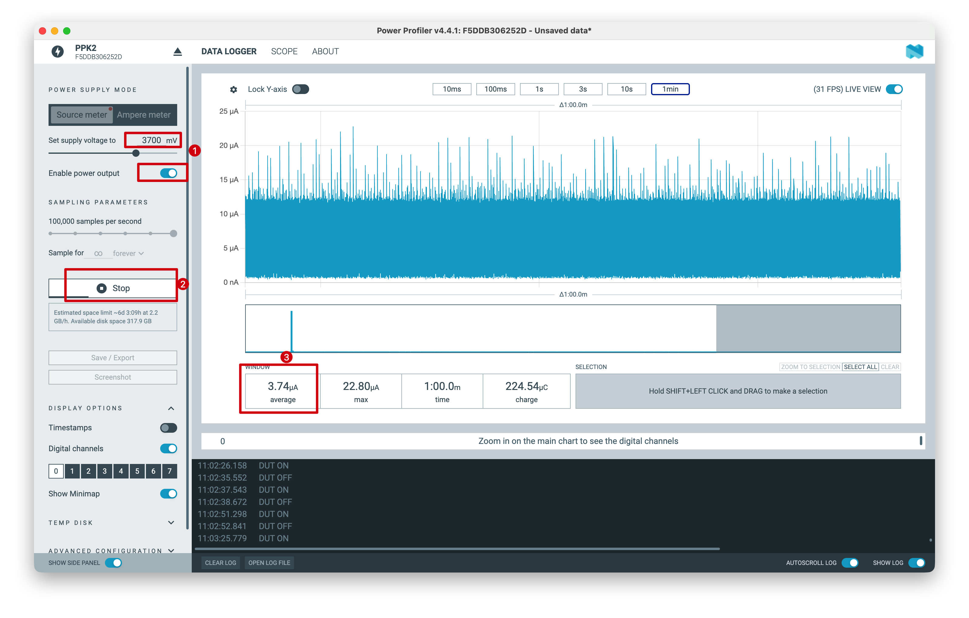
以上测试结果是在实验室条件下测得的。数值可能会因环境和测试仪器不同而有所差异,请以实际测量性能为准。
技术支持与产品讨论
感谢您选择我们的产品!我们将为您提供多种支持,确保您在使用我们产品的过程中尽可能顺畅。我们提供多种沟通渠道,以满足不同的偏好和需求。