使用 Seeed Studio XIAO ESP32C6 进行 Arduino 编程
| Seeed Studio XIAO ESP32C6 |
|---|
 |
Seeed Studio XIAO ESP32C6 由高度集成的 ESP32-C6 SoC 提供动力,基于两个 32 位 RISC-V 处理器构建,其中高性能 (HP) 处理器最高运行频率可达 160 MHz,低功耗 (LP) 32 位 RISC-V 处理器最高可达 20 MHz。芯片上集成有 512KB SRAM 和 4 MB Flash,为编程提供了更大的空间,为物联网控制场景带来更多可能性。
入门指南
引脚总览
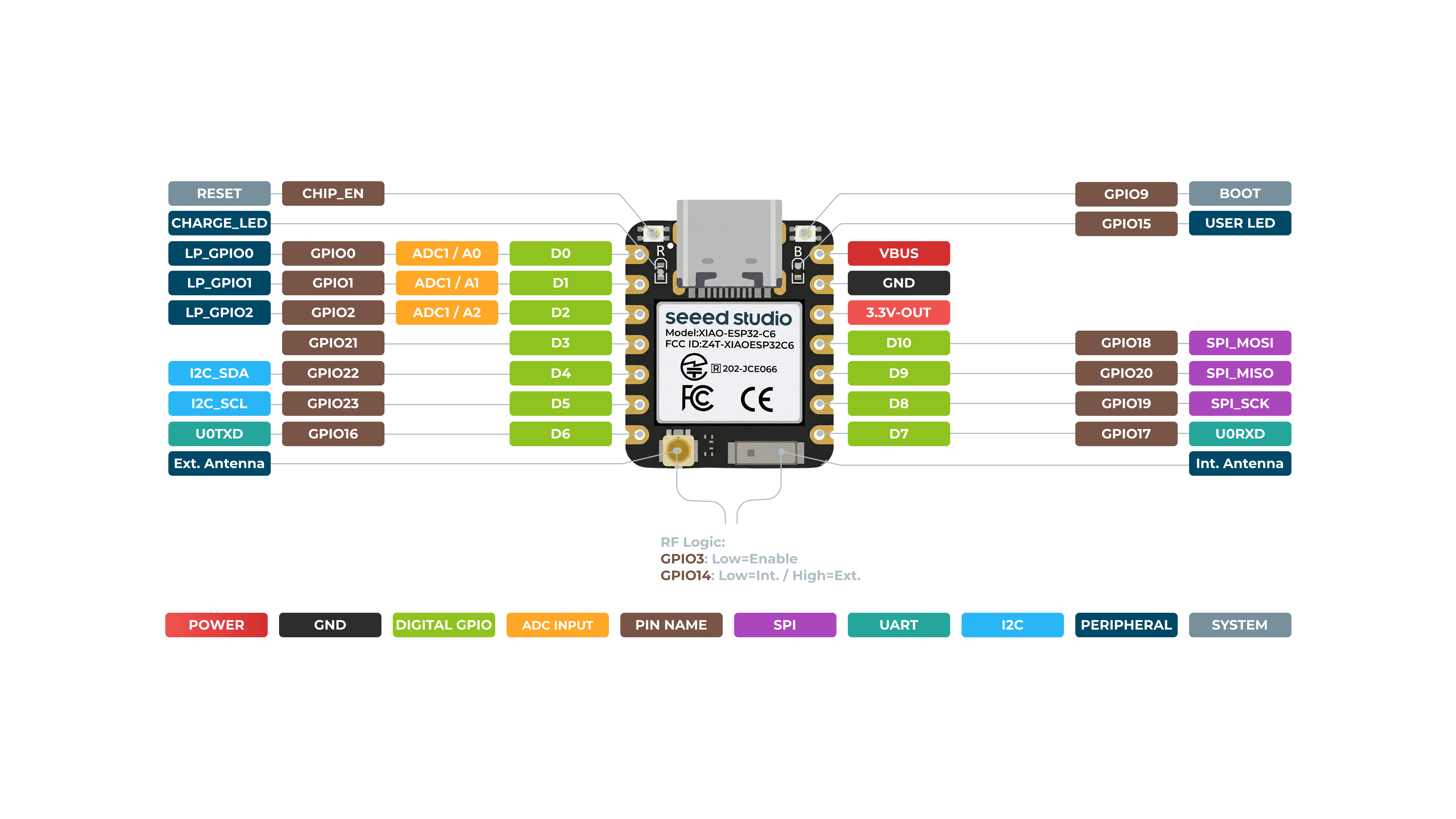
在开始之前,让我们先通过下图示意图回顾一下 XIAO ESP32C6 拥有的所有引脚及其功能。
正面
背面
- 5V - 这是来自 USB 端口的 5V 输出。你也可以将其作为电压输入使用,但必须在外部电源和该引脚之间串联某种二极管(肖特基、信号或功率二极管),二极管阳极接电池,阴极接 5V 引脚。
- 3V3 - 这是板载稳压器的稳压输出。你可以从这里汲取 700mA 电流
- GND - 电源/数据/信号地
串行通信
在 XIAO ESP32C6 上有两种串行通信方式:software serial 和 hardware serial。软件串口常用于灵活配置,而硬件串口则提供更好的性能。
硬件连接
- 将外部设备的 TX 引脚连接到 XIAO ESP32C6 的 RX 引脚(
D7)。 - 将外部设备的 RX 引脚连接到 XIAO ESP32C6 的 TX 引脚(
D6)。
代码示例
软件串口
要使用软件串口,请安装 EspSoftwareSerial 库。
目前我们推荐使用 EspSoftwareSerial 库的 7.0.0 版本。其他版本可能存在不同程度的问题,导致软件串口无法正常工作。
#include <SoftwareSerial.h>

SoftwareSerial mySerial(D7, D6); // RX, TX

void setup() {
  Serial.begin(9600);
  mySerial.begin(9600);
}

void loop() {
  if (mySerial.available()) {
    char data = mySerial.read();
    Serial.print("Received via software serial: ");
    Serial.println(data);
  }

  if (Serial.available()) {
    char data = Serial.read();
    mySerial.print("Received via hardware serial: ");
    mySerial.println(data);
  }
}
此示例在引脚 D7 (RX) 和 D6 (TX) 上以 9600 波特率配置软件串口。它同时监视硬件串口(USB)和软件串口,并在两者之间回显接收到的数据。
硬件串口
XIAO ESP32C6 提供一个用于串行通信的硬件 UART(UART0),对应引脚为 D7/D6。
#include <HardwareSerial.h>

HardwareSerial mySerial(0); // UART0 (Serial0)

void setup() {
  Serial.begin(9600);  // USB serial
  mySerial.begin(9600); // UART0
}

void loop() {
  if (Serial.available()) {
    char data = Serial.read();
    Serial.print("Received on USB: ");
    Serial.println(data);
  }

  if (mySerial.available()) {
    char data = mySerial.read();
    Serial.print("Received on UART0: ");
    Serial.println(data);
  }
}
此示例使用硬件 UART0(Serial0)进行通信。它初始化 USB 串口和 UART0,然后同时监视两个端口的输入数据,并将接收到的消息打印到 USB 串口。
Serial1 的使用
根据上文 XIAO ESP32C6 引脚图中的具体参数,我们可以看到有 TX 引脚和 RX 引脚。 这与普通串行通信略有不同,但用法也非常相似,只是需要额外添加几个参数。 接下来,我们将使用芯片引出的这些引脚进行串行通信。
需要包含的核心函数:
Serial1.begin(BAUD,SERIAL_8N1,RX_PIN,TX_PIN);-- 使能 Serial1,函数原型为:<Serial.Type>.begin(unsigned long baud, uint32_t config, int8_t rxPin, int8_t txPin);baud:波特率config:配置位rxPin:接收引脚txPin:发送引脚
值得注意的是,如果我们使用数字引脚端口来定义,这里应为 #define RX_PIN D7、#define TX_PIN D6,具体参数请参考不同 XIAO 系列的引脚图。
下面是一个示例程序:
#define RX_PIN D7
#define TX_PIN D6
#define BAUD 115200

void setup() {
    Serial1.begin(BAUD,SERIAL_8N1,RX_PIN,TX_PIN);
}

void loop() {
  if(Serial1.available() > 0)
  {
    char incominByte = Serial1.read();
    Serial1.print("I received : ");
    Serial1.println(incominByte);
  }
  delay(1000);
}
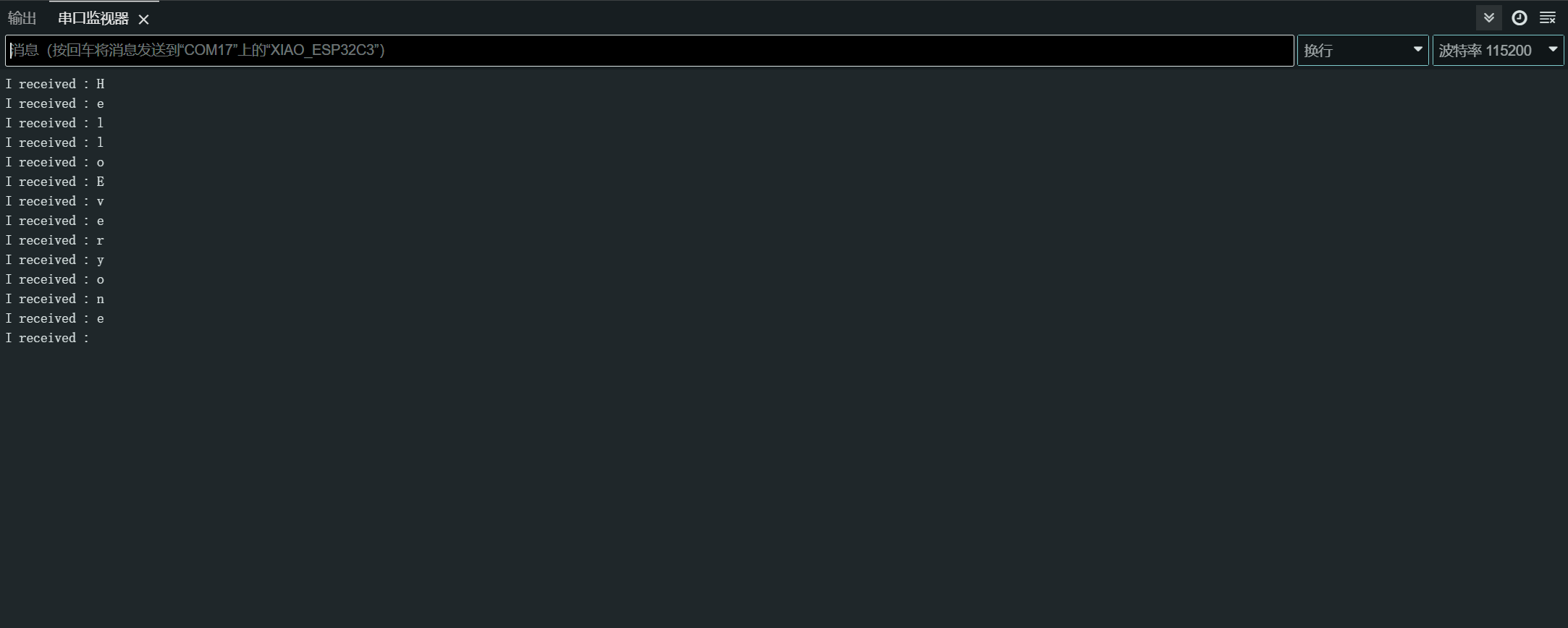
上传程序后,在 Arduino IDE 中打开串口监视器,并将波特率设置为 115200。然后,你就可以通过串口监视器向 XIAO ESP32C6 发送你想要的内容,XIAO 会逐字节打印出你发送的内容。在这里,我输入的内容是 “Hello Everyone”,我的结果示意图如下:
数字 I/O
XIAO ESP32C6 具有 12 个 GPIO 引脚,你可以将其配置为输入或输出。
硬件准备
- 将一个按键连接到引脚
D1:- 使用一个外部上拉电阻(如果使用内部上拉电阻则可选)。
- 将一个 LED 连接到引脚
D10:- 与 LED 串联一个限流电阻。
软件实现
GPIO API 提供了用于配置和操作 GPIO 引脚的函数。更多细节请参考 GPIO API 文档。
const int buttonPin = D1; // Button pin
const int ledPin = D10; // LED pin

void setup() {
  pinMode(ledPin, OUTPUT); // Set LED pin as output
  pinMode(buttonPin, INPUT); // Set button pin as input
  // If not using an external pull-up resistor
  pinMode(buttonPin, INPUT_PULLUP); // Enable internal pull-up resistor
}

void loop() {
  int buttonState = digitalRead(buttonPin); // Read button state
  digitalWrite(ledPin, buttonState); // Write button state to LED
}
中断方式
你也可以使用中断来更高效地处理按键按下事件。
// Define the pin numbers for the button and LED
const int buttonPin = D1;
const int ledPin = D10;

// Define a structure to hold button-related data
struct Button {
    const uint8_t PIN; // Pin number for the button
    uint32_t numberKeyPresses; // Counter for the number of button presses
    bool pressed; // Flag to indicate if the button is currently pressed
};

// Create an instance of the Button structure for the button
Button my_button = {buttonPin, 0, false};

// Interrupt Service Routine (ISR) to handle button presses
void ARDUINO_ISR_ATTR isr(void* arg) {
    Button* s = static_cast<Button*>(arg); // Cast the argument to a Button pointer
    s->numberKeyPresses += 1; // Increment the number of button presses
    s->pressed = true; // Set the pressed flag
}

void setup() {
    Serial.begin(115200);
    pinMode(my_button.PIN, INPUT_PULLUP); // Set the button pin as input with internal pull-up resistor
    attachInterruptArg(my_button.PIN, isr, &my_button, FALLING); // Attach the ISR to the button pin, triggered on falling edge
}

void loop() {
    if (my_button.pressed) { // Check if the button is pressed
        Serial.printf("Button 1 has been pressed %lu times\n", my_button.numberKeyPresses); // Print the number of button presses
        my_button.pressed = false; // Reset the pressed flag
    }

    static uint32_t lastMillis = 0; // Variable to store the last time the interrupt was detached
    if (millis() - lastMillis > 10000) { // Check if 10 seconds have elapsed
        lastMillis = millis(); // Update the last detach time
        detachInterrupt(my_button.PIN); // Detach the interrupt from the button pin
    }
}
在这个示例中,我们使用一个 Button 结构体来保存与按键相关的数据,包括引脚编号、按键按下次数以及一个用于指示按键当前是否被按下的标志位。
isr 函数是一个中断服务程序(ISR),用于处理按键按下事件。它会增加按键按下的次数计数,并将按下标志设置为 true。
在 setup 函数中,我们初始化串行通信,将按键引脚设置为带内部上拉电阻的输入模式,并将 isr 函数附加到按键引脚上,作为在下降沿(按键按下)触发的中断处理函数。
在 loop 函数中,我们检查按键是否被按下。如果是,则在串口监视器中打印按键按下的次数,并重置按下标志。此外,我们还加入了一段逻辑,每隔 10 秒从按键引脚上分离中断处理函数,大概是为了留出时间执行其他操作或防止意外中断。
好的,明白了。下面是改写后更易理解的版本:
ADC - 模数转换器
XIAO ESP32C6 具有多个模拟输入引脚,可用于读取模拟电压。
有关更多详细信息,请参考 ADC API 文档。
硬件连接
- 将一个电位器连接到引脚 A0,一端连接到 3.3V,另一端连接到 GND。
软件实现
下面是一个读取模拟值的 Arduino 示例程序:
const int analogPin = A0;

void setup() {
  // Initialize serial communication at 115200 bits per second
  Serial.begin(115200);

  // Set the resolution to 12 bits (0-4095)
  analogReadResolution(12);
}

void loop() {
  // Read the analog value and millivolts for the analogPin
  int analogValue = analogRead(analogPin);
  int analogVolts = analogReadMilliVolts(analogPin);

  // Print the values to the Serial Monitor
  Serial.printf("ADC analog value = %d\n", analogValue);
  Serial.printf("ADC millivolts value = %d\n", analogVolts);

  delay(100); // Delay for clear reading from serial
}
这段代码从指定引脚读取模拟值,并将其与对应的毫伏值一起打印到串口监视器。
PWM 信号 / LED 控制
XIAO ESP32-C6 具有 6 个 LEDC 通道,可以生成相互独立的波形,例如可用于驱动 RGB LED 设备。
有关更多详细信息,请参考 LEDC API 文档。
硬件连接
- 将一个 LED 通过限流电阻串联后连接到引脚
D2。
软件实现
下面是一些演示 PWM 输出的 Arduino 示例程序:
通用 PWM
const int ledPin = D2;

void setup() {
  pinMode(ledPin, OUTPUT);
}

void loop() {
  for (int dutyCycle = 0; dutyCycle <= 255; dutyCycle++) {
    analogWrite(ledPin, dutyCycle);
    delay(10);
  }
}
这段代码通过 PWM 逐渐增加 LED 的亮度。
LED 控制
/*
 LEDC Software Fade

 This example shows how to software fade an LED
 using the ledcWrite function.

 Code adapted from the original Arduino Fade example:
 https://www.arduino.cc/en/Tutorial/Fade

 This example code is in the public domain.
 */

// Use 12-bit precision for the LEDC timer
#define LEDC_TIMER_12_BIT  12

// Use 5000 Hz as the LEDC base frequency
#define LEDC_BASE_FREQ     5000

// Fade LED PIN (replace with LED_BUILTIN constant for the built-in LED)
#define LED_PIN            D5

int brightness = 0;    // How bright the LED is
int fadeAmount = 5;    // How many points to fade the LED by

// Arduino-like analogWrite
// Value has to be between 0 and valueMax
void ledcAnalogWrite(uint8_t pin, uint32_t value, uint32_t valueMax = 255) {
  // Calculate duty, 4095 from 2 ^ 12 - 1
  uint32_t duty = (4095 / valueMax) * min(value, valueMax);

  // Write duty to LEDC
  ledcWrite(pin, duty);
}

void setup() {
  // Setup timer and attach timer to the LED pin
  ledcAttach(LED_PIN, LEDC_BASE_FREQ, LEDC_TIMER_12_BIT);
}

void loop() {
  // Set the brightness on the LEDC channel
  ledcAnalogWrite(LED_PIN, brightness);

  // Change the brightness for the next loop iteration
  brightness = brightness + fadeAmount;

  // Reverse the direction of the fading at the ends of the fade
  if (brightness <= 0 || brightness >= 255) {
    fadeAmount = -fadeAmount;
  }
  // Wait for 30 milliseconds to see the dimming effect
  delay(30);
}
这段代码演示了如何使用 ledcWrite 函数实现 LED 的渐亮渐灭。LED 亮度在一个连续循环中逐渐增加和减小。
I2C
XIAO ESP32C6 具有硬件 I2C 接口,用于与 I2C 设备通信。
有关更多详细信息,请参考 I2C API 文档。
硬件准备
- 将 I2C 设备的 SDA 引脚连接到 XIAO 的 SDA 引脚(
D4)。 - 将 I2C 设备的 SCL 引脚连接到 XIAO 的 SCL 引脚(
D5)。
软件实现
主机模式
下面是一个演示从 I2C 传感器读取数据的 Arduino 示例程序:
#include <Wire.h>

const int sensorAddress = 0x40;

void setup() {
  Wire.begin();
  Serial.begin(115200);
}

void loop() {
  Wire.beginTransmission(sensorAddress);
  Wire.write(0x01);  // Register address
  Wire.endTransmission();

  Wire.requestFrom(sensorAddress, 2);
  if (Wire.available() >= 2) {
    int data = Wire.read() << 8 | Wire.read();
    Serial.println(data);
  }

  delay(100);
}
这段代码从 I2C 传感器的寄存器 0x01 中读取一个 16 位的数值。
从机模式
下面是一个演示将 XIAO ESP32C6 用作 I2C 从设备 的 Arduino 示例程序:
#include "Wire.h"

#define I2C_DEV_ADDR 0x55

uint32_t i = 0;

void onRequest() {
  Wire.print(i++);
  Wire.print(" Packets.");
  Serial.println("onRequest");
}

void onReceive(int len) {
  Serial.printf("onReceive[%d]: ", len);
  while (Wire.available()) {
    Serial.write(Wire.read());
  }
  Serial.println();
}

void setup() {
  Serial.begin(115200);
  Serial.setDebugOutput(true);
  Wire.onReceive(onReceive);
  Wire.onRequest(onRequest);
  Wire.begin((uint8_t)I2C_DEV_ADDR);

#if CONFIG_IDF_TARGET_ESP32
  char message[64];
  snprintf(message, 64, "%lu Packets.", i++);
  Wire.slaveWrite((uint8_t *)message, strlen(message));
#endif
}

void loop() {
  // Slave device code here
}
在这个从机模式示例中,XIAO ESP32C6 被配置为地址为 0x55 的 I2C 从设备。当从机从主机接收到数据时,会调用 onReceive 回调函数;当主机向从机请求数据时,会调用 onRequest 回调函数。
SPI
XIAO ESP32C6 微控制器板载有 SPI 接口,可实现与其他 SPI 兼容设备之间的高速数据交换。这在需要多个设备之间快速通信的项目中尤其有用。
- 有关详细技术规格,请参考 XIAO ESP32C6 数据手册。
- 要了解更多如何在 XIAO ESP32C6 上使用 SPI 接口的信息,请查阅 SPI API 文档。
硬件准备
要将 XIAO ESP32C6 连接到另一个 SPI 设备,请按照以下步骤操作:
- MOSI(主出从入): 将 SPI 设备的
MOSI引脚连接到 XIAO 的D10引脚。 - MISO(主入从出): 将 SPI 设备的
MISO引脚连接到 XIAO 的D9引脚。 - SCK(串行时钟): 将 SPI 设备的
SCK引脚连接到 XIAO 的D8引脚。 - CS(片选): 将 SPI 设备的
CS引脚连接到 XIAO 的某个数字引脚(例如D3)。
MOSI -> D10
MISO -> D9
SCK -> D8
CS -> D3 (as an example)
软件实现
下面是一个简化的 Arduino 示例程序,演示了使用 XIAO ESP32C6 与 SPI 设备进行基本 SPI 通信。该示例向 SPI 设备发送一条命令,并读取返回的响应(从 SPI 设备读取数据)。
#include <SPI.h>

const int csPin = 3;  // Use pin D3 for Chip Select (CS)

void setup() {
  // Initialize SPI communication
  SPI.begin();
  // Set the CS pin as an output
  pinMode(csPin, OUTPUT);
  // Set the CS pin high to indicate no active communication
  digitalWrite(csPin, HIGH);
}

void loop() {
  // Start communication with the device
  digitalWrite(csPin, LOW);
  SPI.transfer(0x01);  // Send a command to the device
  int data = SPI.transfer(0);  // Read the response
  digitalWrite(csPin, HIGH);  // End communication

  // Print the received data
  Serial.println(data);
  delay(100);  // Wait for a short period
}
请确保示例程序中的引脚分配与硬件连接中的实际引脚一致。上述示例使用了基于 XIAO ESP32-C6 的 pin_arduino.h 文件中预定义的引脚编号,并额外定义了 CS 引脚。