使用 Seeed Studio XIAO ESP32C6 进行 Arduino 编程
| Seeed Studio XIAO ESP32C6 |
|---|
 |
Seeed Studio XIAO ESP32C6 由高度集成的 ESP32-C6 SoC 驱动,基于两个 32 位 RISC-V 处理器构建,包含一个运行频率高达 160 MHz 的高性能 (HP) 处理器,以及一个可时钟频率高达 20 MHz 的低功耗 (LP) 32 位 RISC-V 处理器。芯片上有 512KB SRAM 和 4 MB Flash,提供更多编程空间,为物联网控制场景带来更多可能性。
入门指南
引脚概览
在开始之前,让我们通过以下原理图回顾 XIAO ESP32C6 的所有引脚及其功能。
| XIAO ESP32C6/XIAO ESP32C6 指示图 |
|---|
| XIAO ESP32C6/XIAO ESP32C6 Sense 引脚列表 |
- 5V - 这是来自USB端口的5V输出。您也可以将其用作电压输入,但必须在外部电源和此引脚之间使用某种二极管(肖特基、信号、功率),阳极连接电池,阴极连接5V引脚。
- 3V3 - 这是板载稳压器的稳压输出。您可以获得700mA的电流
- GND - 电源/数据/信号地
串行通信
与XIAO ESP32C6进行串行通信有两种方法:软件串口和硬件串口。软件串口通常用于灵活性,而硬件串口提供更好的性能。
硬件设置
- 将外部设备的TX引脚连接到XIAO ESP32C6的RX引脚(
D7)。 - 将外部设备的RX引脚连接到XIAO ESP32C6的TX引脚(
D6)。
代码示例
软件串口
要使用软件串口,请安装EspSoftwareSerial库。
目前我们推荐使用EspSoftwareSerial库的7.0.0版本。其他版本可能存在不同程度的问题,导致软串口无法正常工作。
#include <SoftwareSerial.h>

SoftwareSerial mySerial(D7, D6); // RX, TX

void setup() {
  Serial.begin(9600);
  mySerial.begin(9600);
}

void loop() {
  if (mySerial.available()) {
    char data = mySerial.read();
    Serial.print("Received via software serial: ");
    Serial.println(data);
  }

  if (Serial.available()) {
    char data = Serial.read();
    mySerial.print("Received via hardware serial: ");
    mySerial.println(data);
  }
}
这个示例在引脚 D7 (RX) 和 D6 (TX) 上设置软件串口,波特率为 9600。它监控硬件串口(USB)和软件串口端口,在它们之间回显接收到的数据。
硬件串口
XIAO ESP32C6 具有用于串口通信的硬件 UART(UART0),对应引脚 D7/D6。
#include <HardwareSerial.h>

HardwareSerial mySerial(0); // UART0 (Serial0)

void setup() {
  Serial.begin(9600);  // USB serial
  mySerial.begin(9600); // UART0
}

void loop() {
  if (Serial.available()) {
    char data = Serial.read();
    Serial.print("Received on USB: ");
    Serial.println(data);
  }

  if (mySerial.available()) {
    char data = mySerial.read();
    Serial.print("Received on UART0: ");
    Serial.println(data);
  }
}
这个示例使用硬件 UART0 (Serial0) 进行通信。它初始化 USB 串口和 UART0,然后监控两个端口的传入数据,将接收到的消息打印到 USB 串口端口。
Serial1 使用方法
根据上述 XIAO ESP32C6 引脚图的具体参数,我们可以观察到有 TX 引脚和 RX 引脚。 这与串口通信不同,但使用方法也非常相似,只是需要添加一些参数。 接下来,我们将使用芯片引出的引脚进行串口通信。
需要包含的核心函数:
Serial1.begin(BAUD,SERIAL_8N1,RX_PIN,TX_PIN);-- 启用 Serial1,函数原型:<Serial.Type>.begin(unsigned long baud, uint32_t config, int8_t rxPin, int8_t txPin);baud:波特率config:配置位rxPin:接收引脚txPin:发送引脚
值得注意的是,如果我们使用数字引脚端口来定义,这里应该是 #define RX_PIN D7、#define TX_PIN D6,具体参数请参考不同 XIAO 系列的引脚图。
以下是一个示例程序:
#define RX_PIN D7
#define TX_PIN D6
#define BAUD 115200

void setup() {
    Serial1.begin(BAUD,SERIAL_8N1,RX_PIN,TX_PIN);
}

void loop() {
  if(Serial1.available() > 0)
  {
    char incominByte = Serial1.read();
    Serial1.print("I received : ");
    Serial1.println(incominByte);
  }
  delay(1000);
}
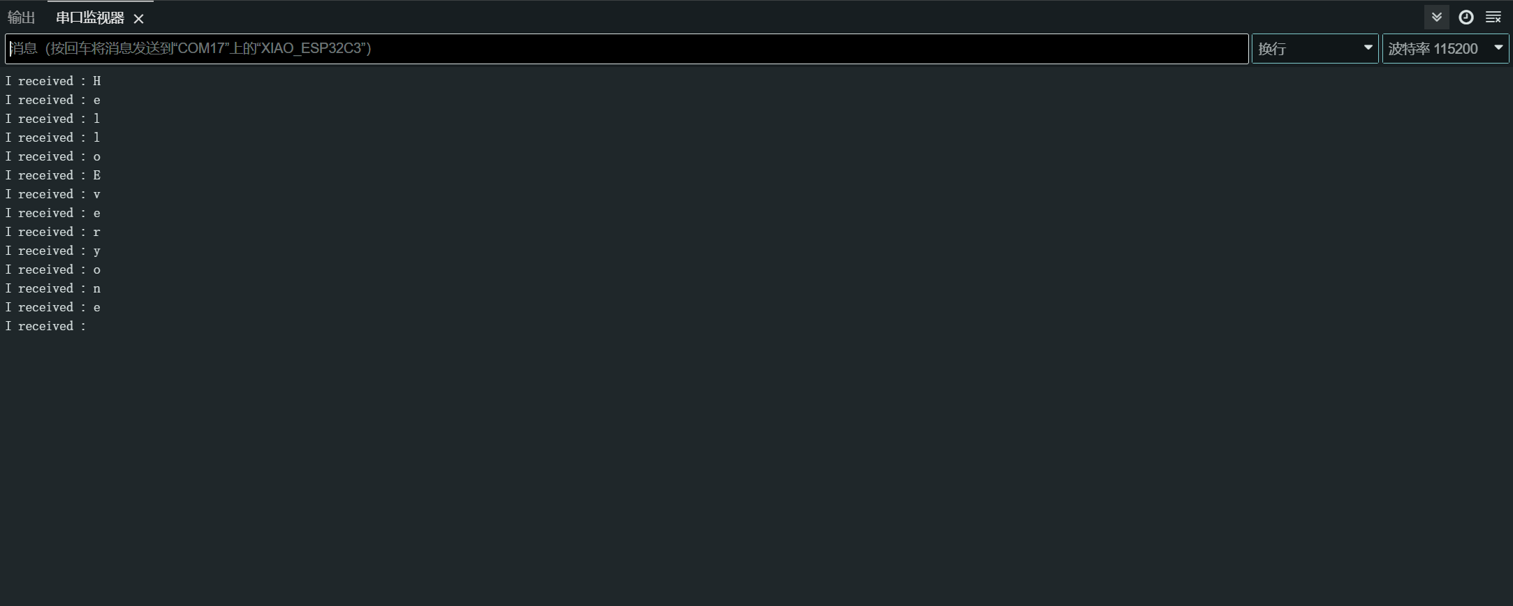
上传程序后,在Arduino IDE中打开串口监视器并将波特率设置为115200。然后,你可以通过串口监视器向XIAO ESP32C6发送你想要的内容,XIAO将打印出你发送内容的每个字节。在这里,我输入的内容是"Hello Everyone",我的结果图表如下所示
数字I/O
XIAO ESP32C6有12个GPIO引脚,你可以将其配置为输入或输出。
硬件准备
- 将按钮连接到引脚
D1:- 使用外部上拉电阻(如果使用内部上拉电阻则可选)。
- 将LED连接到引脚
D10:- 在LED串联中包含一个限流电阻。
软件实现
GPIO API提供了配置和与GPIO引脚交互的函数。有关更多详细信息,请参阅GPIO API文档。
const int buttonPin = D1; // Button pin
const int ledPin = D10; // LED pin

void setup() {
  pinMode(ledPin, OUTPUT); // Set LED pin as output
  pinMode(buttonPin, INPUT); // Set button pin as input
  // If not using an external pull-up resistor
  pinMode(buttonPin, INPUT_PULLUP); // Enable internal pull-up resistor
}

void loop() {
  int buttonState = digitalRead(buttonPin); // Read button state
  digitalWrite(ledPin, buttonState); // Write button state to LED
}
Interrupt Method
您还可以使用中断来更高效地处理按钮按压。
// Define the pin numbers for the button and LED
const int buttonPin = D1;
const int ledPin = D10;

// Define a structure to hold button-related data
struct Button {
    const uint8_t PIN; // Pin number for the button
    uint32_t numberKeyPresses; // Counter for the number of button presses
    bool pressed; // Flag to indicate if the button is currently pressed
};

// Create an instance of the Button structure for the button
Button my_button = {buttonPin, 0, false};

// Interrupt Service Routine (ISR) to handle button presses
void ARDUINO_ISR_ATTR isr(void* arg) {
    Button* s = static_cast<Button*>(arg); // Cast the argument to a Button pointer
    s->numberKeyPresses += 1; // Increment the number of button presses
    s->pressed = true; // Set the pressed flag
}

void setup() {
    Serial.begin(115200);
    pinMode(my_button.PIN, INPUT_PULLUP); // Set the button pin as input with internal pull-up resistor
    attachInterruptArg(my_button.PIN, isr, &my_button, FALLING); // Attach the ISR to the button pin, triggered on falling edge
}

void loop() {
    if (my_button.pressed) { // Check if the button is pressed
        Serial.printf("Button 1 has been pressed %lu times\n", my_button.numberKeyPresses); // Print the number of button presses
        my_button.pressed = false; // Reset the pressed flag
    }

    static uint32_t lastMillis = 0; // Variable to store the last time the interrupt was detached
    if (millis() - lastMillis > 10000) { // Check if 10 seconds have elapsed
        lastMillis = millis(); // Update the last detach time
        detachInterrupt(my_button.PIN); // Detach the interrupt from the button pin
    }
}
在这个例子中,我们使用一个 Button 结构来保存按钮相关的数据,包括引脚号、按键次数,以及一个标志来指示按钮当前是否被按下。
isr 函数是一个中断服务程序(ISR),用于处理按钮按下事件。它会增加按钮按下次数并将按下标志设置为 true。
在 setup 函数中,我们初始化串口通信,将按钮引脚设置为带内部上拉电阻的输入,并将 isr 函数作为中断处理程序附加到按钮引脚上,在下降沿(按钮按下)时触发。
在 loop 函数中,我们检查按钮是否被按下。如果是,我们将按钮按下次数打印到串口监视器并重置按下标志。此外,我们还包含了一个部分,每 10 秒从按钮引脚分离中断,可能是为了允许其他操作或防止意外中断。
好的,明白了。这里是重写的更易理解的版本:
ADC - 模拟数字转换器
XIAO ESP32C6 有几个模拟输入引脚,允许读取模拟电压。
请参考 ADC API 文档了解更多详情。
硬件设置
- 将电位器连接到引脚 A0,一端连接到 3.3V,另一端连接到 GND。
软件实现
这里是一个读取模拟值的 Arduino 代码:
const int analogPin = A0;

void setup() {
  // Initialize serial communication at 115200 bits per second
  Serial.begin(115200);

  // Set the resolution to 12 bits (0-4095)
  analogReadResolution(12);
}

void loop() {
  // Read the analog value and millivolts for the analogPin
  int analogValue = analogRead(analogPin);
  int analogVolts = analogReadMilliVolts(analogPin);

  // Print the values to the Serial Monitor
  Serial.printf("ADC analog value = %d\n", analogValue);
  Serial.printf("ADC millivolts value = %d\n", analogVolts);

  delay(100); // Delay for clear reading from serial
}
这段代码从指定引脚读取模拟值并将其与毫伏值一起打印到串行监视器。
PWM 信号 / LED 控制
XIAO ESP32-C6 有 6 个 LEDC 通道,可以生成独立的波形,例如可用于驱动 RGB LED 设备。
有关更多详细信息,请参阅 LEDC API 文档。
硬件设置
- 将 LED 连接到引脚
D2,并串联一个限流电阻。
软件实现
以下是演示 PWM 输出的 Arduino 代码:
通用 PWM
const int ledPin = D2;

void setup() {
  pinMode(ledPin, OUTPUT);
}

void loop() {
  for (int dutyCycle = 0; dutyCycle <= 255; dutyCycle++) {
    analogWrite(ledPin, dutyCycle);
    delay(10);
  }
}
这段代码使用PWM逐步增加LED的亮度。
LED Control
/*
 LEDC Software Fade

 This example shows how to software fade an LED
 using the ledcWrite function.

 Code adapted from the original Arduino Fade example:
 https://www.arduino.cc/en/Tutorial/Fade

 This example code is in the public domain.
 */

// Use 12-bit precision for the LEDC timer
#define LEDC_TIMER_12_BIT  12

// Use 5000 Hz as the LEDC base frequency
#define LEDC_BASE_FREQ     5000

// Fade LED PIN (replace with LED_BUILTIN constant for the built-in LED)
#define LED_PIN            D5

int brightness = 0;    // How bright the LED is
int fadeAmount = 5;    // How many points to fade the LED by

// Arduino-like analogWrite
// Value has to be between 0 and valueMax
void ledcAnalogWrite(uint8_t pin, uint32_t value, uint32_t valueMax = 255) {
  // Calculate duty, 4095 from 2 ^ 12 - 1
  uint32_t duty = (4095 / valueMax) * min(value, valueMax);

  // Write duty to LEDC
  ledcWrite(pin, duty);
}

void setup() {
  // Setup timer and attach timer to the LED pin
  ledcAttach(LED_PIN, LEDC_BASE_FREQ, LEDC_TIMER_12_BIT);
}

void loop() {
  // Set the brightness on the LEDC channel
  ledcAnalogWrite(LED_PIN, brightness);

  // Change the brightness for the next loop iteration
  brightness = brightness + fadeAmount;

  // Reverse the direction of the fading at the ends of the fade
  if (brightness <= 0 || brightness >= 255) {
    fadeAmount = -fadeAmount;
  }
  // Wait for 30 milliseconds to see the dimming effect
  delay(30);
}
这段代码演示了如何使用 ledcWrite 函数来淡化 LED。LED 亮度在连续循环中逐渐增加和减少。
I2C
XIAO ESP32C6 具有硬件 I2C 接口,用于与 I2C 设备通信。
请参考 I2C API 文档了解更多详情。
硬件准备
- 将 I2C 设备的 SDA 引脚连接到 XIAO 的 SDA 引脚(
D4)。 - 将 I2C 设备的 SCL 引脚连接到 XIAO 的 SCL 引脚(
D5)。
软件实现
主机模式
以下是一个演示从 I2C 传感器读取数据的 Arduino 示例:
#include <Wire.h>

const int sensorAddress = 0x40;

void setup() {
  Wire.begin();
  Serial.begin(115200);
}

void loop() {
  Wire.beginTransmission(sensorAddress);
  Wire.write(0x01);  // Register address
  Wire.endTransmission();

  Wire.requestFrom(sensorAddress, 2);
  if (Wire.available() >= 2) {
    int data = Wire.read() << 8 | Wire.read();
    Serial.println(data);
  }

  delay(100);
}
这段代码从I2C传感器的寄存器0x01读取一个16位值。
从机模式
以下是一个Arduino示例代码,演示如何将XIAO ESP32C6用作I2C从设备:
#include "Wire.h"

#define I2C_DEV_ADDR 0x55

uint32_t i = 0;

void onRequest() {
  Wire.print(i++);
  Wire.print(" Packets.");
  Serial.println("onRequest");
}

void onReceive(int len) {
  Serial.printf("onReceive[%d]: ", len);
  while (Wire.available()) {
    Serial.write(Wire.read());
  }
  Serial.println();
}

void setup() {
  Serial.begin(115200);
  Serial.setDebugOutput(true);
  Wire.onReceive(onReceive);
  Wire.onRequest(onRequest);
  Wire.begin((uint8_t)I2C_DEV_ADDR);

#if CONFIG_IDF_TARGET_ESP32
  char message[64];
  snprintf(message, 64, "%lu Packets.", i++);
  Wire.slaveWrite((uint8_t *)message, strlen(message));
#endif
}

void loop() {
  // Slave device code here
}
在这个从机模式示例中,XIAO ESP32C6 被配置为地址为 0x55 的 I2C 从设备。当从机从主机接收数据时会调用 onReceive 回调函数,当主机从从机请求数据时会调用 onRequest 回调函数。
SPI
XIAO ESP32C6 微控制器开发板具有内置的 SPI 接口,便于与其他 SPI 兼容设备进行快速数据交换。这在需要多个设备之间快速通信的项目中特别有用。
- 有关详细的技术规格,请参考 XIAO ESP32C6 数据手册。
- 通过查阅 SPI API 文档 了解更多关于如何在 XIAO ESP32C6 上使用 SPI 接口的信息。
硬件准备
要将您的 XIAO ESP32C6 连接到另一个 SPI 设备,请按照以下步骤操作:
- MOSI (主机输出从机输入): 将 SPI 设备的
MOSI引脚连接到 XIAO 的D10引脚。 - MISO (主机输入从机输出): 将 SPI 设备的
MISO引脚连接到 XIAO 的D9引脚。 - SCK (串行时钟): 将 SPI 设备的
SCK引脚连接到 XIAO 的D8引脚。 - CS (片选): 将 SPI 设备的
CS引脚连接到 XIAO 的数字引脚(例如D3)。
MOSI -> D10
MISO -> D9
SCK -> D8
CS -> D3 (as an example)
软件实现
下面是一个简化的Arduino示例代码,演示了使用XIAO ESP32C6与SPI设备进行基本SPI通信。此示例代码向SPI设备发送命令并读取响应(从SPI设备读取数据)。
#include <SPI.h>

const int csPin = 3;  // Use pin D3 for Chip Select (CS)

void setup() {
  // Initialize SPI communication
  SPI.begin();
  // Set the CS pin as an output
  pinMode(csPin, OUTPUT);
  // Set the CS pin high to indicate no active communication
  digitalWrite(csPin, HIGH);
}

void loop() {
  // Start communication with the device
  digitalWrite(csPin, LOW);
  SPI.transfer(0x01);  // Send a command to the device
  int data = SPI.transfer(0);  // Read the response
  digitalWrite(csPin, HIGH);  // End communication

  // Print the received data
  Serial.println(data);
  delay(100);  // Wait for a short period
}
确保您的代码中的引脚分配与硬件设置中的物理连接相匹配。上述示例使用基于 XIAO ESP32-C6 的 pin_arduino.h 文件的预定义引脚号,并为 CS 引脚添加了额外定义。