使用 Seeed Studio XIAO RA4M1 进行引脚复用
硬件概述
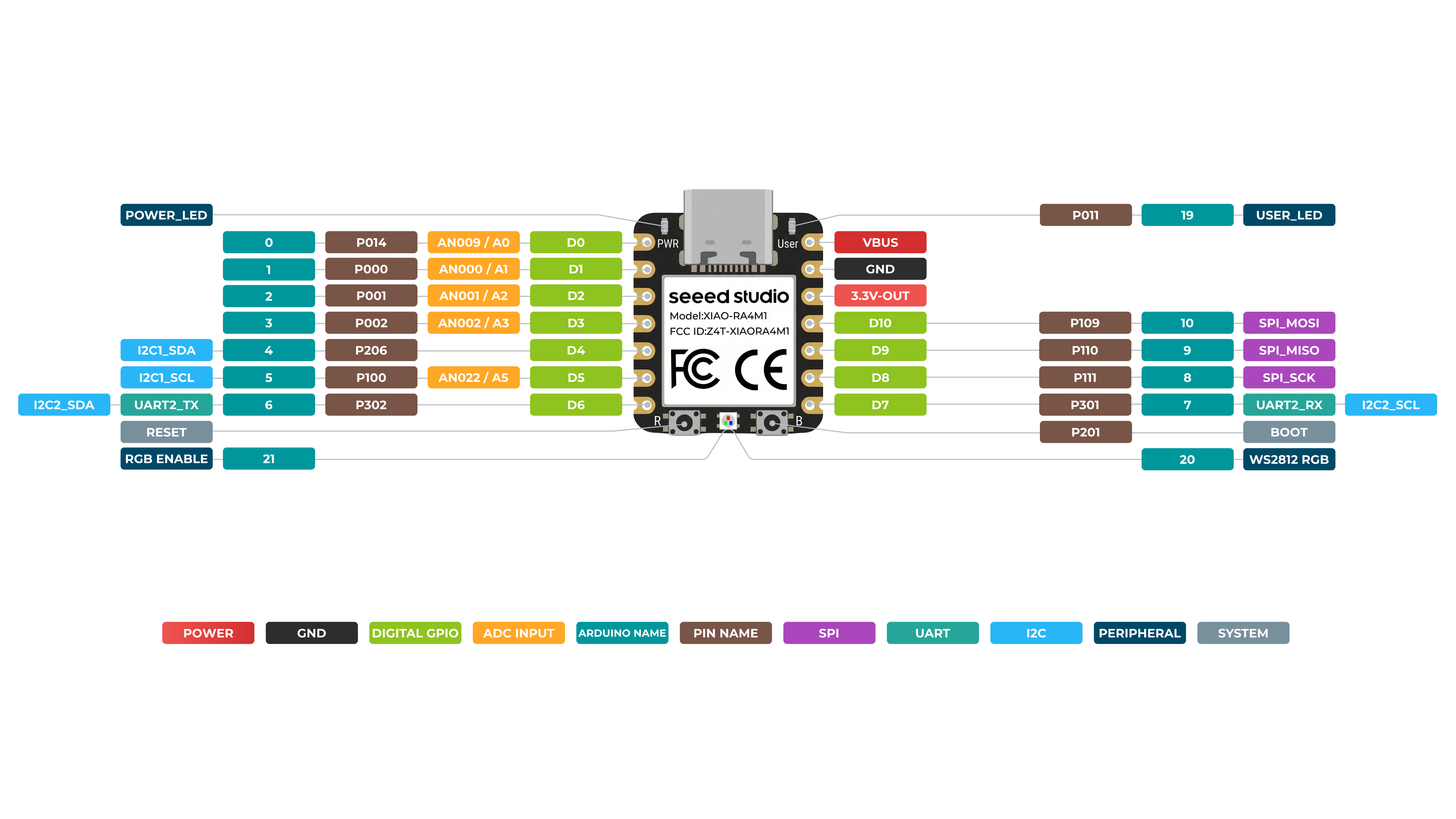
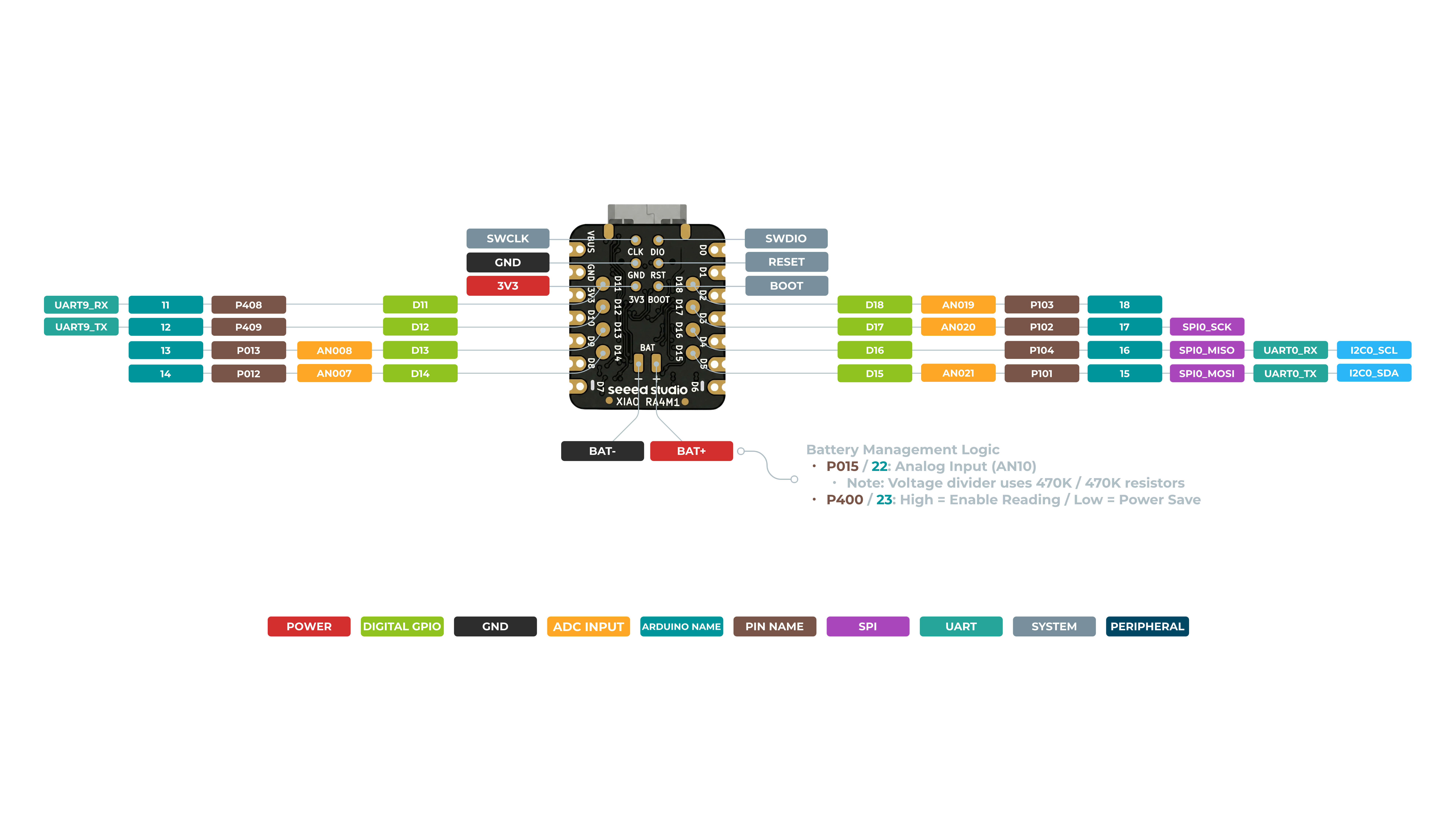
在开始之前,了解一些产品的基本参数非常重要。下表提供了 Seeed Studio XIAO RA4M1 的特性信息。
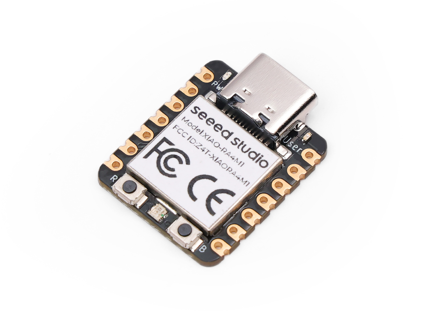
正面
背面
数字引脚
XIAO RA4M1 具有多达 11 个常规 GPIO 引脚、6 个模拟引脚以及 8 个可复用 IO 端口。在本示例中,我们将使用 XIAO RA4M1、XIAO 扩展板和一个继电器,演示如何使用不同的数字引脚进行读写。
硬件准备
| Seeed Studio XIAO R4M1 | Seeed Studio Expansion Base for XIAO with Grove OLED | Grove - Relay |
|---|---|---|
 |  |  |
请将 XIAO RA4M1 或 Sense 安装到扩展板上,并通过 Grove 线缆将继电器连接到扩展板的 A0/D0 接口。最后,通过 USB-C 线缆将 XIAO 连接到电脑。
软件实现
在本示例中,我们将通过连接到 XIAO 扩展板的按键来控制继电器的开关状态。当按下按键时,继电器吸合;当松开按键时,继电器断开。
const int buttonPin = D1;     // the number of the pushbutton pin
int buttonState = 0;          // variable for reading the pushbutton status
const int relayPin = D0;

void setup() {
  // initialize the Relay pin as an output:
  pinMode(relayPin, OUTPUT);
  // initialize the pushbutton pin as an input:
  pinMode(buttonPin, INPUT_PULLUP);
}

void loop() {
  // read the state of the pushbutton value:
  buttonState = digitalRead(buttonPin);

  // check if the pushbutton is pressed. If it is, the buttonState is HIGH:
  if (buttonState == HIGH) {
    // turn Relay on:
    digitalWrite(relayPin, HIGH);
  } else {
    // turn Relay off:
    digitalWrite(relayPin, LOW);
  }
}
如果一切顺利,在上传程序后,你应该能看到如下效果。
数字引脚作为 PWM 使用
XIAO RA4M1 上的所有 GPIO 引脚都支持 PWM 输出。因此,你可以使用任意引脚输出 PWM,用于调节灯光亮度、控制舵机等功能。
硬件准备
| Seeed Studio XIAO RA4M1 | Seeed Studio Expansion Base for XIAO with Grove OLED | Grove - Variable Color LED |
|---|---|---|
| |  |
请将 XIAO RA4M1 或 Sense 安装到扩展板上,然后使用 Grove 线缆将 Variable Color LED 连接到扩展板的 A0/D0 接口。最后,通过 USB-C 线缆将 XIAO 连接到电脑。
软件实现
在本示例中,我们将演示如何使用 PWM 输出来控制灯光的亮度。
int LED_pin = D0;    // LED connected to digital pin 10

void setup() {
  // declaring LED pin as output
  pinMode(LED_pin, OUTPUT);
}

void loop() {
  // fade in from min to max in increments of 5 points:
  for (int fadeValue = 0 ; fadeValue <= 255; fadeValue += 3) {
    // sets the value (range from 0 to 255):
    analogWrite(LED_pin, fadeValue);
    // wait for 30 milliseconds to see the dimming effect
    delay(30);
  }

  // fade out from max to min in increments of 5 points:
  for (int fadeValue = 255 ; fadeValue >= 0; fadeValue -= 3) {
    // sets the value (range from 0 to 255):
    analogWrite(LED_pin, fadeValue);
    // wait for 30 milliseconds to see the dimming effect
    delay(30);
  }
}
如果程序运行成功,你将看到如下运行效果。
模拟引脚
XIAO RA4M1 开发板配备最高 14 位 ADC,可高分辨率读取模拟传感器数值,帮助我们获得更精确的数值。XIAO RA4M1 开发板上的模数转换器(ADC)默认分辨率为 10 位,可以提升到 12 位和 14 位,以提高模拟读数的精度。
不同 ADC 精度下的详细数据范围
- 10-bit : 0~1024
- 12-bit : 0~4096
- 14-bit : 0~16383
接下来,我们将选择两个传感器来体现 ADC 的特性。
硬件准备
| Seeed Studio XIAO RA4M1 | Grove-Variable Color LED | Grove-Rotary Angle Sensor | Seeed Studio Grove Base for XIAO |
|---|---|---|---|
| |  |  |
软件实现
#define ADC_Bit_Fourteen 14
#define ADC_Bit_Twelve 12
#define ADC_Bit_Ten 10

const int analogInPin = A1;  // Analog input pin that the potentiometer is attached to
const int analogOutPin = 9;  // Analog output pin that the LED is attached to

int sensorValue = 0;  // value read from the pot
int outputValue = 0;  // value output to the PWM (analog out)

void setup() {

  Serial.begin(115200);
  // Ten_Bite_ADC_Config(); // 10bit
  // Twelve_Bite_ADC_Config(); // 12bit
  Fourteen_Bite_ADC_Config(); // 14bit

}

void loop() {
  sensorValue = analogRead(analogInPin);
  outputValue = map(sensorValue, 0, 4095, 0, 255);
  analogWrite(analogOutPin, outputValue);

  Serial.print("sensor = ");
  Serial.print(sensorValue);
  Serial.print("\t output = ");
  Serial.println(outputValue);
  delay(100);
}

void Ten_Bite_ADC_Config() {
  analogReadResolution(ADC_Bit_Ten);
}

void Twelve_Bite_ADC_Config() {
  analogReadResolution(ADC_Bit_Twelve);
}

void Fourteen_Bite_ADC_Config() {
  analogReadResolution(ADC_Bit_Fourteen);
}
如果一切顺利,在上传程序之后,你应该会看到如下效果。
串口
在使用 Arduino IDE 时,串口通信是许多项目中必不可少的一部分。要在 Arduino IDE 中使用串口,你需要先打开串口监视器窗口。这可以通过点击工具栏中的 Serial Monitor 图标,或者按下 Ctrl+Shift+M 快捷键来完成。
通用用法
一些常用的串口函数包括:
Serial.begin()-- 用于以指定的波特率初始化通信;Serial.print()-- 用于以可读格式向串口发送数据;Serial.write()-- 用于向串口发送二进制数据;Serial.available()-- 用于检查串口中是否有可读取的数据;Serial.read()-- 用于从串口读取一个字节的数据;Serial.flush()-- 用于等待正在发送的串口数据传输完成。
通过使用这些串口函数,你可以在 Arduino 开发板和计算机之间发送和接收数据,从而为创建交互式项目提供了许多可能性。
下面是一个示例程序:
void setup() {
  // initialize serial communication at 9600 bits per second:
  Serial.begin(9600);
}

void loop() {
  // send data to the serial port
  Serial.println("Hello World!");

  // read data from the serial port
  if (Serial.available() > 0) {
    // read the incoming byte:
    char incomingByte = Serial.read();
    // print the incoming byte to the serial monitor:
    Serial.print("I received: ");
    Serial.println(incomingByte);
  }

  // wait for a second before repeating the loop
  delay(1000);
}
Serial1 的用法
根据上面的 XIAO RA4M1 引脚图中的具体参数,我们可以看到有 TX 引脚和 RX 引脚。 这与串口通信有所不同,但用法也非常相似,只是需要添加几个参数。 所以下一步,我们将使用芯片引出的引脚进行串口通信。
#define BAUD 115200

void setup() {
    Serial1.begin(BAUD);
}

void loop() {
  if(Serial1.available() > 0)
  {
    char incominByte = Serial1.read();
    Serial1.print("I received : ");
    Serial1.println(incominByte);
  }
  delay(1000);
}
软件串口的用法
#include <SoftwareSerial.h>

SoftwareSerial mySerial(2, 3); // RX, TX

void setup() {
  // initialize serial communication
  Serial.begin(9600);
  while (!Serial);

  // initialize software serial
  mySerial.begin(9600);
}

void loop() {
  // read data from software serial
  if (mySerial.available()) {
    char data = mySerial.read();
    Serial.print("Received data: ");
    Serial.println(data);
  }

  // write data to software serial
  mySerial.print("Hello World!");

  // wait for a second before repeating the loop
  delay(1000);
}
在这个程序中,我们首先包含 SoftwareSerial.h 库以使用软件串口。然后,我们使用引脚 2 和 3 分别作为 RX 和 TX 创建一个名为 mySerial 的新的 SoftwareSerial 对象。
在 setup() 函数中,我们初始化硬件串口(Serial.begin())和软件串口(mySerial.begin())。
在 loop() 函数中,我们使用 mySerial.available() 函数检查软件串口中是否有可读取的数据。如果有,我们使用 mySerial.read() 函数读取传入的字节,并将其存储在一个名为 data 的变量中。然后,我们使用 Serial.print() 和 Serial.println() 函数在硬件串口上打印“Received data: ”,后面跟上 data 的值。
我们还使用 mySerial.print() 函数向软件串口写入 "Hello World!"。这会将数据从 XIAO 发送到连接在软件串口上的设备。
最后,我们添加一个 delay() 函数,在重复循环之前等待一秒钟。
IIC
XIAO RA4M1 具有一个 I2C 接口,可用于许多传感器的数据传输和解析,也可以用于驱动一些 OLED 屏幕。
硬件准备
| Seeed Studio XIAO RA4M1 | Seeed Studio Expansion Base for XIAO with Grove OLED |
|---|---|
| |
XIAO 扩展板上的 OLED 显示屏使用 I2C 协议,并通过板上的 I2C 电路连接到 XIAO 的 I2C 接口。因此,我们可以直接将 XIAO 插到扩展板上,并通过编程在屏幕上显示内容。
软件实现
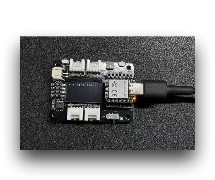
本示例介绍如何使用 Seeed Studio Expansion Base for XIAO RA4M1 上的 OLED 显示屏。
步骤 1. 将 Seeed Studio XIAO RA4M1 安装到扩展板上,然后连接 Type-C 线缆
步骤 2. 安装 u8g2 库
步骤 3. 复制代码并粘贴到 Arduino IDE 中,然后上传
#include <Arduino.h>
#include <U8x8lib.h>
#include <Wire.h>

U8X8_SSD1306_128X64_NONAME_HW_I2C u8x8(/* clock=*/ SCL, /* data=*/ SDA, /* reset=*/ U8X8_PIN_NONE);   // OLEDs without Reset of the Display

void setup(void) {
  u8x8.begin();
  u8x8.setFlipMode(1);   // set number from 1 to 3, the screen word will rotary 180
}

void loop(void) {
  u8x8.setFont(u8x8_font_chroma48medium8_r);
  u8x8.setCursor(0, 0);
  u8x8.print("i'm XIAO RA4M1");
}
在代码的前几行中,我们包含了所需的库,例如 Arduino.h、U8x8lib.h 和 Wire.h。U8x8lib.h 库提供了控制 OLED 显示屏的函数,而 Wire.h 库提供了 I2C 通信的函数。
在 setup() 函数中,我们使用 u8x8.begin() 函数初始化 OLED 显示屏。我们还使用 u8x8.setFlipMode() 函数设置显示屏的翻转模式,将屏幕旋转 180 度。
在 loop() 函数中,我们使用 u8x8.setFont() 函数设置字体,并使用 u8x8.setCursor() 函数指定显示屏上光标的位置。最后,我们使用 u8x8.print() 函数在 OLED 显示屏上显示字符串 "Hello World!"。
如果你向 XIAO RA4M1 上传程序,你会在扩展板上的 OLED 显示屏上看到显示的内容。
SPI
RA4M1 芯片集成了多种外设,其中包括一个 SPI 接口,可用于连接外部 SPI 设备,例如闪存、显示屏、传感器等。XIAO RA4M1 还支持高速 SPI 传输模式,最高 SPI 传输速率可达 80 MHz,能够满足大多数 SPI 设备的数据传输需求。
硬件准备
| Seeed Studio XIAO RA4M1 | Grove - OLED Display 1.12 (SH1107) V3.0 - SPI/IIC |
|---|---|
| _V3.0/img/10402050_Main-02.png) |
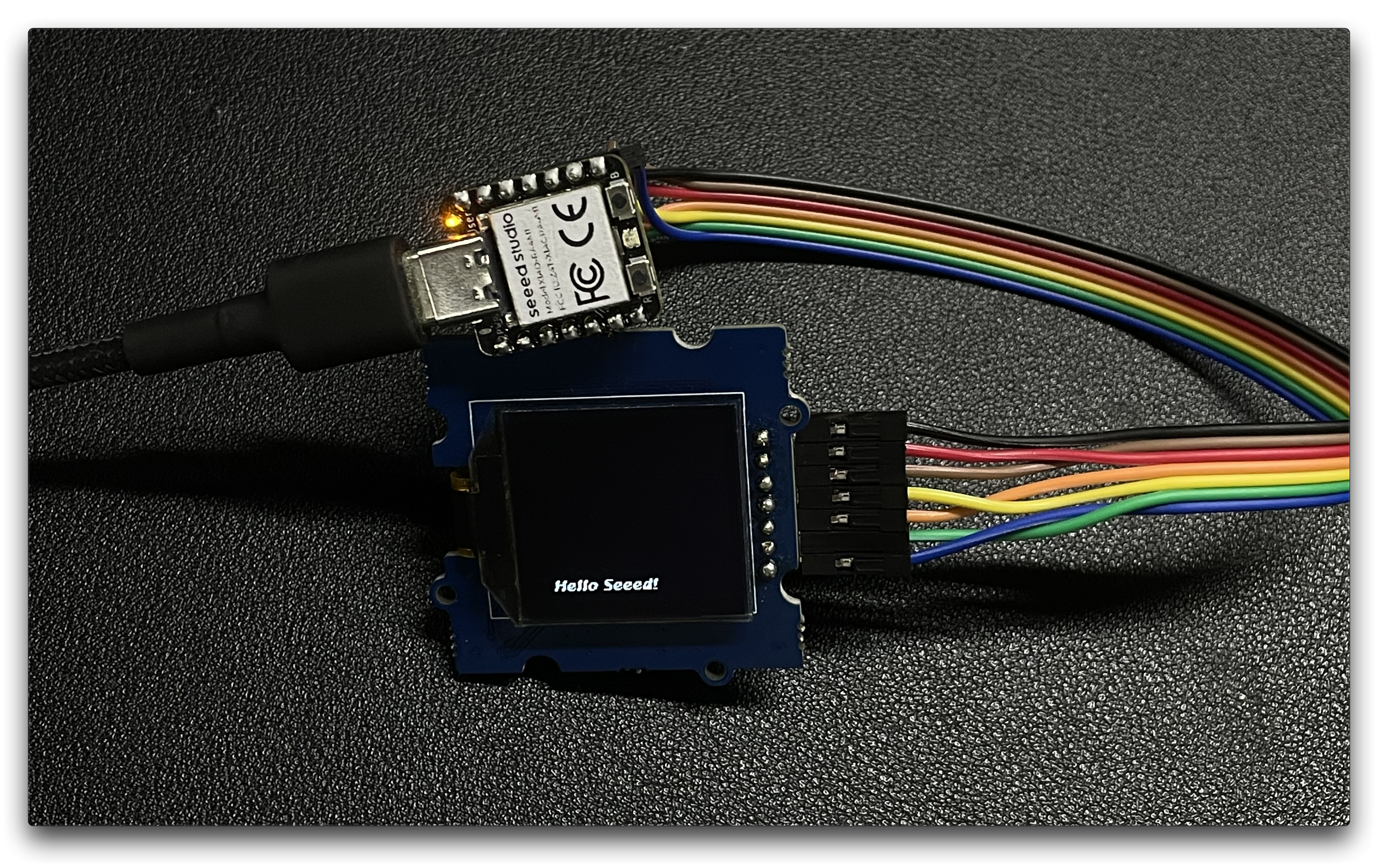
按照上述说明准备好硬件后,使用跳线将 XIAO 和 OLED 的 SPI 接口连接起来。接线方式请参考下图。
软件实现
接下来,我们将以下程序作为示例,介绍如何使用 SPI 接口控制 OLED 屏幕显示。
安装 u8g2 库。
#include <Arduino.h>
#include <U8g2lib.h>
#include <SPI.h>
#include <Wire.h>

U8G2_SH1107_128X128_1_4W_HW_SPI u8g2(U8G2_R3, /* cs=*/ D7, /* dc=*/ D4, /* reset=*/ D5);

void setup(void) {
  u8g2.begin();
}

void loop(void) {
  u8g2.firstPage();

  do {
    u8g2.setFont(u8g2_font_luBIS08_tf);
    u8g2.drawStr(0,24,"Hello Seeed!");
  } while ( u8g2.nextPage() );
}
在 setup() 函数中,使用合适的构造函数参数实例化 U8G2_SH1107_128X128_1_4W_HW_SPI 类,这些参数指定了用于片选(cs)、数据/命令(dc)和复位的引脚。然后调用 u8g2.begin() 函数来初始化显示屏。
在 loop() 函数中,使用 u8g2.firstPage()、u8g2.setFont() 和 u8g2.drawStr() 函数来更新显示内容。u8g2.firstPage() 函数用于为写入设置显示缓冲区,而 u8g2.nextPage() 用于显示更新后的内容。do-while 循环确保内容会持续显示,直到程序停止。
总体而言,该代码演示了如何使用 U8g2 库来控制 OLED 显示屏并在其上显示文本。
CAN(XIAO CAN Bus 扩展板)
硬件准备
| Seeed Studio XIAO RA4M1 | XIAO CAN Bus 扩展板 |
|---|---|
|  |
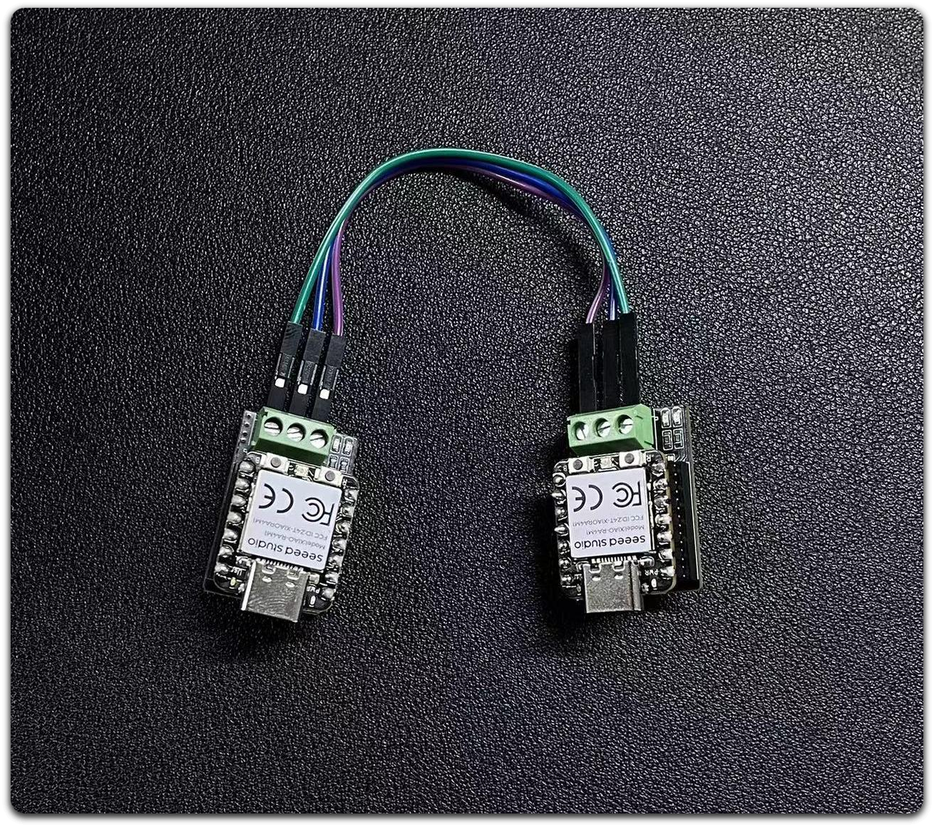
步骤 1. 准备两个 CAN Bus Breakout Board 和 XIAO RA4M1
步骤 2. 将这两个 XIAO RA4M1 分别插入 CAN Bus Breakout Board
步骤 3. 准备杜邦线连接
软件准备
我们提供了一个 适用于 MCP2515 板的 Arduino 库。
该库包含多个示例,包括:
- OBDII-PIDs - 从 OBD-II 接口获取数据
- send - 向 CAN 总线发送一帧
- recv - 从 CAN 总线接收一帧
- set_mask_filter_recv - 通过设置掩码和过滤器,从 CAN 总线接收一帧
软件实现
不允许同时为两个 XIAO RA4M1 上电并下载程序,否则会导致串口下载时报错。下载完一个后,将其拔下,然后给另一个 XIAO RA4M1 上电并下载程序,最后再同时上电以查看串口信息。
CAN 写入代码
/*  send a frame from can bus

    CAN Baudrate,

    #define CAN_5KBPS           1
    #define CAN_10KBPS          2
    #define CAN_20KBPS          3
    #define CAN_25KBPS          4
    #define CAN_31K25BPS        5
    #define CAN_33KBPS          6
    #define CAN_40KBPS          7
    #define CAN_50KBPS          8
    #define CAN_80KBPS          9
    #define CAN_83K3BPS         10
    #define CAN_95KBPS          11
    #define CAN_100KBPS         12
    #define CAN_125KBPS         13
    #define CAN_200KBPS         14
    #define CAN_250KBPS         15
    #define CAN_500KBPS         16
    #define CAN_666KBPS         17
    #define CAN_1000KBPS        18
*/

#include <mcp_can.h>
#include <SPI.h>

/* Please modify SPI_CS_PIN to adapt to your board.

   CANBed V1        - 17
   CANBed M0        - 3
   CAN Bus Shield   - 9
   CANBed 2040      - 9
   CANBed Dual      - 9
   OBD-2G Dev Kit   - 9
   OBD-II GPS Kit   - 9
   Hud Dev Kit      - 9

   Seeed Studio CAN-Bus Breakout Board for XIAO and QT Py - D7
*/

#define SPI_CS_PIN  D7

MCP_CAN CAN(SPI_CS_PIN);                                    // Set CS pin

void setup()
{
    Serial.begin(115200);
    while(!Serial);

    // below code need for OBD-II GPS Dev Kit Atemga32U4 version
    // pinMode(A3, OUTPUT);
    // digitalWrite(A3, HIGH);

    // below code need for OBD-II GPS Dev Kit RP2040 version
    // pinMode(12, OUTPUT);
    // digitalWrite(12, HIGH);

    while (CAN_OK != CAN.begin(CAN_500KBPS))    // init can bus : baudrate = 500k
    {
        Serial.println("CAN BUS FAIL!");
        delay(100);
    }
    Serial.println("CAN BUS OK!");
}

unsigned char stmp[8] = {0, 1, 2, 3, 4, 5, 6, 7};
void loop()
{
    CAN.sendMsgBuf(0x00, 0, 8, stmp);
    delay(100);                       // send data per 100ms
}

// END FILE
CAN 读取代码
/*  receive a frame from can bus

    CAN Baudrate,

    #define CAN_5KBPS           1
    #define CAN_10KBPS          2
    #define CAN_20KBPS          3
    #define CAN_25KBPS          4
    #define CAN_31K25BPS        5
    #define CAN_33KBPS          6
    #define CAN_40KBPS          7
    #define CAN_50KBPS          8
    #define CAN_80KBPS          9
    #define CAN_83K3BPS         10
    #define CAN_95KBPS          11
    #define CAN_100KBPS         12
    #define CAN_125KBPS         13
    #define CAN_200KBPS         14
    #define CAN_250KBPS         15
    #define CAN_500KBPS         16
    #define CAN_666KBPS         17
    #define CAN_1000KBPS        18

    CANBed V1: https://www.longan-labs.cc/1030008.html
    CANBed M0: https://www.longan-labs.cc/1030014.html
    CAN Bus Shield: https://www.longan-labs.cc/1030016.html
    OBD-II CAN Bus GPS Dev Kit: https://www.longan-labs.cc/1030003.html
*/

#include <SPI.h>
#include "mcp_can.h"

/* Please modify SPI_CS_PIN to adapt to your board.

   CANBed V1        - 17
   CANBed M0        - 3
   CAN Bus Shield   - 9
   CANBed 2040      - 9
   CANBed Dual      - 9
   OBD-2G Dev Kit   - 9
   OBD-II GPS Kit   - 9
   Hud Dev Kit      - 9

   Seeed Studio CAN-Bus Breakout Board for XIAO and QT Py - D7
*/


#define SPI_CS_PIN  D7

MCP_CAN CAN(SPI_CS_PIN);                                    // Set CS pin


void setup()
{
    Serial.begin(115200);
    while(!Serial);

    // below code need for OBD-II GPS Dev Kit Atemga32U4 version
    // pinMode(A3, OUTPUT);
    // digitalWrite(A3, HIGH);

    // below code need for OBD-II GPS Dev Kit RP2040 version
    // pinMode(12, OUTPUT);
    // digitalWrite(12, HIGH);

    while (CAN_OK != CAN.begin(CAN_500KBPS))    // init can bus : baudrate = 500k
    {
        Serial.println("CAN BUS FAIL!");
        delay(100);
    }
    Serial.println("CAN BUS OK!");
}


void loop()
{
    unsigned char len = 0;
    unsigned char buf[8];

    if(CAN_MSGAVAIL == CAN.checkReceive())            // check if data coming
    {
        CAN.readMsgBuf(&len, buf);    // read data,  len: data length, buf: data buf

        unsigned long canId = CAN.getCanId();

        Serial.println("-----------------------------");
        Serial.print("Get data from ID: ");
        Serial.println(canId, HEX);

        for(int i = 0; i<len; i++)    // print the data
        {
            Serial.print(buf[i], HEX);
            Serial.print("\t");
        }
        Serial.println();
    }
}

// END FILE
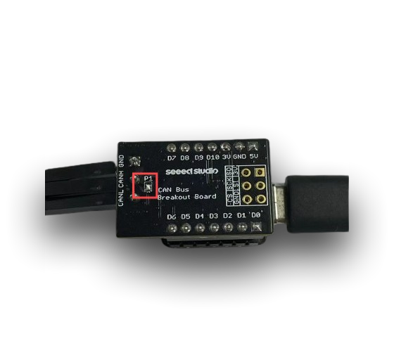
在本示例中,你需要焊接 CAN Bus Breakout Board 端子引脚 P1 中的一个引脚,只有这样才能使用任意速率,否则你只能使用低于 125 的 CAN 波特率
CAN(其他收发器)
我们要感谢 Arduino 提供的教程和代码。
硬件准备
CAN 协议要求发送端必须接收到自己发送的报文。仅仅连接 TX 和 RX 并不足以完成通信;必须连接一个收发器才能进行通信。这里我们使用官方 Arduino SN65HVD230 分裂器模块。
| 3.3 V | GND | D9(CANRX0) | D10 (CANTX0) |
|---|---|---|---|
| VCC | GND | CANRX | CANTX |
软件准备
CAN 写入代码
/*
  CANWrite

  Write and send CAN Bus messages

  See the full documentation here:
  https://docs.arduino.cc/tutorials/uno-r4-wifi/can
*/

/**************************************************************************************
 * INCLUDE
 **************************************************************************************/

#include <Arduino_CAN.h>

/**************************************************************************************
 * CONSTANTS
 **************************************************************************************/

static uint32_t const CAN_ID = 0x20;

/**************************************************************************************
 * SETUP/LOOP
 **************************************************************************************/

void setup()
{
  Serial.begin(115200);
  while (!Serial) { }

  if (!CAN.begin(CanBitRate::BR_250k))
  {
    Serial.println("CAN.begin(...) failed.");
    for (;;) {}
  }
}

static uint32_t msg_cnt = 0;

void loop()
{
  /* Assemble a CAN message with the format of
   * 0xCA 0xFE 0x00 0x00 [4 byte message counter]
   */
  uint8_t const msg_data[] = {0xCA,0xFE,0,0,0,0,0,0};
  memcpy((void *)(msg_data + 4), &msg_cnt, sizeof(msg_cnt));
  CanMsg const msg(CanStandardId(CAN_ID), sizeof(msg_data), msg_data);

  /* Transmit the CAN message, capture and display an
   * error core in case of failure.
   */
  if (int const rc = CAN.write(msg); rc < 0)
  {
    Serial.print  ("CAN.write(...) failed with error code ");
    Serial.println(rc);
    for (;;) { }
  }

  /* Increase the message counter. */
  msg_cnt++;

  /* Only send one message per second. */
  delay(1000);
}
CAN 读取代码
/*
  CANRead

  Receive and read CAN Bus messages

  See the full documentation here:
  https://docs.arduino.cc/tutorials/uno-r4-wifi/can
*/

/**************************************************************************************
 * INCLUDE
 **************************************************************************************/

#include <Arduino_CAN.h>

/**************************************************************************************
 * SETUP/LOOP
 **************************************************************************************/

void setup()
{
  Serial.begin(115200);
  while (!Serial) { }

  if (!CAN.begin(CanBitRate::BR_250k))
  {
    Serial.println("CAN.begin(...) failed.");
    for (;;) {}
  }
}

void loop()
{
  if (CAN.available())
  {
    CanMsg const msg = CAN.read();
    Serial.println(msg);
  }
}
什么时候需要连接终端电阻?
-
- 远距离通信:如果 CAN 总线较长(例如超过 1 米),则必须在总线两端连接终端电阻,以避免信号反射导致的通信问题。
-
- 多节点通信:如果多个节点连接到同一条 CAN 总线上,终端电阻同样必不可少。它们可以确保总线阻抗的稳定,从而防止信号失真。
什么时候可以断开终端电阻?
-
- 短距离通信:在某些短距离应用中(通常小于 1 米),可以省略终端电阻,因为信号反射对通信的影响相对较小。
-
- 单节点通信:如果总线上只有一个节点(例如在调试环境中)且距离较短,则可以暂时断开终端电阻。
| 发送端代码结果 | 接收端代码结果 |
|---|---|
 |  |
技术支持与产品讨论
感谢你选择我们的产品!我们将为你提供多种支持,以确保你在使用我们产品的过程中尽可能顺利。我们提供多种沟通渠道,以满足不同的偏好和需求。