XIAO STM32C5 CANFD 使用
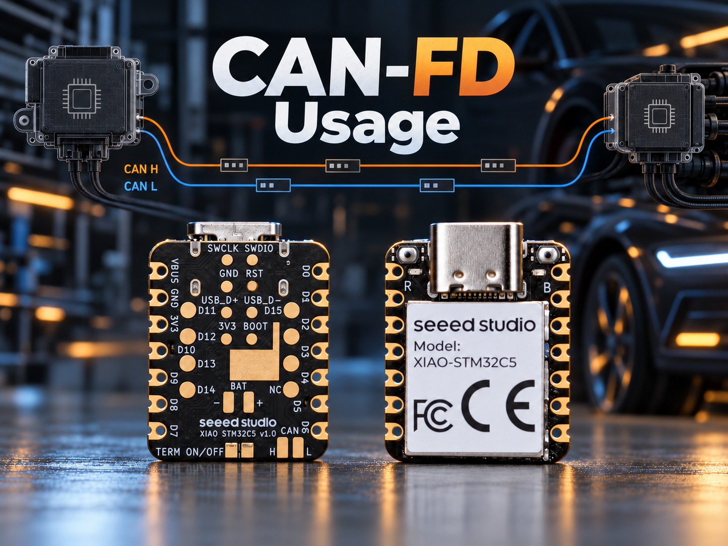
CAN 总线简介
CAN(控制器局域网,Controller Area Network)是一种由 Bosch 自 1983 年开始开发并于 1986 年公开推出的串行通信总线。它最初是为汽车电子设计的,现在已广泛应用于工业自动化、机器人、医疗设备和嵌入式系统。
CAN 的数据链路层和高速物理层由 ISO 11898 系列标准定义。从 OSI 模型的角度来看,CAN 主要规定了以下两层:
- 物理层:定义布线、电气信号、比特定时以及收发器连接。
- 数据链路层:定义帧格式、总线仲裁、错误检测和故障隔离。
CAN 的主要特性包括:
- 多主通信:当总线空闲时,任何节点都可以尝试发送,而无需依赖专用主站轮询。
- 基于报文的广播:帧携带的是报文标识符,而不是源地址和目的地址。每个节点通过滤波器来决定接收哪些报文。
- 无破坏性仲裁:当多个节点同时发送时,从最高有效位开始逐位比较标识符。在第一个不同的位上,占优的
0会覆盖隐性的1,使得数值上更小的标识符具有更高优先级。失去仲裁的节点会停止发送,而不会破坏获胜帧。 - 健壮的错误处理:CAN 控制器可以检测位错误、填充错误、CRC 错误、格式错误和 ACK 错误。错误计数器和自动重发机制提高了通信可靠性。
- 布线和器件成本低:高速 CAN 通常只需要一对双绞线、每个节点一个收发器,以及总线两端各一个终端电阻。
CAN 物理信号
高速 CAN 通常使用由 CAN_H 和 CAN_L 组成的一对双绞线。接收端通过两条信号线之间的差分电压来判断总线状态:
V_diff = V(CAN_H) - V(CAN_L)
- 隐性位
1:CAN_H 和 CAN_L 处于相近的电压水平,产生接近 0 V 的差分电压。对于常见的 5 V 高速 CAN 收发器,两条线通常都接近 2.5 V。 - 显性位
0:CAN_H 电压升高,而 CAN_L 电压降低。对于常见的 5 V 高速 CAN 收发器,典型电平分别约为 3.5 V 和 1.5 V,产生约 2 V 的差分电压。
这些是典型电压值。实际数值取决于收发器、供电电压、总线负载以及共模电压。请参考收发器数据手册中的规定工作范围。
在 CAN 总线上,显性 0 优先于隐性 1。这一特性实现了无破坏性的逐位仲裁,并允许接收节点在 ACK 时隙发送显性位以确认正确接收帧。
经典 CAN 数据帧
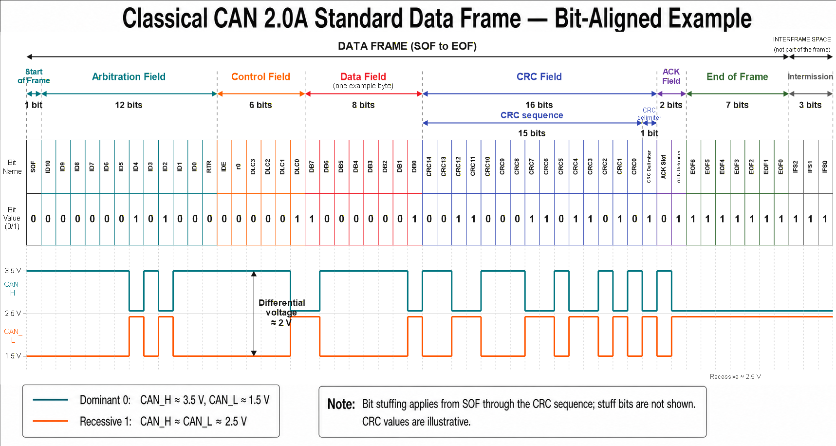
下面以一个经典 CAN 2.0A 数据帧为例:标识符 0x00A,DLC 为 1,数据为 0x81,CRC-15/CAN 为 0x18DA。字段标签、逻辑位以及 CAN_H/CAN_L 波形按列对齐。
- 数据帧字段
| 字段 | 长度 | 描述 |
|---|---|---|
| SOF | 1 bit | 一个显性 0 标记帧的开始并对节点进行同步。 |
| Identifier | 11 bits | 标识报文并决定其仲裁优先级。 |
| RTR | 1 bit | 数据帧为显性 0;远程帧为隐性 1。 |
| IDE | 1 bit | 标准帧为显性 0;扩展帧为隐性 1。 |
| r0 | 1 bit | 作为显性 0 发送的保留位。 |
| DLC | 4 bits | 取值从 0 到 8 时,指定 0 到 8 字节的有效载荷长度。在经典 CAN 中,取值 9 到 15 也表示 8 字节有效载荷。 |
| Data | 0–8 bytes | 包含由 DLC 指定的有效载荷。 |
| CRC sequence | 15 bits | 使接收节点能够检测传输错误。 |
| CRC delimiter | 1 bit | 固定为隐性 1。 |
| ACK slot | 1 bit | 发送端发送隐性 1;无错误接收该帧的节点会用显性 0 覆盖它。 |
| ACK delimiter | 1 bit | 固定为隐性 1。 |
| EOF | 7 bits | 七个连续的隐性位标记帧结束。 |
| Intermission | 3 bits | 帧之后的三个隐性位;属于帧间隔的一部分,而不是帧本身。 |
CAN 帧是如何发送的
- 在检测到总线空闲后,发送节点以 SOF 位开始发送帧。
- 如果多个节点同时开始发送,它们会在仲裁字段期间逐位比较总线状态。发送隐性
1却检测到显性0的节点会失去仲裁并停止发送。 - 获胜节点继续发送控制字段和数据字段。接收节点根据标识符对帧进行滤波,并根据 DLC 确定有效载荷长度。
- 接收节点移除填充位并校验 CRC。如果帧格式和 CRC 有效,它们会在 ACK 时隙发送显性
0。 - 发送节点在检测到 ACK 后完成发送。如果未检测到 ACK,它会报告 ACK 错误,并通常根据控制器配置尝试重发。
比特填充
从 SOF 到 CRC 序列结束,发送端在连续五个相同逻辑值的比特之后插入一个互补的填充位。接收端会自动移除这些填充位。
比特填充为同步提供信号边沿,并有助于错误检测。填充位不属于任何帧字段,也不计入 DLC 或各字段规定的长度。因此,实际传输时间取决于比特率、有效载荷长度以及插入的填充位数量。
CAN FD 简介
经典 CAN 支持的最大有效载荷为 8 字节,标称比特率最高为 1 Mbit/s。为支持更大数据量的传输,Bosch 于 2012 年推出了 CAN FD(具有灵活数据速率的 CAN,CAN with Flexible Data-rate)。
其主要改进包括:
- 将每帧的最大有效载荷从 8 字节 提升到 64 字节。
- 使用 BRS 位在数据阶段切换到更高比特率,并在 ACK 字段之前恢复到标称比特率。
- 根据有效载荷长度使用 17 位或 21 位 CRC 序列,并引入新的 DLC 与有效载荷长度映射关系。
- 在仲裁阶段保留经典 CAN 的报文标识符和逐位仲裁机制。
可实现的 CAN FD 数据阶段比特率取决于控制器、收发器、时钟精度、电缆长度、节点数量以及网络拓扑。常见的数据阶段比特率包括 2 Mbit/s、5 Mbit/s 及更高。
在 PlatformIO 中使用 CAN FD
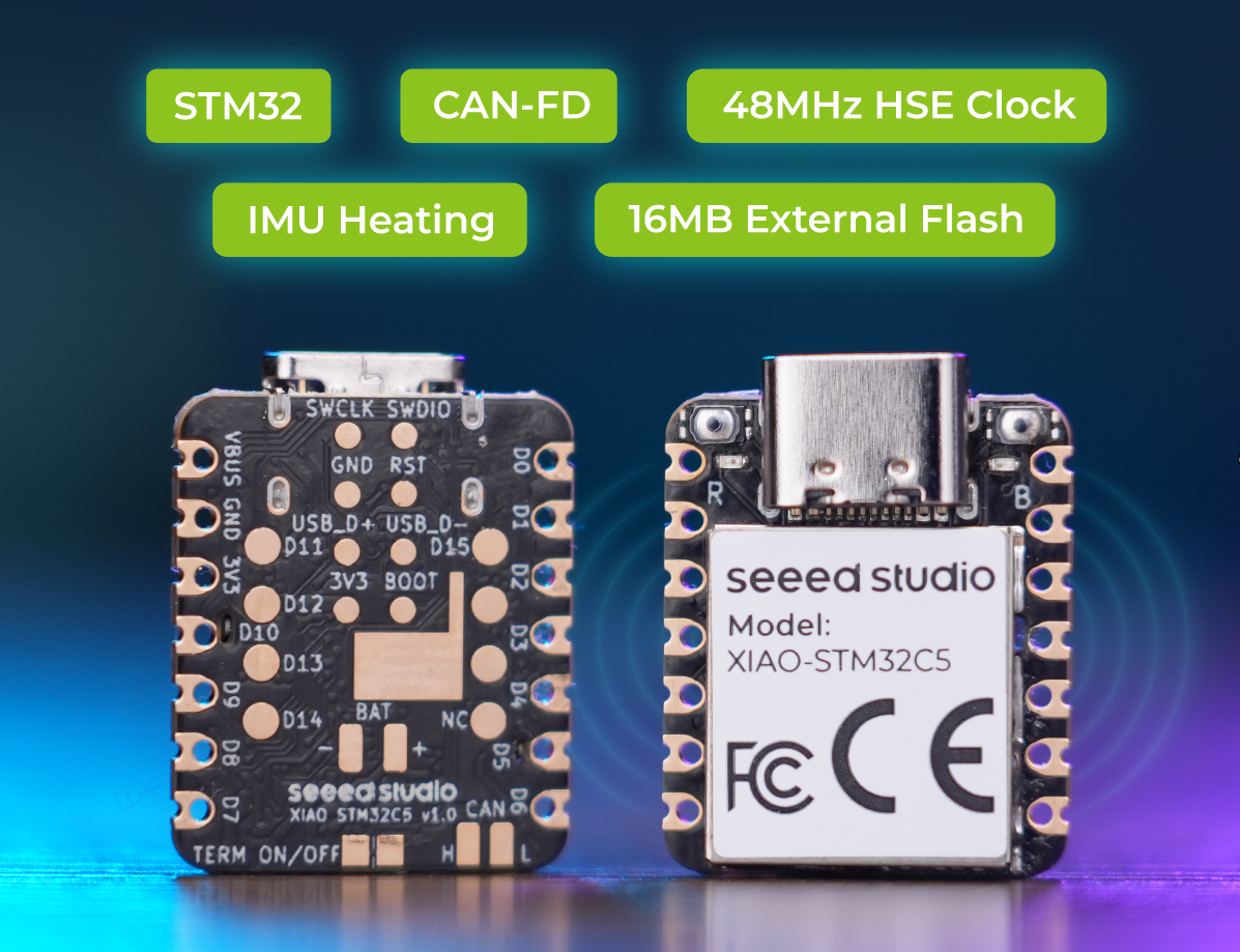
XIAO STM32C5 提供了带板载收发器和终端电阻的 CAN FD 接口,可通过 CAN_H 和 CAN_L 直接连接总线。
本示例使用 PlatformIO 和 Zephyr 框架,配合两块 XIAO STM32C5 开发板:
- 开发板 A 发送 CAN FD 帧。
- 开发板 B 接收并处理这些帧,然后根据接收到的数据控制其板载用户 LED。
本示例使用 PlatformIO。如果你还不熟悉它,请参阅 XIAO STM32C5 的 PlatformIO 入门。
- 查看 CAN 外设的硬件引脚资源。
XIAO STM32C5 提供两个 CAN FD 接口。其中一个引出逻辑电平的 TX 和 RX 信号,用于连接外部 CAN 收发器。另一个连接到板载的 TCAN3403-Q1 CAN FD 收发器,并通过 CAN_H 和 CAN_L 提供直接的总线访问。
板载 CAN FD 电路包含一个可断开的 120 Ω 终端电阻。当开发板位于总线任一端时,应启用该电阻;当开发板处于中间节点,或在 XIAO 端已经安装了另一个 120 Ω 电阻时,应断开该电阻。收发器还支持待机模式,在不需要 CAN 通信时可降低功耗。
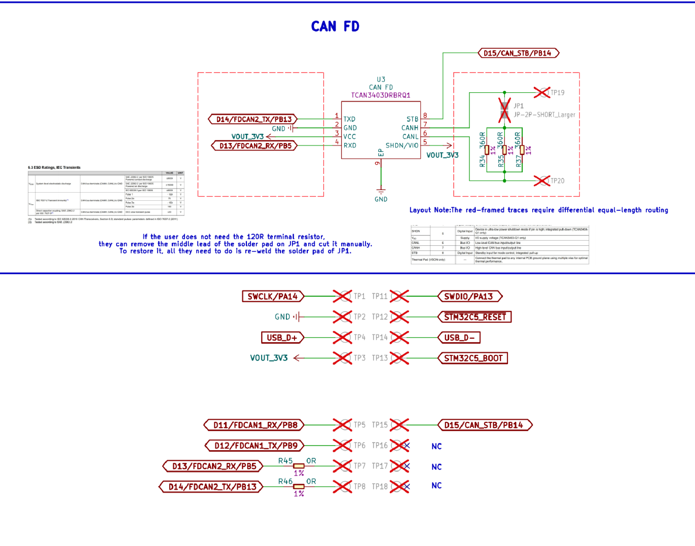
背面的 CAN_H 和 CAN_L 焊盘可以直接使用。但如果使用圆形焊盘,则需要配套独立的 CAN 转换芯片和匹配的终端电阻。
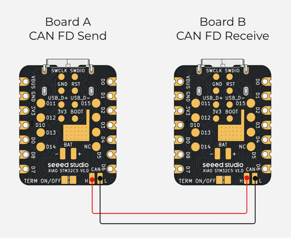
- 修改
app.overlaydevicetree 文件。在 XIAO STM32C5 上,使用的是canfd2节点。CAN 收发引脚为 FDCAN2_RX‑PB5 和 FDCAN2_TX‑PB13,带有 CAN_STB‑PB14。对应的 devicetree 别名节点为fdcan2_rx_pb5、fdcan2_tx_pb13和can_phy0。
/* FDCAN2, transceiver standby, and USB CDC are configured by the board DTS. */
- 修改配置文件,并为
fdcan2添加相关配置。
# CAN FD: 500 kbit/s arbitration and 2 Mbit/s data phases.
CONFIG_CAN=y
CONFIG_CAN_FD_MODE=y
CONFIG_CAN_DEFAULT_BITRATE=500000
CONFIG_CAN_DEFAULT_BITRATE_DATA=2000000

# Keep application status output enabled; the board routes it to USB CDC.
CONFIG_PRINTK=y
- 编写
main.c程序。本示例使用两块 XIAO STM32C5 开发板。开发板 A 作为发送端,用于发送 CAN 协议数据;开发板 B 作为接收端,用于接收并解析 CAN 报文,然后点亮板载 LED。
CANFD 发送程序
/*
 * XIAO STM32C5 CAN FD sender (board A)
 *
 * Sends one 16-byte CAN FD frame with standard ID 0x123 over FDCAN2
 * every second. BRS uses 500 kbit/s for arbitration and 2 Mbit/s for
 * the data phase. Transmission status is printed through USB CDC ACM.
 */
#include <zephyr/device.h>
#include <zephyr/devicetree.h>
#include <zephyr/drivers/can.h>
#include <zephyr/kernel.h>

#include <stdint.h>

#define CAN_NODE DT_CHOSEN(zephyr_canbus)
#define CAN_ID 0x123U
#define CAN_DATA_LENGTH 16U
#define CAN_DATA_DLC 10U
#define SEND_PERIOD_MS 1000

static const struct device *const can_dev = DEVICE_DT_GET(CAN_NODE);

/* Encode multibyte fields explicitly as little-endian wire data. */
static void put_u16_le(uint8_t *dst, uint16_t value)
{
 dst[0] = (uint8_t)value;
 dst[1] = (uint8_t)(value >> 8);
}

static void put_u32_le(uint8_t *dst, uint32_t value)
{
 dst[0] = (uint8_t)value;
 dst[1] = (uint8_t)(value >> 8);
 dst[2] = (uint8_t)(value >> 16);
 dst[3] = (uint8_t)(value >> 24);
}

static uint8_t payload_checksum(const uint8_t *data)
{
 uint8_t checksum = 0U;

 for (size_t i = 0U; i < CAN_DATA_LENGTH - 1U; i++) {
  checksum ^= data[i];
 }

 return checksum;
}

/*
 * 16-byte application payload:
 *   [0..3]   sequence number (uint32, little-endian)
 *   [4..7]   sender uptime in milliseconds (uint32, little-endian)
 *   [8..9]   example measurement A (int16, little-endian)
 *   [10..11] example measurement B (int16, little-endian)
 *   [12]     state value cycling from 0 to 3
 *   [13..14] fixed markers 0x5A and 0xA5
 *   [15]     XOR checksum of bytes 0 through 14
 */
static void build_frame(struct can_frame *frame, uint32_t sequence)
{
 int16_t measurement_a = (int16_t)(250 + (sequence % 50U));
 int16_t measurement_b = (int16_t)(-100 + (sequence % 20U));

 *frame = (struct can_frame) {
  .id = CAN_ID,
  .dlc = CAN_DATA_DLC,
  /* FDF selects CAN FD; BRS enables the faster data phase. */
  .flags = CAN_FRAME_FDF | CAN_FRAME_BRS,
 };

 put_u32_le(&frame->data[0], sequence);
 put_u32_le(&frame->data[4], k_uptime_get_32());
 put_u16_le(&frame->data[8], (uint16_t)measurement_a);
 put_u16_le(&frame->data[10], (uint16_t)measurement_b);
 frame->data[12] = (uint8_t)(sequence & 0x03U);
 frame->data[13] = 0x5AU;
 frame->data[14] = 0xA5U;
 frame->data[15] = payload_checksum(frame->data);
}

int main(void)
{
 uint32_t sequence = 0U;
 int ret;

 if (!device_is_ready(can_dev)) {
  printk("FDCAN2 device is not ready\r\n");
  return 0;
 }

 /* The controller mode must be selected before the controller starts. */
 ret = can_set_mode(can_dev, CAN_MODE_FD);
 if (ret != 0) {
  printk("Failed to enable CAN FD mode: %d\r\n", ret);
  return 0;
 }

 ret = can_start(can_dev);
 if (ret != 0) {
  printk("Failed to start FDCAN2: %d\r\n", ret);
  return 0;
 }

 printk("FDCAN2 sender started: ID=0x%03x, 500 kbit/s + 2 Mbit/s data\r\n",
        CAN_ID);

 while (true) {
  struct can_frame frame;

  build_frame(&frame, sequence);
  /* A NULL callback makes this synchronous, with a 100 ms timeout. */
  ret = can_send(can_dev, &frame, K_MSEC(100), NULL, NULL);
  if (ret == 0) {
   printk("TX sequence=%u time=%u ms state=%u\r\n",
          sequence, k_uptime_get_32(), frame.data[12]);
   sequence++;
  } else {
   printk("FDCAN2 send failed: %d\r\n", ret);
  }

  k_msleep(SEND_PERIOD_MS);
 }

 return 0;
}
CAN 接收程序
/*
 * XIAO STM32C5 CAN FD receiver (board B)
 *
 * FDCAN2 accepts standard ID 0x123, decodes the 16-byte application
 * payload, and prints it through USB CDC ACM. A valid frame lights the
 * onboard LED for 100 ms. With no traffic, the LED stays off and a
 * timeout warning is printed once per second.
 */
#include <zephyr/device.h>
#include <zephyr/devicetree.h>
#include <zephyr/drivers/can.h>
#include <zephyr/drivers/gpio.h>
#include <zephyr/kernel.h>

#include <stdint.h>

#define CAN_NODE DT_CHOSEN(zephyr_canbus)
#define CAN_ID 0x123U
#define CAN_DATA_LENGTH 16U
#define CAN_DATA_DLC 10U
#define LED_FLASH_MS 100
#define RX_POLL_MS 20
#define NO_RX_REPORT_MS 1000

static const struct device *const can_dev = DEVICE_DT_GET(CAN_NODE);
static const struct gpio_dt_spec led =
 GPIO_DT_SPEC_GET(DT_ALIAS(led0), gpios);

/* The driver posts frames from interrupt context; the main loop consumes them. */
CAN_MSGQ_DEFINE(rx_msgq, 10);

/* Decode multibyte fields using the sender's little-endian wire format. */
static uint16_t get_u16_le(const uint8_t *src)
{
 return (uint16_t)src[0] | ((uint16_t)src[1] << 8);
}

static uint32_t get_u32_le(const uint8_t *src)
{
 return (uint32_t)src[0] |
        ((uint32_t)src[1] << 8) |
        ((uint32_t)src[2] << 16) |
        ((uint32_t)src[3] << 24);
}

static uint8_t payload_checksum(const uint8_t *data)
{
 uint8_t checksum = 0U;

 for (size_t i = 0U; i < CAN_DATA_LENGTH - 1U; i++) {
  checksum ^= data[i];
 }

 return checksum;
}

/*
 * Print the raw payload and its decoded fields.
 * A true return value means the XOR checksum passed and permits an LED flash.
 */
static bool print_frame(const struct can_frame *frame)
{
 uint32_t sequence = get_u32_le(&frame->data[0]);
 uint32_t tx_time_ms = get_u32_le(&frame->data[4]);
 int16_t measurement_a = (int16_t)get_u16_le(&frame->data[8]);
 int16_t measurement_b = (int16_t)get_u16_le(&frame->data[10]);
 uint8_t state = frame->data[12];
 uint8_t received_checksum = frame->data[15];
 uint8_t calculated_checksum = payload_checksum(frame->data);

 printk("RX ID=0x%03x DLC=%u DATA=", frame->id, frame->dlc);
 for (size_t i = 0U; i < CAN_DATA_LENGTH; i++) {
  printk("%02x%s", frame->data[i],
         (i == CAN_DATA_LENGTH - 1U) ? "" : " ");
 }
 printk("\r\n");

 printk("PARSED sequence=%u tx_time=%u ms measurement_a=%d "
        "measurement_b=%d state=%u checksum=%s\r\n",
        sequence, tx_time_ms, measurement_a, measurement_b, state,
        received_checksum == calculated_checksum ? "OK" : "ERROR");

 return received_checksum == calculated_checksum;
}

int main(void)
{
 /* Match standard 11-bit ID 0x123; other IDs do not enter the queue. */
 const struct can_filter filter = {
  .id = CAN_ID,
  .mask = CAN_STD_ID_MASK,
  .flags = 0U,
 };
 int64_t led_off_time = 0;
 int64_t last_rx_time = k_uptime_get();
 int64_t last_no_rx_report_time = last_rx_time;
 int filter_id;
 int ret;

 if (!gpio_is_ready_dt(&led)) {
  printk("LED device is not ready\r\n");
  return 0;
 }

 /* GPIO_OUTPUT_INACTIVE honors devicetree polarity and starts with LED off. */
 ret = gpio_pin_configure_dt(&led, GPIO_OUTPUT_INACTIVE);
 if (ret != 0) {
  printk("Failed to configure LED: %d\r\n", ret);
  return 0;
 }

 if (!device_is_ready(can_dev)) {
  printk("FDCAN2 device is not ready\r\n");
  return 0;
 }

 /* Enable CAN FD mode before starting the controller. */
 ret = can_set_mode(can_dev, CAN_MODE_FD);
 if (ret != 0) {
  printk("Failed to enable CAN FD mode: %d\r\n", ret);
  return 0;
 }

 /* Queue matching frames so parsing and printing stay out of interrupt context. */
 filter_id = can_add_rx_filter_msgq(can_dev, &rx_msgq, &filter);
 if (filter_id < 0) {
  printk("Failed to add receive filter: %d\r\n", filter_id);
  return 0;
 }

 ret = can_start(can_dev);
 if (ret != 0) {
  printk("Failed to start FDCAN2: %d\r\n", ret);
  return 0;
 }

 printk("FDCAN2 receiver started: ID=0x%03x, output via USB CDC\r\n",
        CAN_ID);

 while (true) {
  struct can_frame frame;

  /*
   * Poll with a short timeout instead of blocking forever so the loop
   * can turn off the LED and report an absence of CAN traffic.
   */
  if (k_msgq_get(&rx_msgq, &frame, K_MSEC(RX_POLL_MS)) != 0) {
   int64_t now = k_uptime_get();

   if (led_off_time != 0 && now >= led_off_time) {
    (void)gpio_pin_set_dt(&led, 0);
    led_off_time = 0;
   }

   if ((now - last_rx_time) >= NO_RX_REPORT_MS &&
       (now - last_no_rx_report_time) >= NO_RX_REPORT_MS) {
    printk("WARN: no FDCAN2 data received for %lld ms\r\n",
           now - last_rx_time);
    last_no_rx_report_time = now;
   }
   continue;
  }

  last_rx_time = k_uptime_get();
  last_no_rx_report_time = last_rx_time;

  /* This example only decodes 16-byte CAN FD frames. */
  if ((frame.flags & CAN_FRAME_FDF) == 0U ||
      frame.dlc != CAN_DATA_DLC) {
   printk("Ignored non-matching frame: flags=0x%x dlc=%u\r\n",
          frame.flags, frame.dlc);
   (void)gpio_pin_set_dt(&led, 0);
   led_off_time = 0;
   continue;
  }

  if (print_frame(&frame)) {
   /* Logical GPIO levels automatically handle the active-low onboard LED. */
   (void)gpio_pin_set_dt(&led, 1);
   led_off_time = k_uptime_get() + LED_FLASH_MS;
  } else {
   (void)gpio_pin_set_dt(&led, 0);
   led_off_time = 0;
  }
 }

 return 0;
}
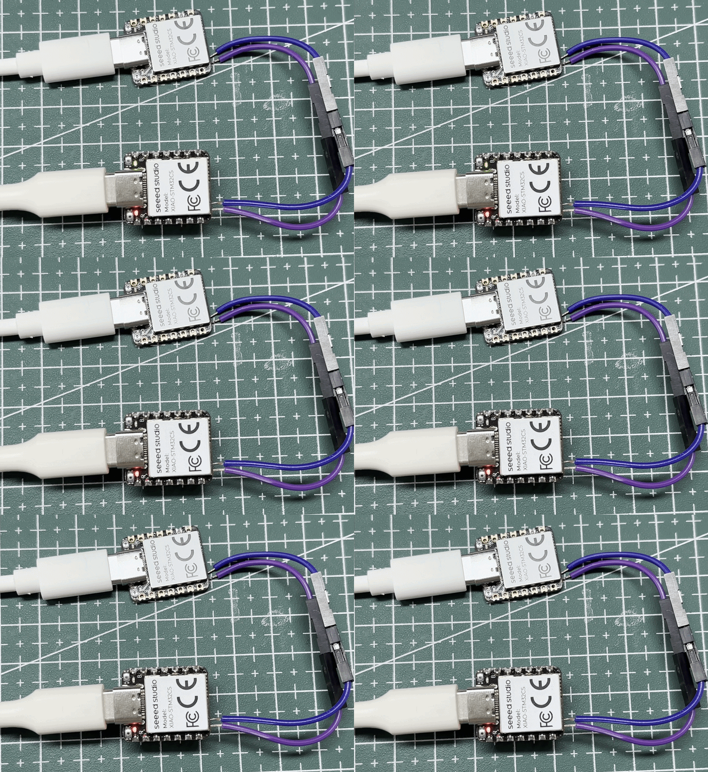
- 结果如下图所示。
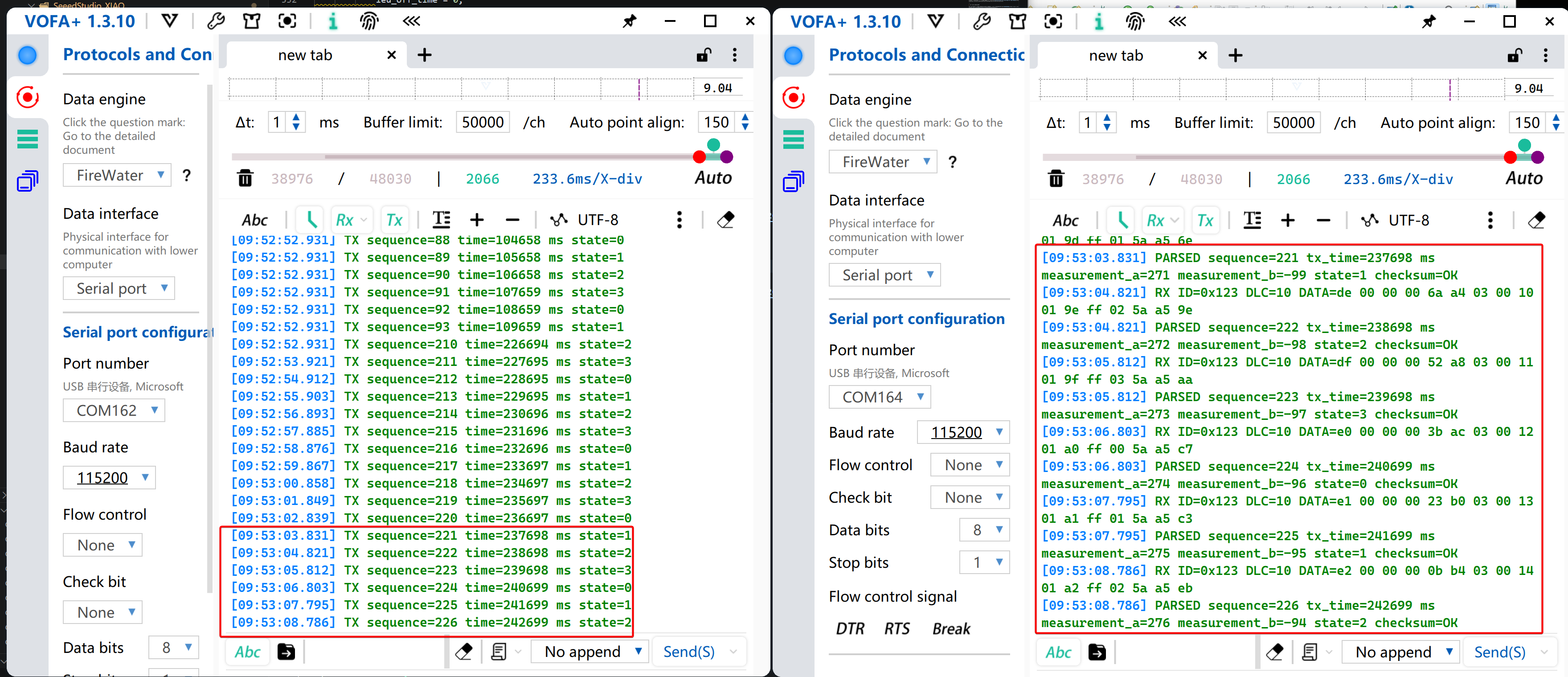
- 将开发板 A 与 B 之间的 CAN_H 对接 CAN_H、CAN_L 对接 CAN_L。如果它们使用独立电源,还需要将地线相连。开发板 B 在接收并校验帧后会闪烁其 LED。
- 使用串口监视器检查发送和解析的数据。
USB 转 CAN 网桥
CAN 网桥将 XIAO STM32C5 变成一个 USB‑CAN 适配器。它在 PC 与 CAN/CAN‑FD 总线之间双向转发消息,使 PC 能够发送控制命令、监控设备状态并记录总线流量。典型应用包括机器人关节电机调试、汽车 ECU 和车载网络分析、工业伺服和 CAN 传感器的集成测试,以及 BMS 状态监控。以机器人开发为例,PC 可以通过 CAN 网桥向关节电机控制器发送使能、位置和速度命令,同时接收角度、电流、温度和故障信息。
本教程提供两种实现:gs_usb 和 slcan。两者在 CAN 侧提供类似功能;主要区别在于主机与板卡之间的数据传输方式、支持的平台以及 CAN‑FD 能力。
gs_usb 与 slcan 对比
gs_usb 是一种用于 USB‑CAN 适配器的通信协议。开发板通过 USB 将 CAN 消息传输到 PC。在 Linux 上,内核中的 gs_usb 驱动会将其直接注册为 SocketCAN 接口,例如 can0。它提供高吞吐量并支持 CAN‑FD,适用于 Linux 下的高速通信、总线监控、自动化测试和长期调试。
slcan 是一种使用 Lawicel ASCII 命令封装 CAN 消息的通信方式。在本项目中,开发板通过 USB CDC 串口与 PC 通信。该板在 Windows 上显示为 COM 端口,在 Linux 上显示为 /dev/ttyACMx。它可以与 SavvyCAN、python‑can 或 slcand 配合使用。这种方式具有协议简单、访问灵活以及良好跨平台兼容性的特点。
使用 gs_usb
本节使用预编译固件演示功能。源代码可从 platform‑seeedboards 仓库下载。
- 开发板上带有 120 Ω 终端电阻。当其启用且开发板位于总线一端时,该端无需额外电阻。请确保另一端也已终端;对于中间节点,请禁用板载电阻。
- 本节基于 Ubuntu 22.04 LTS Linux 发行版。
- 📄[固件] CAN-Bridge-gsusb 固件
- 源代码请参考 GitHub 链接。
- 双击 XIAO STM32C5 上的 Reset 按钮进入 bootloader 模式。下载并将固件文件复制到
XIAOC5BOOT大容量存储盘。为了测试 CAN‑FD 收发性能,请将固件烧录到两块 XIAO STM32C5 板上进行验证。
连接方式请参考接线图。Using CANFD With PlatformIO
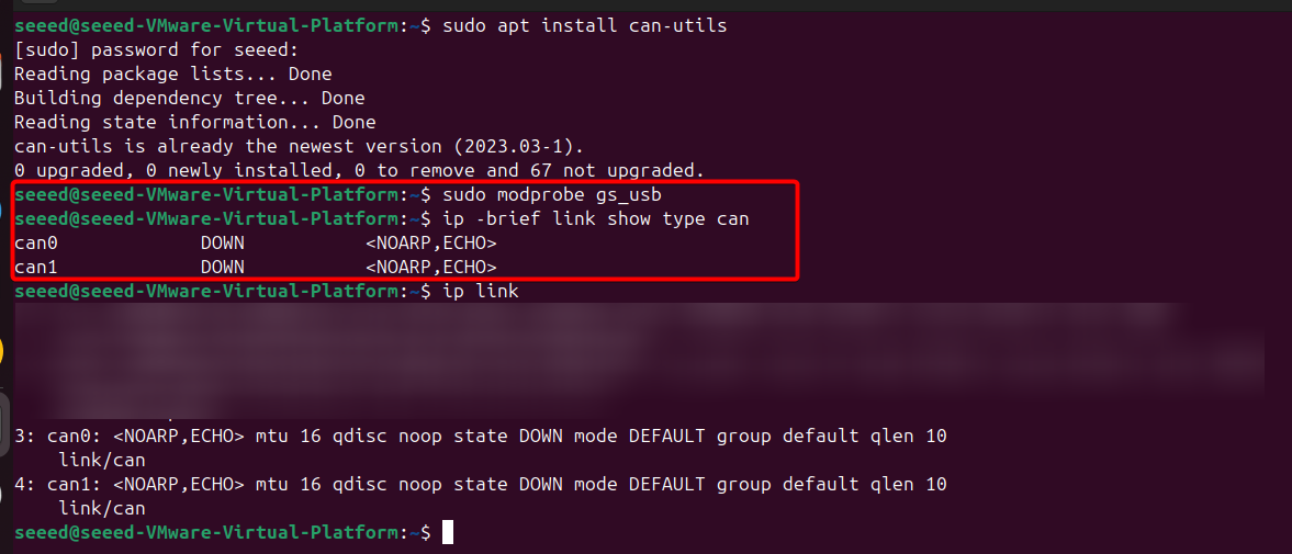
- 将开发板连接到你的 Linux 主机,打开终端并安装所需软件包。随后 CAN 设备会被枚举出来,通常为
can0和can1。
# Install can-utils
sudo apt update
sudo apt install can-utils

# Load gs_usb kernel module
sudo modprobe gs_usb
ip -brief link show type can
- 配置 CAN 接口
# Bring up can0
sudo ip link set can0 down
sudo ip link set can0 type can bitrate 500000 dbitrate 2000000 fd on
sudo ip link set can0 up

# Bring up can1
sudo ip link set can1 down
sudo ip link set can1 type can bitrate 5000000 dbitrate 2000000 fd on
sudo ip link set can1 up
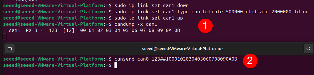
- 发送并监控 CAN‑FD 流量
- 打开另一个终端,在
can1接口上接收数据。
candump -x can1
- 在另一个终端,通过
can0接口发送一个启用 BRS 的 12 字节 CAN‑FD 帧。
cansend can0 123##1000102030405060708090A0B
- 使用脚本进行验证
- 安装
python‑can模块
sudo apt update
sudo apt install python3-can
- 在接收端运行
canfd_2m_test.py
# SPDX-License-Identifier: Apache-2.0
"""Send or receive CAN FD frames at 500 kbit/s nominal and 2 Mbit/s data."""

import argparse
import time

import can

NOMINAL_BITRATE = 500_000
DATA_BITRATE = 2_000_000


def open_bus(interface, channel, serial_number=None, loop_back=False):
    if interface == "socketcan":
        options = {
            "interface": "socketcan",
            "channel": channel,
            "fd": True,
        }
    else:
        try:
            candle_channel = int(channel)
        except ValueError:
            candle_channel = channel
        options = {
            "interface": "candle",
            "channel": candle_channel,
            "fd": True,
            "bitrate": NOMINAL_BITRATE,
            "data_bitrate": DATA_BITRATE,
            "loop_back": loop_back,
            "ignore_config": True,
        }
        if serial_number:
            options["serial_number"] = serial_number
    return can.Bus(**options)


def make_test_frames():
    payload_12 = bytes(range(12))
    payload_64 = bytes(range(64))
    return (
        can.Message(
            arbitration_id=0x200,
            is_extended_id=False,
            is_fd=True,
            bitrate_switch=True,
            data=payload_12,
        ),
        can.Message(
            arbitration_id=0x201,
            is_extended_id=False,
            is_fd=True,
            bitrate_switch=True,
            data=payload_64,
        ),
    )


def send_frames(bus, count, interval):
    frames = make_test_frames()

    acknowledged = 0
    for _ in range(count):
        for frame in frames:
            try:
                bus.send(frame, timeout=1.0)
                acknowledged += 1
                print(
                    f"TX ID={frame.arbitration_id:#05x} len={len(frame.data)} "
                    f"FD={frame.is_fd} BRS={frame.bitrate_switch}"
                )
            except can.CanError as error:
                print(f"TX failed for ID {frame.arbitration_id:#05x}: {error}")
            time.sleep(interval)

    print(f"Transmission complete: {acknowledged} CAN FD frames submitted")


def loopback_test(bus, count, interval):
    frames = make_test_frames()
    passed = 0
    expected = count * len(frames)

    for _ in range(count):
        for frame in frames:
            bus.send(frame, timeout=1.0)
            deadline = time.monotonic() + 1.0
            received = None

            while time.monotonic() < deadline:
                candidate = bus.recv(timeout=0.1)
                if candidate is None:
                    continue
                if (
                    candidate.arbitration_id == frame.arbitration_id
                    and candidate.is_fd
                    and candidate.bitrate_switch
                    and bytes(candidate.data) == bytes(frame.data)
                ):
                    received = candidate
                    break

            if received is None:
                print(
                    f"FAIL ID={frame.arbitration_id:#05x}: "
                    "no matching loopback frame"
                )
            else:
                passed += 1
                print(
                    f"PASS ID={received.arbitration_id:#05x} "
                    f"len={len(received.data)} FD={received.is_fd} "
                    f"BRS={received.bitrate_switch}"
                )
            time.sleep(interval)

    print(f"Loopback complete: {passed}/{expected} CAN FD frames passed")
    if passed != expected:
        raise RuntimeError("CAN FD loopback test failed")


def receive_frames(bus, duration):
    deadline = time.monotonic() + duration
    received = 0
    while time.monotonic() < deadline:
        frame = bus.recv(timeout=0.5)
        if frame is None:
            continue
        received += 1
        print(
            f"RX ID={frame.arbitration_id:#x} len={len(frame.data)} "
            f"FD={frame.is_fd} BRS={frame.bitrate_switch} "
            f"data={bytes(frame.data).hex().upper()}"
        )
    print(f"Reception complete: {received} frames")


def main():
    parser = argparse.ArgumentParser(
        description="XIAO STM32C5 gs_usb CAN FD 500k/2M test"
    )
    parser.add_argument("mode", choices=("send", "receive", "loopback"))
    parser.add_argument(
        "--interface",
        choices=("candle", "socketcan"),
        default="candle",
        help="candle uses direct USB; socketcan uses a Linux canX interface",
    )
    parser.add_argument(
        "--channel",
        default="0",
        help="candle channel number or SocketCAN interface name such as can0",
    )
    parser.add_argument("--serial-number", help="USB serial number for board selection")
    parser.add_argument("--count", type=int, default=10)
    parser.add_argument("--interval", type=float, default=0.1)
    parser.add_argument("--duration", type=float, default=10.0)
    args = parser.parse_args()

    print(
        f"Opening {args.interface} channel {args.channel}: "
        f"nominal={NOMINAL_BITRATE}, "
        f"data={DATA_BITRATE}, FD enabled, "
        f"loopback={args.mode == 'loopback'}"
    )
    bus = open_bus(
        args.interface,
        args.channel,
        args.serial_number,
        loop_back=args.mode == "loopback",
    )
    try:
        if args.mode == "send":
            send_frames(bus, args.count, args.interval)
        elif args.mode == "receive":
            receive_frames(bus, args.duration)
        else:
            loopback_test(bus, args.count, args.interval)
    finally:
        bus.shutdown()


if __name__ == "__main__":
    main()
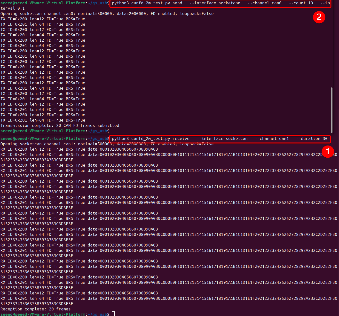
python3 canfd_2m_test.py receive \
  --interface socketcan \
  --channel can1 \
  --duration 30
- 在发送端运行
python3 canfd_2m_test.py send \
  --interface socketcan \
  --channel can0 \
  --count 10 \
  --interval 0.1
使用 slcan 工作
本节演示使用预构建固件的功能。源代码可以从 platform‑seeedboards 仓库下载。
- XIAO STM32C5 已经内置了一个默认启用的 120 Ω CAN 终端电阻,因此你不需要在 CAN_H 和 CAN_L 焊盘之间再焊接额外的电阻。当使用两个 XIAO 板时,每块板上的内置电阻分别终结总线的一端。
- 本节基于 Ubuntu 22.04 LTS Linux 发行版。
- 📄[固件] CAN-Bridge-slcan 固件
- 源代码请参考 GitHub 链接。
- 双击 XIAO STM32C5 上的 Reset 按钮进入 bootloader 模式。下载并将固件文件复制到
XIAOC5BOOT大容量存储驱动器。使用两块已烧录该固件的 XIAO STM32C5 板,或一块 XIAO STM32C5 加另一台支持 slcan 的接收设备。 - 将开发板连接到你的 Linux 主机并打开终端。在
/dev/ttyACM*下找到串口设备,通常为ttyACM0和ttyACM1。
ls /dev/ttyACM*

- 安装 SavvyCAN。下载 V220 或更新版本,然后通过 SavvyCAN 建立连接。
- 对于 Linux 系统,在使用前需要安装
libfuse2软件包。
sudo apt update
sudo apt install libfuse2
- 本示例使用 V220 版本。在 Linux 下按如下方式运行该应用程序:
# For Linux
sudo chmod +x SavvyCAN-7c576c5-x86_64.AppImage
./SavvyCAN-7c576c5-x86_64.AppImage

# On Windows, directly launch the executable SavvyCAN.exe
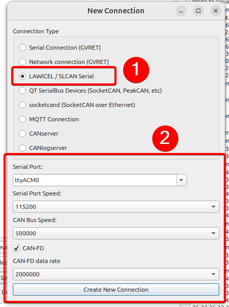
- 进入 Connection → Open Connection Window。点击 Add New Device Connection。将连接类型设置为 LAWICEL / SLCAN Serial。串口选择
ttyACM0。将 Serial Port Speed 设置为115200,CAN Bus Speed 设置为500000 bit/s。启用 CAN‑FD,并将 CAN‑FD data rate 设置为2000000 bit/s。
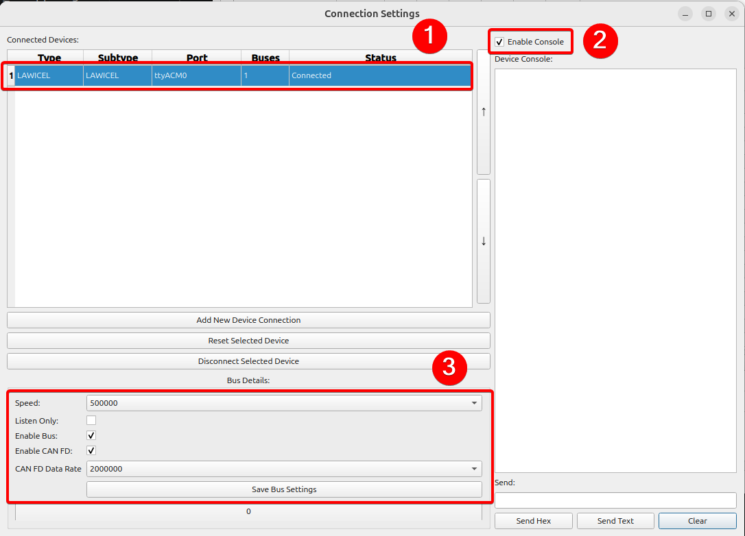
- 配置完成后,连接状态会指示连接是否成功。建议打开右上角的控制台查看日志,确认各参数与设置一致,然后保存配置。
- 打开一个新的终端并运行测试脚本。脚本会自动检测空闲的
/dev/ttyACM*串口设备并发送 CAN‑FD 数据。
python3 savvycan_fd_peer.py send
savvycan_fd_peer.py
# SPDX-License-Identifier: Apache-2.0
"""Send or receive SavvyCAN LAWICEL CAN FD frames with a second XIAO board."""

import argparse
import time

import serial
import serial.tools.list_ports

SEEED_VID = 0x2886
SERIAL_BAUD = 115200


def find_available_port(explicit_port=None):
    candidates = [explicit_port] if explicit_port else [
        port.device
        for port in serial.tools.list_ports.comports()
        if port.vid == SEEED_VID
    ]

    for device in candidates:
        try:
            connection = serial.Serial(device, SERIAL_BAUD, timeout=0.35)
            connection.dtr = True
            connection.rts = False
            time.sleep(0.4)
            connection.reset_input_buffer()
            return connection
        except (OSError, serial.SerialException) as error:
            print(f"Skipping {device}: {error}")

    raise RuntimeError(
        "No available Seeed CDC port. Close SavvyCAN on the peer port or "
        "specify the unused port with --port."
    )


def command(connection, text, response_wait=0.08):
    connection.reset_input_buffer()
    connection.write((text + "\r").encode("ascii"))
    connection.flush()
    time.sleep(response_wait)
    response = connection.read(256)
    if b"\x07" in response:
        raise RuntimeError(f"Firmware rejected command {text!r}: {response!r}")
    if b"\r" not in response:
        raise RuntimeError(f"No acknowledgement for {text!r}: {response!r}")
    return response


def open_can_fd(connection):
    command(connection, "C")
    command(connection, "S6")  # 500 kbit/s nominal bitrate
    command(connection, "Y2")  # 2 Mbit/s CAN FD data bitrate
    command(connection, "O")


def send_frames(connection, duration):
    frames = [
        "d2009000102030405060708090A0B",  # 12-byte standard FD, no BRS
        "b201F" + "".join(f"{value:02X}" for value in range(64)),
        "B001ABCDE9AABBCCDDEEFF001122334455",  # 12-byte extended FD with BRS
    ]
    deadline = time.monotonic() + duration
    sent = 0

    print("Sending IDs 0x200, 0x201, and 0x1ABCDE to SavvyCAN...")
    while time.monotonic() < deadline:
        for frame in frames:
            command(connection, frame, response_wait=0.04)
            sent += 1
            time.sleep(0.16)
    print(f"Transmission complete: {sent} acknowledged CAN FD frames.")


def receive_frames(connection, duration):
    deadline = time.monotonic() + duration
    print("Waiting for CAN FD frames sent by SavvyCAN...")
    connection.reset_input_buffer()
    while time.monotonic() < deadline:
        line = connection.read_until(b"\r")
        if line:
            print(line.decode("ascii", errors="replace").strip())


def main():
    parser = argparse.ArgumentParser()
    parser.add_argument("mode", choices=("send", "receive"))
    parser.add_argument(
        "--port",
        help="Unused peer port, for example COM4 or /dev/ttyACM1",
    )
    parser.add_argument("--duration", type=float, default=12.0)
    args = parser.parse_args()

    connection = find_available_port(args.port)
    print(f"Using {connection.port} at {SERIAL_BAUD} baud")
    try:
        open_can_fd(connection)
        if args.mode == "send":
            send_frames(connection, args.duration)
        else:
            receive_frames(connection, args.duration)
        command(connection, "C")
    finally:
        connection.close()


if __name__ == "__main__":
    main()
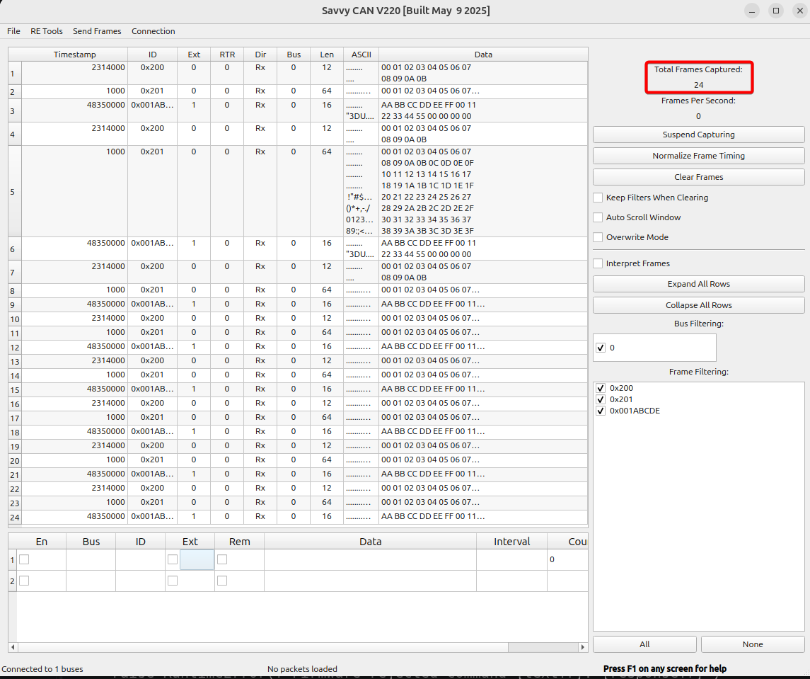
你可以观察到脚本向 /dev/ttyACM1 设备写入了 24 帧 CAN‑FD 帧。/dev/ttyACM0 显示为 busy,因为它被 SavvyCAN 占用。

- 你可以在 SavvyCAN 的主面板上查看接收并解析后的 CAN‑FD 帧数据。
通过 CAN 驱动电机
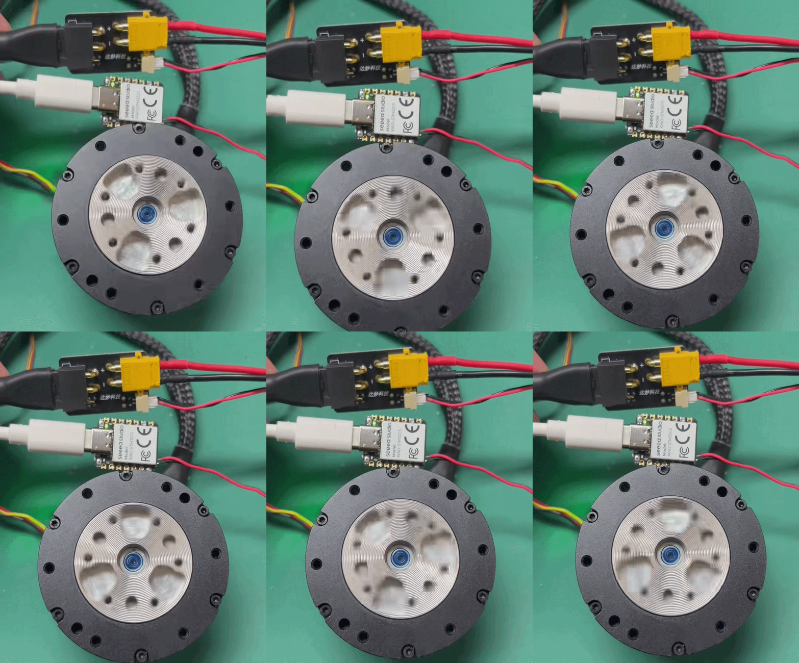
XIAO STM32C5 可以作为高精度无刷电机的 CAN 通信驱动主板。它适用于机器人控制、工业控制以及多电机控制等实际应用场景。
下面的示例通过控制 DM4310 电机来演示其驱动能力。
此示例基于 PlatformIO 构建。如果你是 PlatformIO 新手,请参考 Getting Started with PlatformIO For XIAO STM32C5
硬件准备
- 1 × XIAO STM32C5
- 带 Type‑C 线缆的电脑
- 24 V 电源
- XT30 2+2 供电分离板
- DM4310 电机


软件程序
电机驱动需要 24 V 电源。请使用符合规范的电源,以避免对设备和人身安全造成危害!
-
获取电机 ID。使用 Damiao 上位机软件进行配置:电机 CAN ID:
0x007,主机 ID:0x017。请参考 Damiao 43 Series Motors Getting Started -
通过 PlatformIO 烧录程序,或烧录预编译测试固件:
- 📄[Firmware] CAN-Driver-DM4310 Firmware
- 源代码请参考 GitHub 链接。
- 电机使能后,DM‑J4310 每 5 秒在目标速度
0 → 3 → 6 → 10 → 6 → 3 rad/s之间循环切换。当目标速度非零时,板载 LED 点亮;为零时熄灭。同时通过串口打印电机反馈数据。
- 在驱动电机时,请确保 XIAO STM32C5 上的 CAN_H 和 CAN_L 与所连接设备的 CAN_H 和 CAN_L 正确对应。接线不匹配会导致通信失败。
总结
通过以上示例,你现在应该对如何在 XIAO STM32C5 上使用 CAN‑FD 功能有了基本了解。通过 CAN 传输的有效载荷会根据不同的使用场景和功能需求而变化。CAN 和 CAN‑FD 已被广泛应用于工业控制、具身智能、机器人控制、汽车电子等诸多领域。尽情使用这一特性构建有趣的项目,并在开源社区分享你的作品,让他人发现、学习和复用!
参考来源
技术支持与产品讨论
感谢你选择我们的产品!我们将通过多种支持方式,尽力确保你在使用我们产品时拥有尽可能顺畅的体验。我们提供多种沟通渠道,以满足不同偏好和需求。