使用 XIAO STM32C5 进行引脚复用
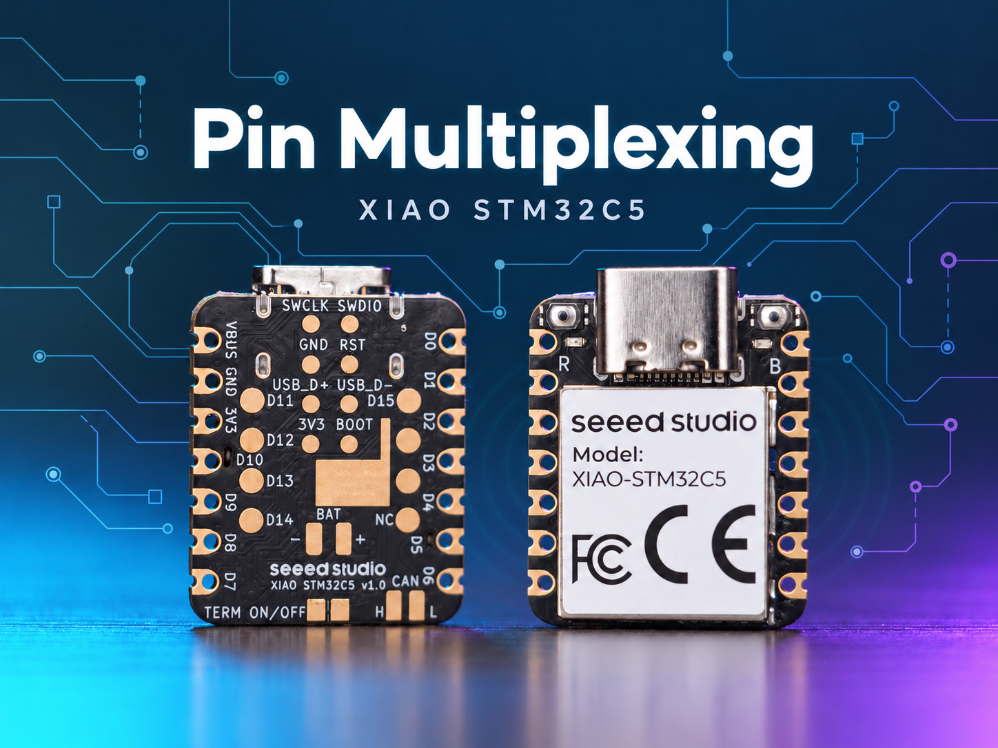
概述
XIAO STM32C5 具有丰富的引脚资源,原生支持使用 Digital、Analog、SPI 和 IIC 等多种标准外设接口进行开发。本文通过实际应用案例展示相关实现方法。
本教程基于 PlatformIO 构建系统和 Zephyr RTOS 开发。 如果你还不熟悉如何在 PlatformIO 下为 XIAO STM32C5 创建项目,可以跳转到 Getting Started With Seeed Studio XIAO STM32C5
数字 IO
数字引脚主要通过输出高、低电平逻辑,实现对外部传感器和执行器的通断控制。结合 Grove Base for XIAO 扩展板和标准 Grove 外设模块,本节将详细说明 XIAO STM32C5 上数字引脚的底层驱动逻辑以及实际调用方式。
硬件准备
| Seeed Studio XIAO STM32C5 | Seeed Studio Grove Base for XIAO | Grove - LED Pack |
|---|---|---|
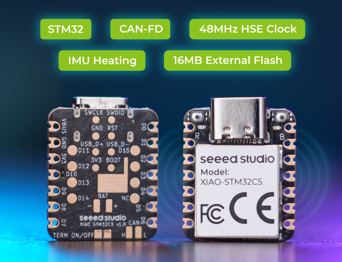 |  |  |
软件准备
根据 XIAO STM32C5 的引脚定义,可以选择 D1 作为 Grove - LED Pack 的控制引脚。
- 关于 XIAO STM32C5 的引脚定义,请点击 XIAO STM32C5 Pin List 查看详情。
编写 main.c 程序
/*
 * Copyright (c) 2026 Seeed Technology Co., Ltd.
 * SPDX-License-Identifier: Apache-2.0
 *
 * Blinky example for XIAO STM32C5 with TinyUF2 bootloader support.
 * Based on Zephyr samples/basic/blinky.
 *
 * The 1200-bps UF2 bootloader trigger is armed automatically by the
 * board support package — no code changes needed in this example.
 */

#include <zephyr/kernel.h>
#include <zephyr/drivers/gpio.h>

#define SLEEP_TIME_MS 1000

#define D1_PIN 1

static const struct device *const d1_gpio = DEVICE_DT_GET(DT_NODELABEL(gpioa));

int main(void)
{
	int ret;
	bool led_state = true;

	if (!device_is_ready(d1_gpio)) {
		return 0;
	}

	ret = gpio_pin_configure(d1_gpio, D1_PIN, GPIO_OUTPUT_ACTIVE);
	if (ret < 0) {
		return 0;
	}

	while (1) {
		ret = gpio_pin_toggle(d1_gpio, D1_PIN);
		if (ret < 0) {
			return 0;
		}

		led_state = !led_state;
		printk("LED state: %s\n", led_state ? "ON" : "OFF");
		k_msleep(SLEEP_TIME_MS);
	}

	return 0;
}
结果
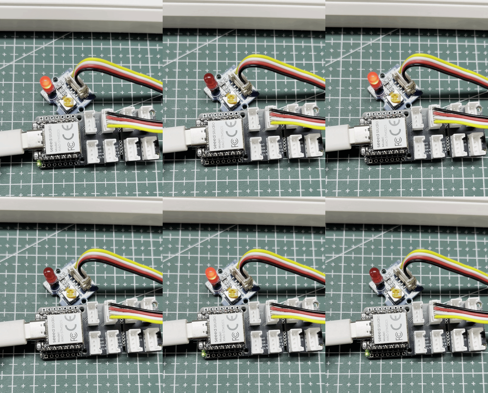
烧录固件后,红色 LED 会闪烁。
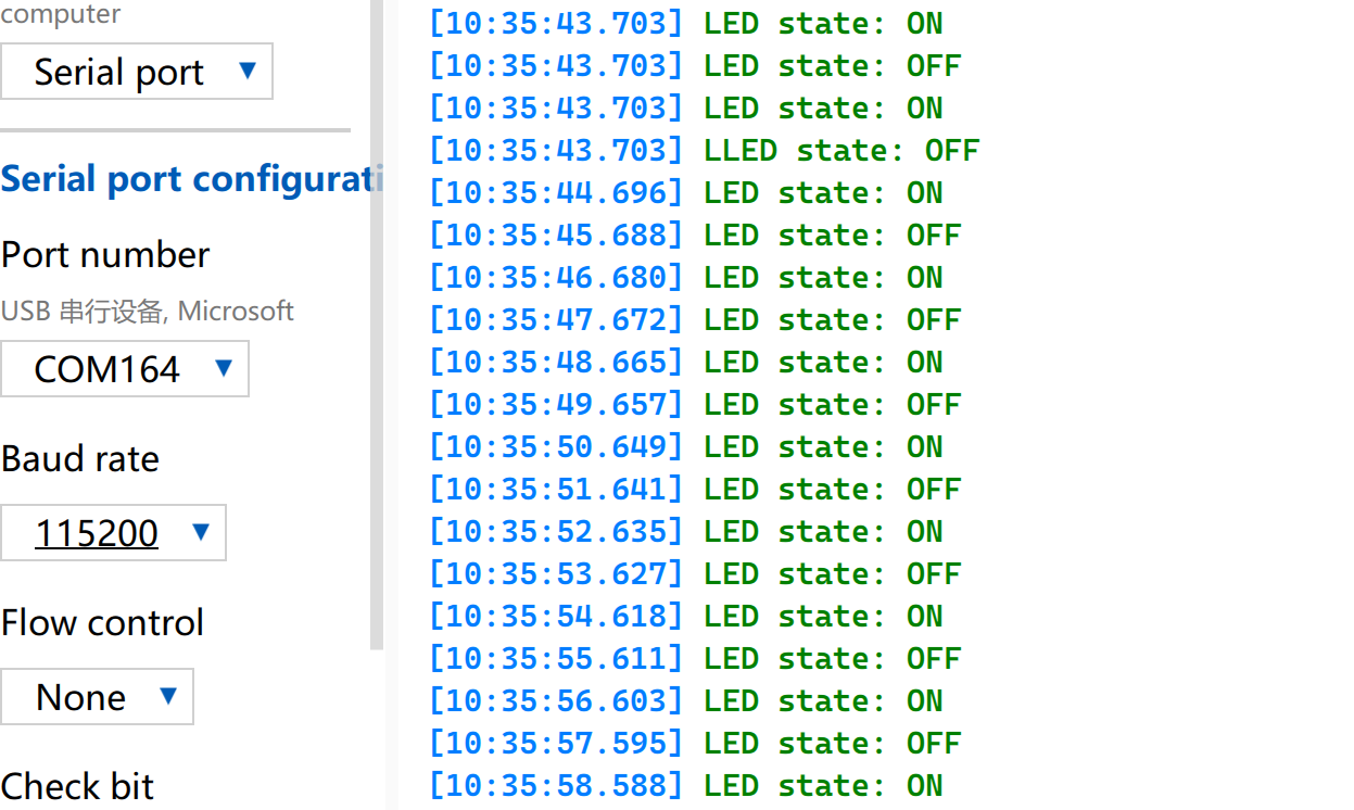
打开串口监视器,并将波特率设置为 115200。
PWM
PWM 是一种基于数字输出 GPIO 实现的定时波形输出功能。它以固定频率快速切换引脚电平,并在单个周期内动态调节高电平的占空比,从而向外设输出等效的模拟信号。在实际工程应用中,PWM 被广泛用于舵机的精确角度控制以及 LED 的平滑亮度调节。
驱动舵机
硬件准备
| Seeed Studio XIAO STM32C5 | Seeed Studio Grove Base for XIAO | Grove - Servo |
|---|---|---|
| |  |
软件准备
根据 XIAO STM32C5 的引脚定义,D0 可以作为 Grove-Servo 的控制引脚。
- 关于 XIAO STM32C5 的引脚定义,请点击 XIAO STM32C5 Pin List 查看详情。
- 修改
app.overlay文件。在 XIAO STM32C5 上,D0 对应 PA0 引脚。通过在 DeviceTree 中将 PA0 配置为 AF1 复用功能,可以使用 TIM2_CH1 输出 PWM 信号。
app.overlay
#include <zephyr/dt-bindings/pwm/pwm.h>

&{/pwmleds} {
	servo: servo {
		pwms = <&pwm2 1 PWM_MSEC(20) PWM_POLARITY_NORMAL>;
	};
};

&timers2 {
	st,prescaler = <143>;
	status = "okay";

	pwm2: pwm {
		pinctrl-0 = <&tim2_ch1_pa0>;
		pinctrl-names = "default";
		status = "okay";
	};
};
- 修改
prj.conf文件以启用相关 PWM 配置。
CONFIG_PWM=y
- 编写 main.c 程序,实现 PWM 舵机控制功能,并配置 PWM 周期等参数。
main.c
#include <zephyr/kernel.h>
#include <zephyr/device.h>
#include <zephyr/drivers/pwm.h>
#include <zephyr/sys/printk.h>

#define SERVO_PERIOD_NS PWM_MSEC(20)
#define SERVO_MIN_NS PWM_USEC(500)
#define SERVO_MAX_NS PWM_USEC(2500)
#define SERVO_CHANNEL 1
#define STEP_FWD_MS 10
#define STEP_RET_MS 30

static const struct device *pwm_dev = DEVICE_DT_GET(DT_NODELABEL(pwm2));

static int set_angle(int degrees)
{
	uint32_t pulse = SERVO_MIN_NS +
		(uint32_t)((uint64_t)degrees *
		(SERVO_MAX_NS - SERVO_MIN_NS) / 180U);

	return pwm_set(pwm_dev, SERVO_CHANNEL, SERVO_PERIOD_NS, pulse,
		PWM_POLARITY_NORMAL);
}

int main(void)
{
	printk("=== boot ===\n");

	if (!device_is_ready(pwm_dev)) {
		printk("Error: PWM device not ready\n");
		return -1;
	}

	printk("Servo control started on D0\n");

	while (1) {
		for (int angle = 0; angle <= 180; angle++) {
			if (set_angle(angle)) {
				printk("PWM error at %d deg\n", angle);
			} else {
				printk("Angle: %d deg\n", angle);
			}
			k_msleep(STEP_FWD_MS);
		}

		for (int angle = 180; angle >= 0; angle--) {
			if (set_angle(angle)) {
				printk("PWM error at %d deg\n", angle);
			} else {
				printk("Angle: %d deg\n", angle);
			}
			k_msleep(STEP_RET_MS);
		}
	}

	return 0;
}
结果
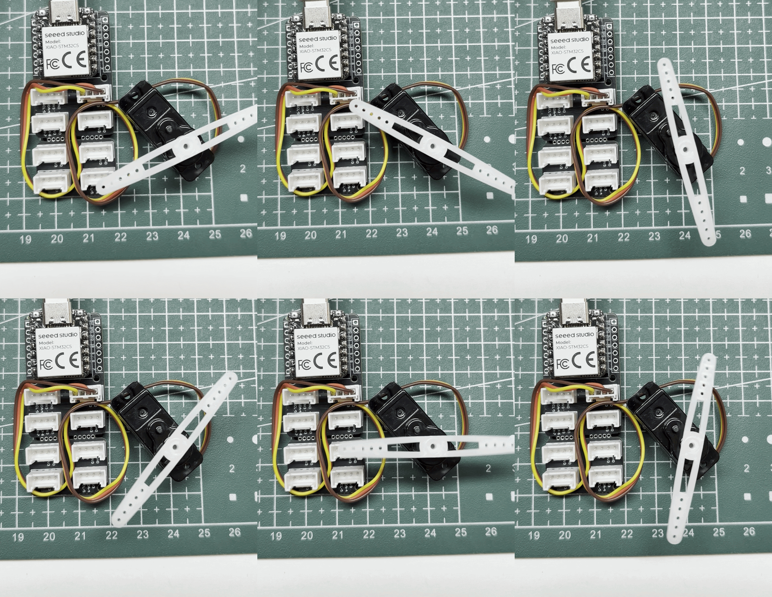
指令角度从 0° 开始,每 10 ms 增加 1° 直到 180°,然后每 30 ms 减少 1°。实际运动速度取决于舵机本身。
控制蜂鸣器
Seeed Studio Expansion Board Base for XIAO 配备了一个板载无源电磁蜂鸣器,可由 PWM 信号驱动。通过调节 PWM 的频率、占空比和输出时序,可以控制蜂鸣器声音的音调、音量和持续时间,从而实现按键提示音、状态提醒和报警等功能。
硬件准备
| Seeed Studio XIAO STM32C5 | Seeed Studio Expansion Board Base for XIAO |
|---|---|
|  |
软件准备
- 关于 XIAO STM32C5 的引脚分布,请点击 XIAO STM32C5 Pin List 查看详情。
- 修改
app.overlay文件。在 XIAO STM32C5 上,A3/D3 对应 PA3 引脚,该引脚通过 Seeed Studio Expansion Board Base for XIAO 上的 2N7002PW MOSFET 连接到板载 LET5020CS-03L 无源电磁蜂鸣器。通过在 DeviceTree 中将 PA3 配置为 AF1 复用功能,TIM2_CH4 可以输出周期为 250 μs、占空比为 50% 的 4 kHz PWM 信号来驱动蜂鸣器。
app.overlay
#include <zephyr/dt-bindings/gpio/gpio.h>
#include <zephyr/dt-bindings/input/input-event-codes.h>
#include <zephyr/dt-bindings/pwm/pwm.h>

/ {
	buttons {
		compatible = "gpio-keys";

		expansion_button: button {
			gpios = <&xiao_d 1 (GPIO_PULL_UP | GPIO_ACTIVE_LOW)>;
			zephyr,code = <INPUT_KEY_0>;
		};
	};

	pwmleds {
		compatible = "pwm-leds";

		expansion_buzzer: buzzer {
			/* LET5020CS-03L: 4 kHz resonant frequency. */
			pwms = <&pwm2 4 PWM_USEC(250) PWM_POLARITY_NORMAL>;
		};
	};

	aliases {
		sw1 = &expansion_button;
		buzzer = &expansion_buzzer;
	};
};

&timers2 {
	st,prescaler = <143>;
	status = "okay";

	pwm2: pwm {
		pinctrl-0 = <&tim2_ch4_pa3>;
		pinctrl-names = "default";
		status = "okay";
	};
};
- 修改
prj.conf文件以启用相关 PWM 配置。
CONFIG_GPIO=y
CONFIG_PWM=y
- 修改 main.c 程序。
main.c
/*
 * Copyright (c) 2026 Seeed Technology Co., Ltd.
 * SPDX-License-Identifier: Apache-2.0
 *
 * Expansion Board Base for XIAO buzzer demo:
 * press the onboard button (D1) to sound the onboard buzzer (A3/D3).
 */

#include <zephyr/kernel.h>
#include <zephyr/drivers/gpio.h>
#include <zephyr/drivers/pwm.h>
#include <zephyr/sys/printk.h>

static const struct gpio_dt_spec button =
	GPIO_DT_SPEC_GET(DT_ALIAS(sw1), gpios);
static const struct pwm_dt_spec buzzer =
	PWM_DT_SPEC_GET(DT_ALIAS(buzzer));

int main(void)
{
	bool buzzer_on = false;
	int ret;

	if (!gpio_is_ready_dt(&button) || !pwm_is_ready_dt(&buzzer)) {
		printk("Button or buzzer device not ready\n");
		return -1;
	}

	ret = gpio_pin_configure_dt(&button, GPIO_INPUT);
	if (ret < 0) {
		printk("Button configuration failed: %d\n", ret);
		return ret;
	}

	ret = pwm_set_dt(&buzzer, buzzer.period, 0);
	if (ret < 0) {
		printk("Buzzer configuration failed: %d\n", ret);
		return ret;
	}

	printk("Press the D1 button to sound the A3 buzzer\n");

	while (1) {
		int pressed = gpio_pin_get_dt(&button);

		if (pressed < 0) {
			printk("Button read failed: %d\n", pressed);
			return pressed;
		}

		if ((pressed != 0) != buzzer_on) {
			ret = pwm_set_dt(&buzzer, buzzer.period,
					 pressed ? buzzer.period / 2U : 0U);
			if (ret < 0) {
				printk("Buzzer control failed: %d\n", ret);
				return ret;
			}

			buzzer_on = pressed != 0;
			printk("Buzzer: %s\n", buzzer_on ? "ON" : "OFF");
		}

		k_msleep(20);
	}
}
结果
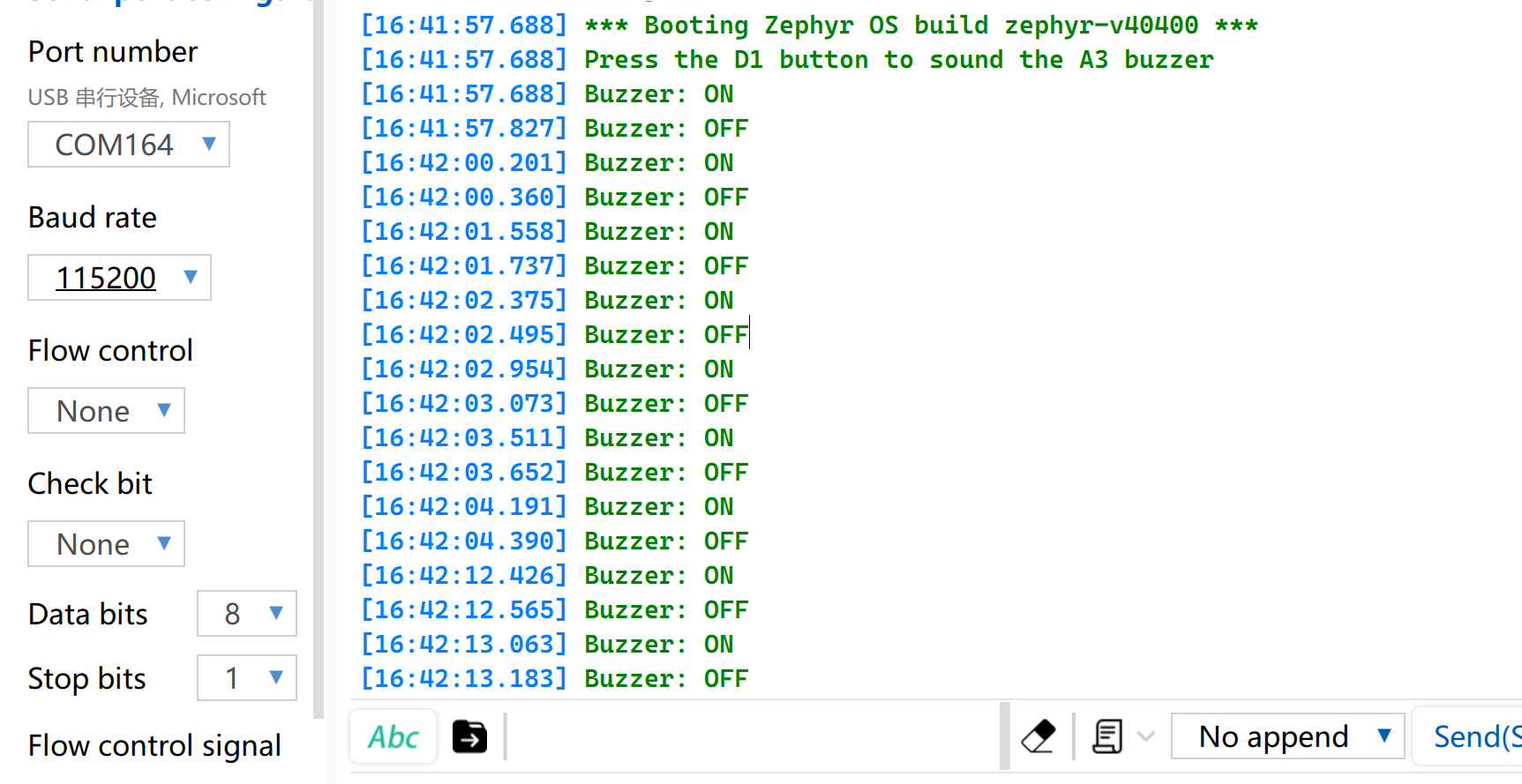
当按下 Seeed Studio Expansion Board Base for XIAO 上的 Button 按键时,蜂鸣器会发声。打开串口监视器并将波特率设置为 115200,即可打印出对应的状态信息。
模拟量
模拟 I/O 基于模数转换器(ADC),主要用于采集外部传感器输出的连续模拟电压信号。获取原始数字采样值(Raw Data)后,可以通过特定的线性或非线性转换算法,将其映射为实际的工程测量值。该功能广泛应用于电池电压采样,以及对土壤湿度、环境温度等物理量的实时监测场景。
硬件准备
| Seeed Studio XIAO STM32C5 | Seeed Studio Grove Base for XIAO | Grove - Capacitive Soil Moisture Sensor |
|---|---|---|
| |  |
软件准备
- 修改
app.overlay文件。在 XIAO STM32C5 的板级 DTS 中,A0 已经完整配置为 PA0、ADC1 通道 0,分辨率为 12 位。因此,在app.overlay中,zephyr,user应该引用 ADC1 通道 0。
/ {
	zephyr,user {
		io-channels = <&adc1 0>;
	};
};
- 修改
prj.conf文件以启用 ADC 相关配置。
CONFIG_ADC=y
- 修改 main.c 程序。
main.c
#include <zephyr/kernel.h>
#include <zephyr/drivers/adc.h>
#include <zephyr/sys/printk.h>

static const struct adc_dt_spec adc_ch =
	ADC_DT_SPEC_GET(DT_PATH(zephyr_user));

int main(void)
{
	int ret;
	int16_t buffer;
	struct adc_sequence sequence = {
		.buffer = &buffer,
		.buffer_size = sizeof(buffer),
	};

	if (!adc_is_ready_dt(&adc_ch)) {
		printk("ADC not ready\n");
		return -1;
	}

	ret = adc_channel_setup_dt(&adc_ch);
	if (ret < 0) {
		printk("ADC channel setup failed: %d\n", ret);
		return ret;
	}

	adc_sequence_init_dt(&adc_ch, &sequence);
	printk("A0 ADC example started\n");

	while (1) {
		ret = adc_read_dt(&adc_ch, &sequence);
		if (ret < 0) {
			printk("ADC read error: %d\n", ret);
		} else {
			printk("ADC raw: %d\n", buffer);
		}

		k_msleep(500);
	}
}
结果
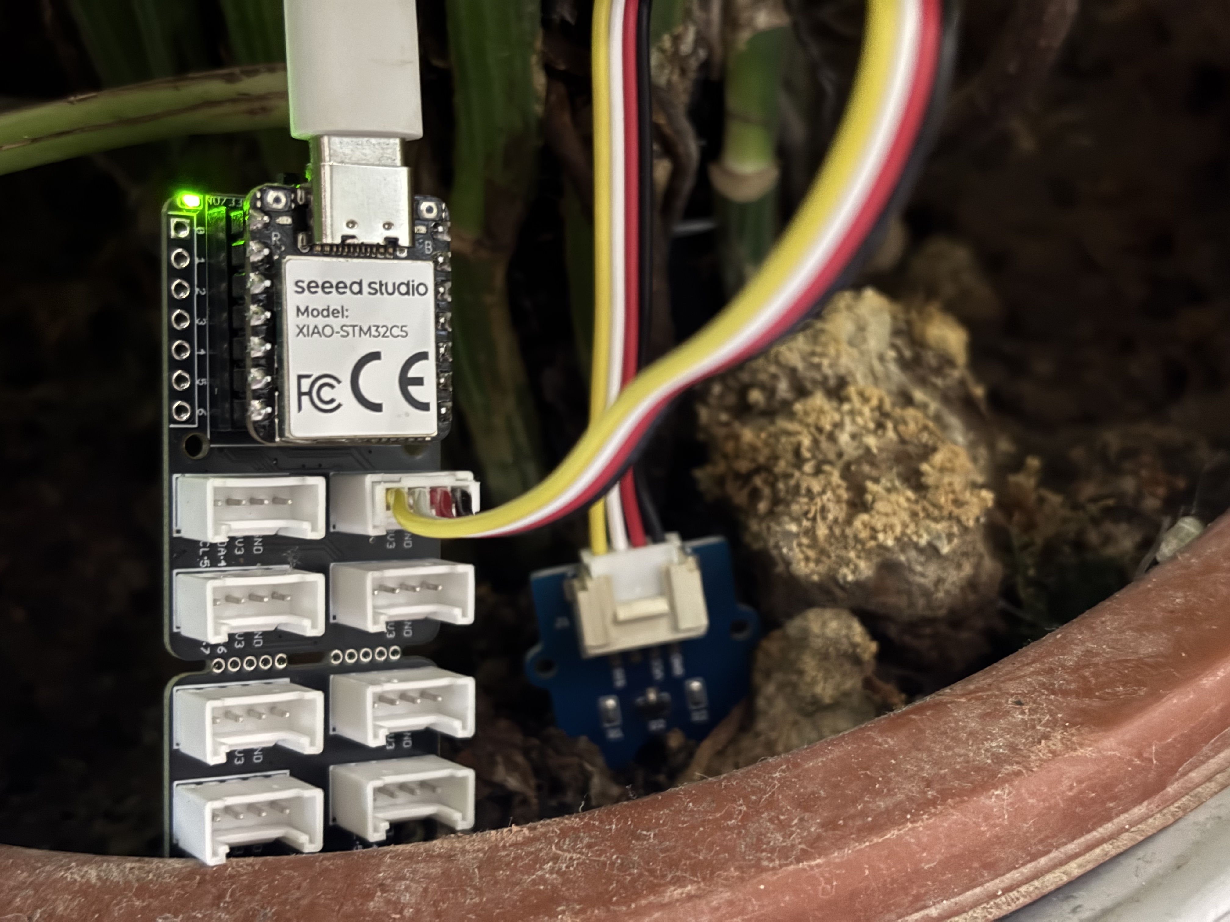
烧录程序后,将 Grove-Capacitive Soil Moisture Sensor 插入家用盆栽中。
在电脑上打开串口助手,观察输出数值。
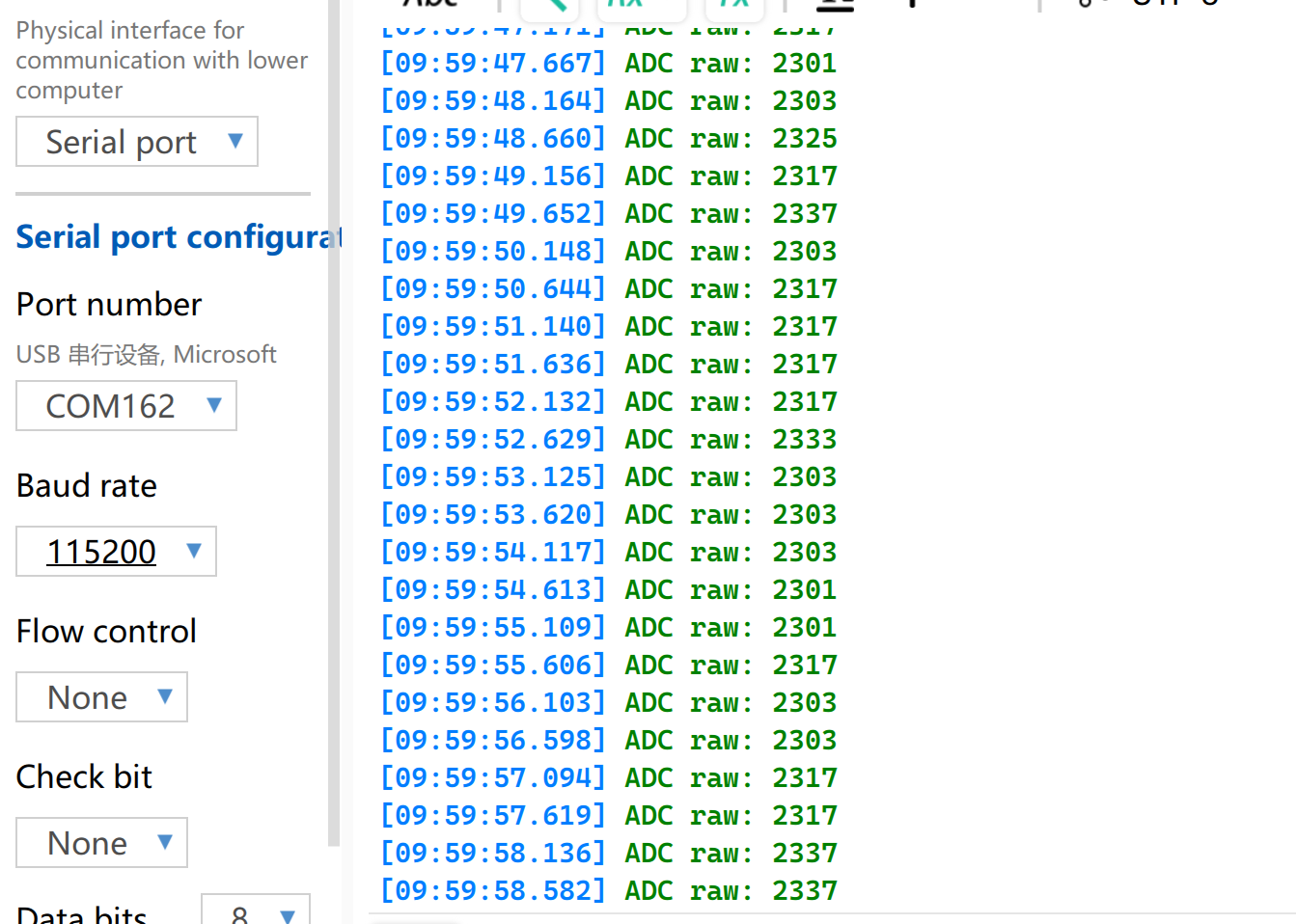
电压参考读数表
| 状态 | 传感器输出电压 | ADC 原始值 |
|---|---|---|
| 在空气中(干燥) | ~2.0–2.4V | ~3400–4095 |
| 在湿润土壤中 | ~1.3–1.8V | ~2200–3000 |
| 完全浸没在水中 | ~0.8–1.2V | ~1365–2048 |
在不同环境条件下,测量结果可能会有所差异。请以实际测量值为准。
UART
通用异步收发器(UART)是一种标准的异步串行通信协议。它不需要外部时钟信号进行同步,而是依靠通信双方预先设定的波特率来实现异步数据收发。在物理连线方面,只需将设备的 TX 和 RX 引脚交叉连接并共地,即可建立全双工数据链路。由于硬件成本极低且支持收发同时进行,UART 被广泛应用于嵌入式系统中的控制台日志输出、模块化外设调试以及低带宽点对点数据通信。
硬件准备
| Seeed Studio XIAO STM32C5 | USB 转 TTL 转换器 |
|---|---|
|  |
软件准备
- 修改 app.overlay。在 XIAO STM32C5 上,D6 对应 PA9 / USART1_TX,D7 对应 PA10 / USART1_RX。对应的 DeviceTree 节点为 usart1。将默认波特率设置为 115200。
/ {
	chosen {
		zephyr,console = &usart1;
		zephyr,shell-uart = &usart1;
	};
};
- 修改 prj.conf 以启用串口控制台支持。
CONFIG_SERIAL=y
CONFIG_CONSOLE=y
CONFIG_UART_CONSOLE=y
CONFIG_UART_INTERRUPT_DRIVEN=y
CONFIG_PRINTK=y
- 程序在启动时打印 UART 引脚映射,回显接收到的数据,并周期性打印运行状态信息。
main.c
#include <zephyr/kernel.h>
#include <zephyr/device.h>
#include <zephyr/drivers/uart.h>
#include <zephyr/sys/printk.h>

#define RX_BUFFER_SIZE 128
#define RX_TIMEOUT_MS  50

static const struct device *const uart = DEVICE_DT_GET(DT_NODELABEL(usart1));
K_MSGQ_DEFINE(rx_msgq, sizeof(uint8_t), RX_BUFFER_SIZE, 1);

static void uart_rx_isr(const struct device *dev, void *user_data)
{
	uint8_t data[16];
	int length;

	ARG_UNUSED(user_data);

	if (!uart_irq_update(dev)) {
		return;
	}

	while (uart_irq_rx_ready(dev)) {
		length = uart_fifo_read(dev, data, sizeof(data));
		if (length <= 0) {
			break;
		}

		for (int i = 0; i < length; i++) {
			(void)k_msgq_put(&rx_msgq, &data[i], K_NO_WAIT);
		}
	}
}

int main(void)
{
	char rx_buffer[RX_BUFFER_SIZE];
	size_t rx_length = 0;
	int64_t last_rx_time = 0;
	int64_t last_debug_time = k_uptime_get();

	if (!device_is_ready(uart)) {
		return -1;
	}

	if (uart_irq_callback_user_data_set(uart, uart_rx_isr, NULL) < 0) {
		return -1;
	}

	uart_irq_rx_enable(uart);

	printk("\r\nXIAO STM32C5 UART demo\r\n");
	printk("D6: TX, D7: RX, 115200 8N1\r\n");
	printk("Type a character to test RX and echo.\r\n");

	while (1) {
		uint8_t data;
		int64_t now;

		while (k_msgq_get(&rx_msgq, &data, K_NO_WAIT) == 0) {
			last_rx_time = k_uptime_get();

			if (data == '\r' || data == '\n') {
				if (rx_length > 0) {
					rx_buffer[rx_length] = '\0';
					printk("RX: %s\r\n", rx_buffer);
					rx_length = 0;
				}
			} else if (rx_length < RX_BUFFER_SIZE - 1) {
				rx_buffer[rx_length++] = (char)data;
			}
		}

		now = k_uptime_get();

		/* Also print strings sent without a trailing CR/LF. */
		if (rx_length > 0 && now - last_rx_time >= RX_TIMEOUT_MS) {
			rx_buffer[rx_length] = '\0';
			printk("RX: %s\r\n", rx_buffer);
			rx_length = 0;
		}

		if (now - last_debug_time >= 1000) {
			printk("UART debug: system running\r\n");
			last_debug_time = now;
		}

		k_msleep(1);
	}
}
结果
- 按照下表顺序进行接线
| XIAO STM32C5 | CH340 |
|---|---|
| GND | GND |
| D6 - TX | RX |
| D7 - RX | TX |
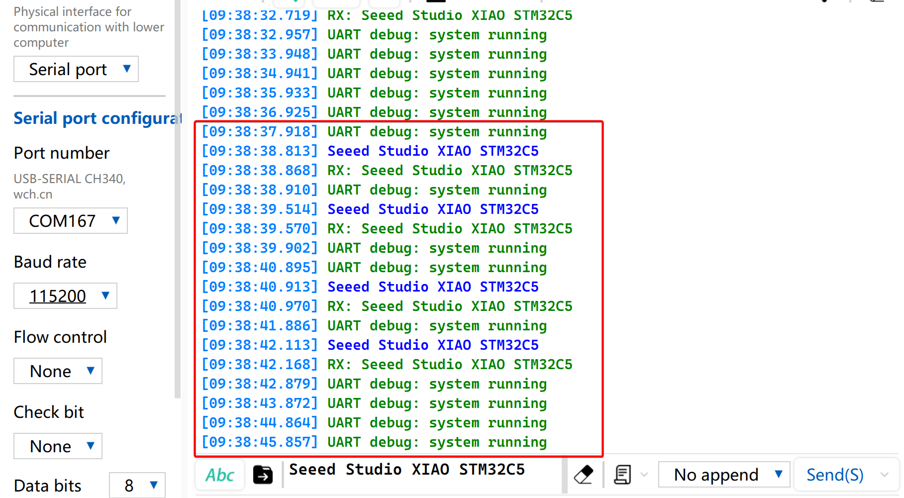
- 你可以使用串口监视器查看运行时信息。也可以通过串口发送数据,接收到的数据会被打印到控制台。
I2C
I2C 是一种同步、半双工的数据通信协议。它通过 SCL 时钟线和 SDA 数据线进行寻址,实现多设备连接,常用于读取对传输速率要求较高的传感器数据,例如 IMU 和温湿度传感器,或用于 OLED 显示输出。
硬件准备
| Seeed Studio XIAO STM32C5 | Seeed Studio Expansion Board Base for XIAO |
|---|---|
| |
软件准备
- 在 XIAO STM32C5 上,D4 对应 PB7 / I2C1_SDA,D5 对应 PB6 / I2C1_SCL。由于 I2C1 已在板级 DTS 中启用,在 I2C 地址 0x3C 处添加一个 SSD1306 显示节点。按如下方式修改 app.overlay:
/ {
	chosen {
		zephyr,display = &oled;
	};
};

&i2c1 {
	oled: ssd1306@3c {
		compatible = "solomon,ssd1306";
		reg = <0x3c>;
		width = <128>;
		height = <64>;
		segment-offset = <0>;
		page-offset = <0>;
		display-offset = <0>;
		multiplex-ratio = <63>;
		segment-remap;
		com-invdir;
		prechargep = <0x22>;
	};
};
- 修改
prj.conf文件以启用 I2C 和显示相关配置。
CONFIG_DISPLAY=y
CONFIG_CHARACTER_FRAMEBUFFER=y
CONFIG_HEAP_MEM_POOL_SIZE=2048
- 编写主函数以设置字符串的显示位置和功能。
main.c
#include <zephyr/device.h>
#include <zephyr/display/cfb.h>
#include <zephyr/sys/printk.h>

int main(void)
{
	const struct device *display = DEVICE_DT_GET(DT_CHOSEN(zephyr_display));

	if (!device_is_ready(display)) {
		printk("OLED not ready\n");
		return -1;
	}

	if (cfb_framebuffer_init(display)) {
		return -1;
	}

	cfb_framebuffer_clear(display, true);
	cfb_framebuffer_set_font(display, 0);
	cfb_print(display, "XIAO STM32C5", 4, 8);
	cfb_print(display, "Hello World", 9, 32);
	cfb_framebuffer_finalize(display);
	display_blanking_off(display);

	return 0;
}
结果
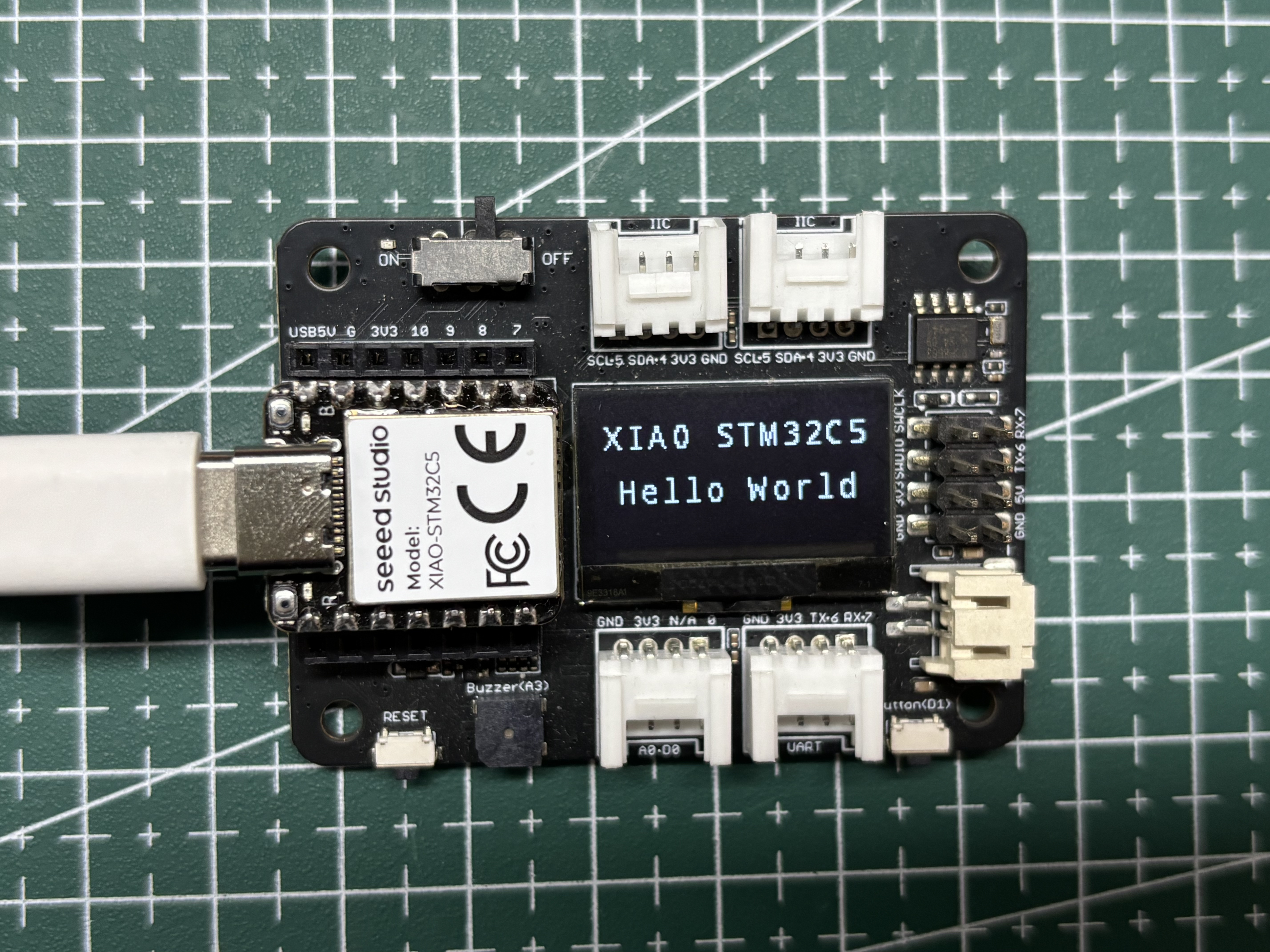
程序运行后,OLED 会显示 XIAO STM32C5 Hello World。
SPI
SPI 是一种高速、同步且全双工的通信协议。与异步通信不同,SPI 依赖专用的 SCLK 时钟线来实现精确的数据同步。它通常采用由 MOSI、MISO 和片选 CS/SS 引脚组成的经典四线硬件拓扑结构。凭借独立的数据发送和接收通道以及较高的总线时钟频率,SPI 具备出色的数据吞吐能力,被广泛应用于对带宽要求较高的外设驱动场景,例如 Flash 和 SD 卡等大容量存储设备、高分辨率高刷新率屏幕显示以及高频采样传感器。
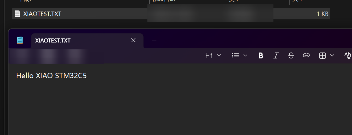
接下来将演示一个 SD 卡示例:读取 SD 卡容量,并向其中写入名为 XIAOTEST.TXT 的文件,内容为 Hello XIAO STM32C5。
硬件准备
| Seeed Studio XIAO STM32C5 | Seeed Studio Expansion Board Base for XIAO |
|---|---|
| |
此外,你还需要准备一张格式化为 FAT32 的 SD 卡,存储容量为 32 GB 或更小。
软件准备
- XIAO STM32C5 的默认 SPI 总线引脚为 D8 - SPI_SCK、D9 - SPI_MISO 和 D10 - SPI_MOSI。其在板级 DTS 中对应的节点为
SPI3。此外,还需要选择一个 CS 片选引脚,这里选择 D2。
app.overlay
#include <zephyr/dt-bindings/gpio/gpio.h>

/ {
	chosen {
		zephyr,display = &oled;
	};
};

&i2c1 {
	oled: ssd1306@3c {
		compatible = "solomon,ssd1306";
		reg = <0x3c>;
		width = <128>;
		height = <64>;
		segment-offset = <0>;
		page-offset = <0>;
		display-offset = <0>;
		multiplex-ratio = <63>;
		segment-remap;
		com-invdir;
		prechargep = <0x22>;
	};
};

&spi3 {
	cs-gpios = <&gpioa 2 GPIO_ACTIVE_LOW>; /* D2: SD card CS */

	sdhc0: sdhc@0 {
		compatible = "zephyr,sdhc-spi-slot";
		reg = <0>;
		status = "okay";
		spi-max-frequency = <8000000>;

		mmc {
			compatible = "zephyr,sdmmc-disk";
			disk-name = "SD";
			status = "okay";
		};
	};
};
- 修改 prj.conf 以启用 SPI 相关配置。
CONFIG_DISK_ACCESS=y
CONFIG_FILE_SYSTEM=y
CONFIG_FAT_FILESYSTEM_ELM=y
CONFIG_SDHC=y
CONFIG_SDMMC_SUBSYS=y

CONFIG_DISPLAY=y
CONFIG_CHARACTER_FRAMEBUFFER=y

CONFIG_MAIN_STACK_SIZE=4096
CONFIG_HEAP_MEM_POOL_SIZE=4096
CONFIG_PRINTK=y
- 修改 main.c 程序。
main.c
/*
* XIAO STM32C5 SD card read/write example.
*
* SD card (SPI3, FAT32):
* D8 - SCK
* D9 - MISO
* D10 - MOSI
* D2 - CS
*
* 0.96-inch SSD1306 OLED (128x64, I2C address 0x3C):
* D4 - SDA
* D5 - SCL
*
* The example waits 500 ms after power-on, reads the SD card capacity,
* creates /XIAOTEST.TXT, writes "Hello XIAO STM32C5", then reads the file
* back for verification. Card size, write progress, and the final result
* are displayed on the OLED and printed through the USB CDC console.
*/
#include <errno.h>
#include <string.h>
#include <zephyr/device.h>
#include <zephyr/display/cfb.h>
#include <zephyr/fs/fs.h>
#include <zephyr/kernel.h>
#include <zephyr/storage/disk_access.h>
#include <zephyr/sys/printk.h>
#include <ff.h>
#define DISK_NAME "SD"
#define MOUNT_POINT "/SD:"
#define TEST_FILE MOUNT_POINT "/XIAOTEST.TXT"
#define TEST_TEXT "Hello XIAO STM32C5"
static const struct device *const oled = DEVICE_DT_GET(DT_CHOSEN(zephyr_display));
static FATFS fat_fs;
static struct fs_mount_t mount = {
.type = FS_FATFS,
.fs_data = &fat_fs,
.mnt_point = MOUNT_POINT,
};
static void oled_show(const char *line1, const char *line2,
const char *line3, const char *line4)
{
cfb_framebuffer_clear(oled, false);
cfb_print(oled, line1, 0, 0);
cfb_print(oled, line2, 0, 16);
cfb_print(oled, line3, 0, 32);
cfb_print(oled, line4, 0, 48);
cfb_framebuffer_finalize(oled);
}
int main(void)
{
uint32_t sector_count;
uint32_t sector_size;
uint64_t size_mb;
char size_line[24];
char readback[sizeof(TEST_TEXT)] = { 0 };
struct fs_file_t file;
int ret;
/* Allow the USB CDC console time to become available after power-on. */
k_msleep(500);
printk("\n=== XIAO STM32C5 SD Card Test ===\n");
printk("SD: D8=SCK, D9=MISO, D10=MOSI, D2=CS\n");
printk("OLED: D4=SDA, D5=SCL\n");
if (!device_is_ready(oled) || cfb_framebuffer_init(oled) != 0) {
printk("OLED initialization failed\n");
return -1;
}
cfb_framebuffer_set_font(oled, 0);
display_blanking_off(oled);
oled_show("SD Card Test", "Initializing...", "", "");
/* Initialize the SD card and read its physical capacity. */
ret = disk_access_ioctl(DISK_NAME, DISK_IOCTL_CTRL_INIT, NULL);
if (ret != 0) {
oled_show("SD Card Test", "SD init FAILED", "Check card/wires", "");
printk("SD card initialization failed: %d\n", ret);
return ret;
}
printk("SD card initialized\n");
ret = disk_access_ioctl(DISK_NAME, DISK_IOCTL_GET_SECTOR_COUNT,
§or_count);
ret |= disk_access_ioctl(DISK_NAME, DISK_IOCTL_GET_SECTOR_SIZE,
§or_size);
if (ret != 0) {
oled_show("SD Card Test", "Read size FAILED", "", "");
printk("Failed to read SD card capacity: %d\n", ret);
return ret;
}
size_mb = ((uint64_t)sector_count * sector_size) / (1024U * 1024U);
snprintk(size_line, sizeof(size_line), "Size: %llu MB", size_mb);
oled_show("SD Card Test", size_line, "Mounting FAT32", "");
printk("SD card size: %llu MB\n", size_mb);
printk("Mounting FAT32 file system...\n");
ret = fs_mount(&mount);
if (ret != 0) {
oled_show("SD Card Test", size_line, "Mount FAILED", "Use FAT32 card");
printk("FAT32 mount failed: %d\n", ret);
return ret;
}
printk("FAT32 mounted\n");
/* Create or replace the test file and write the requested text. */
oled_show("SD Card Test", size_line, "Writing file...", "");
printk("Writing %s...\n", TEST_FILE);
fs_file_t_init(&file);
ret = fs_open(&file, TEST_FILE, FS_O_CREATE | FS_O_WRITE | FS_O_TRUNC);
if (ret == 0) {
ret = fs_write(&file, TEST_TEXT, sizeof(TEST_TEXT) - 1);
if (ret == sizeof(TEST_TEXT) - 1) {
ret = fs_sync(&file);
} else if (ret >= 0) {
ret = -EIO;
}
fs_close(&file);
}
/* Read the file back so SUCCESS means the stored data was verified. */
if (ret == 0) {
fs_file_t_init(&file);
ret = fs_open(&file, TEST_FILE, FS_O_READ);
if (ret == 0) {
ret = fs_read(&file, readback, sizeof(readback) - 1);
fs_close(&file);
if (ret == sizeof(TEST_TEXT) - 1 &&
strcmp(readback, TEST_TEXT) == 0) {
ret = 0;
} else if (ret >= 0) {
ret = -EIO;
}
}
}
fs_unmount(&mount);
if (ret == 0) {
oled_show("SD Card Test", size_line, "Write: SUCCESS", "File verified");
printk("Write successful: %s\n", TEST_TEXT);
printk("Readback verification successful\n");
} else {
oled_show("SD Card Test", size_line, "Write: FAILED", "Check SD card");
printk("SD card write failed: %d\n", ret);
}
return ret;
}
结果
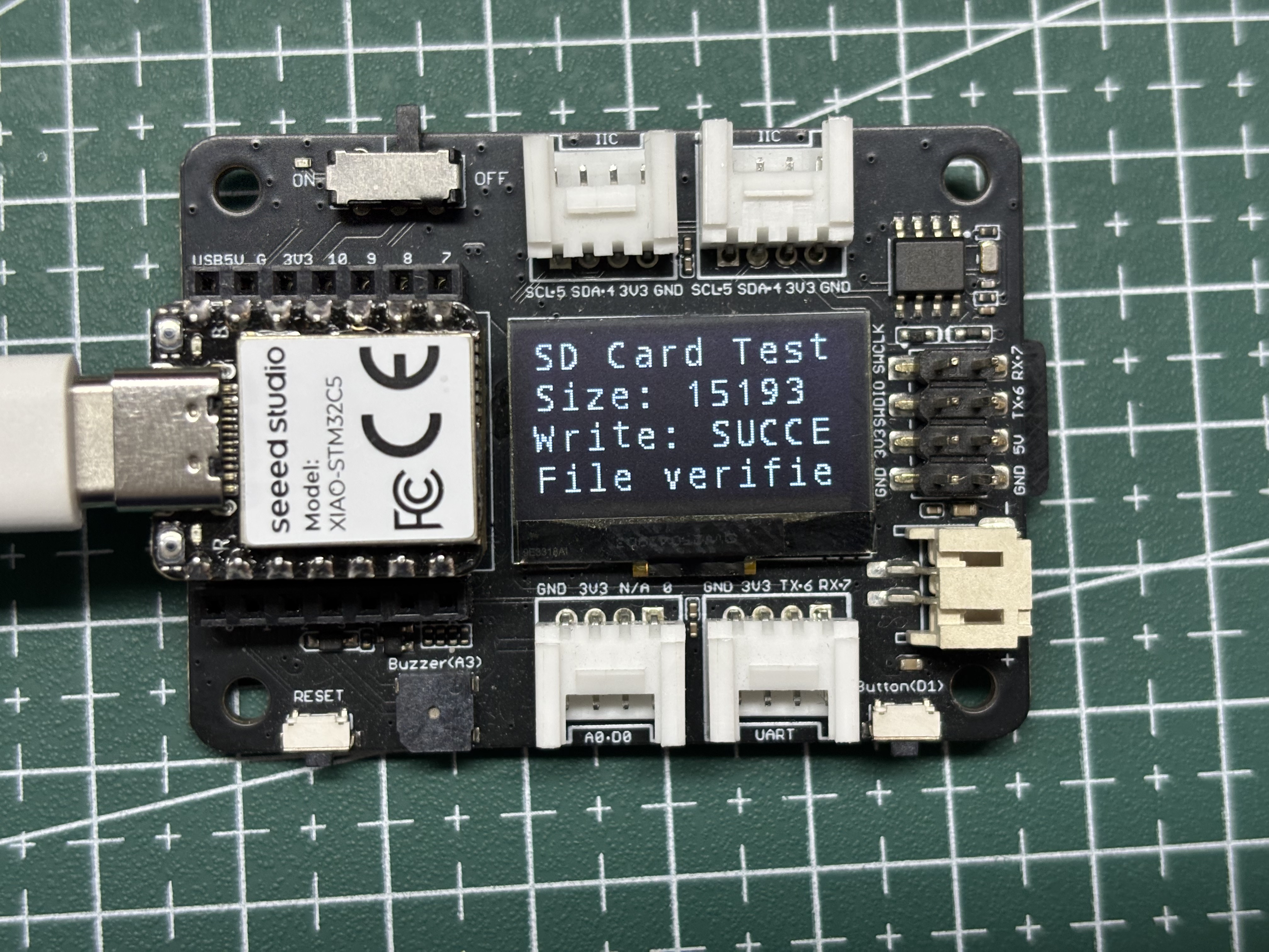
- 屏幕将显示 SD 卡挂载状态、SD 卡容量以及文件是否写入成功等信息。
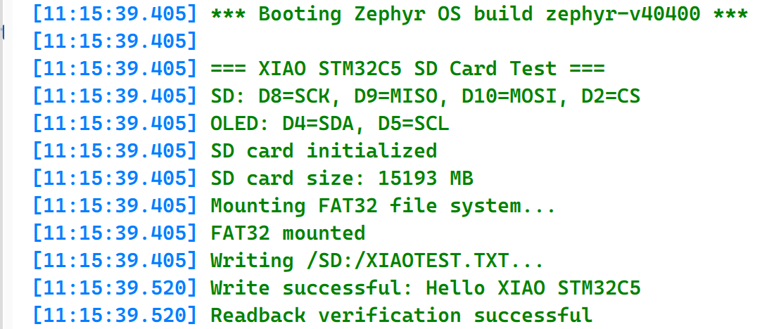
- 打开串口监视器查看文件写入信息。
- 取出 SD 卡,将其插入连接到电脑的读卡器中,以检查写入的文件。
RTC
RTC(实时时钟)是一种低功耗硬件定时外设,用于持续保持精确的时间和日历信息。它通常由独立的低频时钟源驱动,例如 32.768 kHz 晶体振荡器,并且在主系统断电时可以通过后备电源域继续运行。RTC 外设通常支持秒、分、时、日期、星期、月份和年份,以及闹钟、周期性唤醒和时间戳等功能。RTC 广泛应用于需要长期计时、定时唤醒、事件记录和低功耗运行的场景,例如数据记录仪、工业控制器、智能家居设备和便携式仪器。
Round Display for Seeed Studio XIAO 板载了 RTC 电路。下面演示 RTC 时钟功能在 XIAO STM32C5 上的工作情况。
硬件准备
| Seeed Studio XIAO STM32C5 | Round Display for Seeed Studio XIAO |
|---|---|
|  |
软件准备
- 修改 app.overlay:Round Display for Seeed Studio XIAO 采用 240 × 240 GC9A01 LCD。在 XIAO STM32C5 上,LCD 使用 D8(SCK)、D10(MOSI)、D1(CS)和 D3(DC)。由于 D8 和 D10 映射到 SPI3,因此必须启用 SPI3,并添加 GC9A01 显示节点。板载 PCF8563 RTC 通过 I²C 使用 D4(SDA)和 D5(SCL)进行通信,这两个引脚映射到 I2C1。因此,还必须启用 I2C1,并添加 PCF8563 RTC 设备节点。
app.overlay
#include <freq.h>
#include <zephyr/dt-bindings/display/panel.h>
#include <zephyr/dt-bindings/gpio/gpio.h>

/ {
	chosen {
		zephyr,display = &gc9a01_round_display;
	};

	aliases {
		rtc = &pcf8563_round_display;
	};

	backlight_leds {
		compatible = "gpio-leds";

		display_backlight: backlight {
			gpios = <&xiao_d 6 GPIO_ACTIVE_HIGH>;
		};
	};

	round_display_mipi_dbi {
		compatible = "zephyr,mipi-dbi-spi";
		spi-dev = <&spi3>;
		dc-gpios = <&xiao_d 3 GPIO_ACTIVE_HIGH>;
		write-only;
		#address-cells = <1>;
		#size-cells = <0>;

		gc9a01_round_display: gc9a01@0 {
			compatible = "galaxycore,gc9x01x";
			reg = <0>;
			status = "okay";
			mipi-max-frequency = <DT_FREQ_M(8)>;
			pixel-format = <PANEL_PIXEL_FORMAT_RGB_565>;
			width = <240>;
			height = <240>;
			display-inversion;
		};
	};
};

&usart1 {
	/* Release D6 (PA9) for the display backlight. */
	status = "disabled";
};

&i2c1 {
	clock-frequency = <I2C_BITRATE_FAST>;

	pcf8563_round_display: pcf8563@51 {
		compatible = "nxp,pcf8563";
		reg = <0x51>;
		status = "okay";
	};
};

&spi3 {
	/* D8=PE2 SCK, D9=PB0 MISO, D10=PB15 MOSI. */
	status = "okay";
	cs-gpios = <&xiao_d 1 GPIO_ACTIVE_LOW>;
};
- 修改 prj.conf 以启用相关配置。
CONFIG_GPIO=y
CONFIG_SPI=y
CONFIG_I2C=y
CONFIG_RTC=y
CONFIG_RTC_PCF8563=y

CONFIG_DISPLAY=y
CONFIG_MIPI_DBI=y

CONFIG_MAIN_STACK_SIZE=4096
CONFIG_PRINTK=y
- 编写 main.c,从 PCF8563 RTC 读取日期、时间和星期,并显示在圆形屏幕上。
main.c
/*
 * Copyright (c) 2026 Seeed Technology Co., Ltd.
 * SPDX-License-Identifier: Apache-2.0
 *
 * RTC clock demo for XIAO STM32C5 and Round Display for XIAO.
 *
 * Display: GC9A01, 240x240, hardware SPI3
 *          (D8 SCK, D10 MOSI, D1 CS, D3 DC)
 *          D8=PE2, D9=PB0 and D10=PB15.
 * RTC:     PCF8563 on the Round Display (D4 SDA, D5 SCL)
 * BL:      D6
 *
 * Reads the PCF8563 once per second and shows the date, time and weekday.
 * An invalid RTC value is initialized to 2026-06-16 12:00:00.
 */

#include <stdbool.h>
#include <zephyr/device.h>
#include <zephyr/drivers/display.h>
#include <zephyr/drivers/gpio.h>
#include <zephyr/drivers/rtc.h>
#include <zephyr/kernel.h>
#include <zephyr/sys/printk.h>

#define LCD_WIDTH  240
#define LCD_HEIGHT 240

#define COLOR_WHITE  0xFFFFU
#define COLOR_GREEN  0x07E0U
#define COLOR_CYAN   0x07FFU
#define COLOR_NAVY   0x0842U
#define COLOR_GRAY   0x8410U

static const struct device *const display =
	DEVICE_DT_GET(DT_CHOSEN(zephyr_display));
static const struct device *const rtc = DEVICE_DT_GET(DT_ALIAS(rtc));
static const struct gpio_dt_spec backlight =
	GPIO_DT_SPEC_GET(DT_NODELABEL(display_backlight), gpios);

/* Full RGB565 frame buffer, kept global to avoid using the thread stack. */
static uint16_t framebuffer[LCD_WIDTH * LCD_HEIGHT];
static const struct display_buffer_descriptor frame_desc = {
	.buf_size = sizeof(framebuffer),
	.width = LCD_WIDTH,
	.height = LCD_HEIGHT,
	.pitch = LCD_WIDTH,
};

static uint16_t rgb565_be(uint16_t color)
{
	return (uint16_t)((color >> 8) | (color << 8));
}

static void set_pixel(int x, int y, uint16_t color)
{
	if (x >= 0 && x < LCD_WIDTH && y >= 0 && y < LCD_HEIGHT) {
		framebuffer[y * LCD_WIDTH + x] = rgb565_be(color);
	}
}

static void fill_rect(int x, int y, int width, int height, uint16_t color)
{
	for (int py = y; py < y + height; py++) {
		for (int px = x; px < x + width; px++) {
			set_pixel(px, py, color);
		}
	}
}

static void draw_circle(int cx, int cy, int radius, uint16_t color)
{
	int x = radius;
	int y = 0;
	int error = 1 - radius;

	while (x >= y) {
		set_pixel(cx + x, cy + y, color);
		set_pixel(cx + y, cy + x, color);
		set_pixel(cx - y, cy + x, color);
		set_pixel(cx - x, cy + y, color);
		set_pixel(cx - x, cy - y, color);
		set_pixel(cx - y, cy - x, color);
		set_pixel(cx + y, cy - x, color);
		set_pixel(cx + x, cy - y, color);
		y++;
		if (error < 0) {
			error += 2 * y + 1;
		} else {
			x--;
			error += 2 * (y - x) + 1;
		}
	}
}

static void draw_filled_circle(int cx, int cy, int radius, uint16_t color)
{
	for (int y = -radius; y <= radius; y++) {
		for (int x = -radius; x <= radius; x++) {
			if (x * x + y * y <= radius * radius) {
				set_pixel(cx + x, cy + y, color);
			}
		}
	}
}

static void draw_digit(int x, int y, int width, int height, int thickness,
		       int digit, uint16_t color)
{
	static const uint8_t segments[10] = {
		0x3F, 0x06, 0x5B, 0x4F, 0x66,
		0x6D, 0x7D, 0x07, 0x7F, 0x6F
	};
	uint8_t mask = segments[digit];
	int half = height / 2;

	if (mask & BIT(0)) {
		fill_rect(x + thickness, y, width - 2 * thickness, thickness, color);
	}
	if (mask & BIT(1)) {
		fill_rect(x + width - thickness, y + thickness,
			  thickness, half - thickness, color);
	}
	if (mask & BIT(2)) {
		fill_rect(x + width - thickness, y + half,
			  thickness, half - thickness, color);
	}
	if (mask & BIT(3)) {
		fill_rect(x + thickness, y + height - thickness,
			  width - 2 * thickness, thickness, color);
	}
	if (mask & BIT(4)) {
		fill_rect(x, y + half, thickness, half - thickness, color);
	}
	if (mask & BIT(5)) {
		fill_rect(x, y + thickness, thickness, half - thickness, color);
	}
	if (mask & BIT(6)) {
		fill_rect(x + thickness, y + half - thickness / 2,
			  width - 2 * thickness, thickness, color);
	}
}

static void draw_colon(int x, int y, int size, uint16_t color)
{
	fill_rect(x, y, size, size, color);
	fill_rect(x, y + 23, size, size, color);
}

static int write_frame(void)
{
	return display_write(display, 0, 0, &frame_desc, framebuffer);
}

static void clear_frame(uint16_t color)
{
	uint16_t value = rgb565_be(color);

	for (int i = 0; i < LCD_WIDTH * LCD_HEIGHT; i++) {
		framebuffer[i] = value;
	}
}

static bool rtc_time_valid(const struct rtc_time *time)
{
	return time->tm_year >= (2024 - 1900) &&
	       time->tm_year <= (2099 - 1900) &&
	       time->tm_mon >= 0 && time->tm_mon <= 11 &&
	       time->tm_mday >= 1 && time->tm_mday <= 31 &&
	       time->tm_hour >= 0 && time->tm_hour <= 23 &&
	       time->tm_min >= 0 && time->tm_min <= 59 &&
	       time->tm_sec >= 0 && time->tm_sec <= 59;
}

static int render_clock(const struct rtc_time *time)
{
	int year = time->tm_year + 1900;
	int month = time->tm_mon + 1;
	int day = time->tm_mday;
	static const uint8_t date_x[] = { 48, 62, 76, 90, 118, 132, 160, 174 };
	static const uint8_t time_x[] = { 24, 54, 96, 126, 168, 198 };
	uint8_t date_digits[] = {
		(year / 1000) % 10, (year / 100) % 10,
		(year / 10) % 10, year % 10,
		month / 10, month % 10, day / 10, day % 10
	};
	uint8_t time_digits[] = {
		time->tm_hour / 10, time->tm_hour % 10,
		time->tm_min / 10, time->tm_min % 10,
		time->tm_sec / 10, time->tm_sec % 10
	};

	clear_frame(COLOR_NAVY);
	draw_circle(120, 120, 116, COLOR_CYAN);
	draw_circle(120, 120, 115, COLOR_CYAN);
	fill_rect(75, 39, 90, 3, COLOR_CYAN);

	for (int i = 0; i < ARRAY_SIZE(date_digits); i++) {
		draw_digit(date_x[i], 54, 12, 24, 3,
			   date_digits[i], COLOR_GREEN);
	}
	fill_rect(106, 65, 8, 3, COLOR_GREEN);
	fill_rect(148, 65, 8, 3, COLOR_GREEN);

	for (int i = 0; i < ARRAY_SIZE(time_digits); i++) {
		draw_digit(time_x[i], 94, 26, 54, 5,
			   time_digits[i], COLOR_WHITE);
	}
	draw_colon(84, 107, 6, COLOR_CYAN);
	draw_colon(156, 107, 6, COLOR_CYAN);

	for (int i = 0; i < 7; i++) {
		uint16_t color = (i == time->tm_wday) ? COLOR_GREEN : COLOR_GRAY;
		draw_filled_circle(75 + i * 15, 188, 4, color);
	}
	fill_rect(88, 207, 64, 3, COLOR_CYAN);

	return write_frame();
}

int main(void)
{
	struct rtc_time now = { 0 };
	int ret;

	if (!gpio_is_ready_dt(&backlight) || !device_is_ready(display) ||
	    !device_is_ready(rtc)) {
		printk("Display, backlight, or RTC device not ready\n");
		return -1;
	}

	ret = gpio_pin_configure_dt(&backlight, GPIO_OUTPUT_ACTIVE);
	if (ret < 0) {
		printk("Cannot enable display backlight: %d\n", ret);
		return ret;
	}

	ret = display_set_pixel_format(display, PIXEL_FORMAT_RGB_565);
	if (ret < 0) {
		printk("Cannot set RGB565 pixel format: %d\n", ret);
		return ret;
	}
	display_blanking_off(display);

	ret = rtc_get_time(rtc, &now);
	if (ret < 0 || !rtc_time_valid(&now)) {
		struct rtc_time initial_time = {
			.tm_year = 2026 - 1900,
			.tm_mon = 5,
			.tm_mday = 16,
			.tm_hour = 12,
			.tm_min = 0,
			.tm_sec = 0,
			.tm_wday = 2,
		};

		ret = rtc_set_time(rtc, &initial_time);
		if (ret < 0) {
			printk("Cannot set RTC time: %d\n", ret);
			return ret;
		}
		printk("RTC initialized to 2026-06-16 12:00:00\n");
	}

	printk("Round Display RTC clock started\n");

	while (1) {
		ret = rtc_get_time(rtc, &now);
		if (ret < 0) {
			printk("Cannot read RTC time: %d\n", ret);
		} else {
			ret = render_clock(&now);
			if (ret < 0) {
				printk("Display write failed: %d\n", ret);
			}
			printk("%04d-%02d-%02d %02d:%02d:%02d\n",
			       now.tm_year + 1900, now.tm_mon + 1, now.tm_mday,
			       now.tm_hour, now.tm_min, now.tm_sec);
		}
		k_msleep(1000);
	}
}
结果
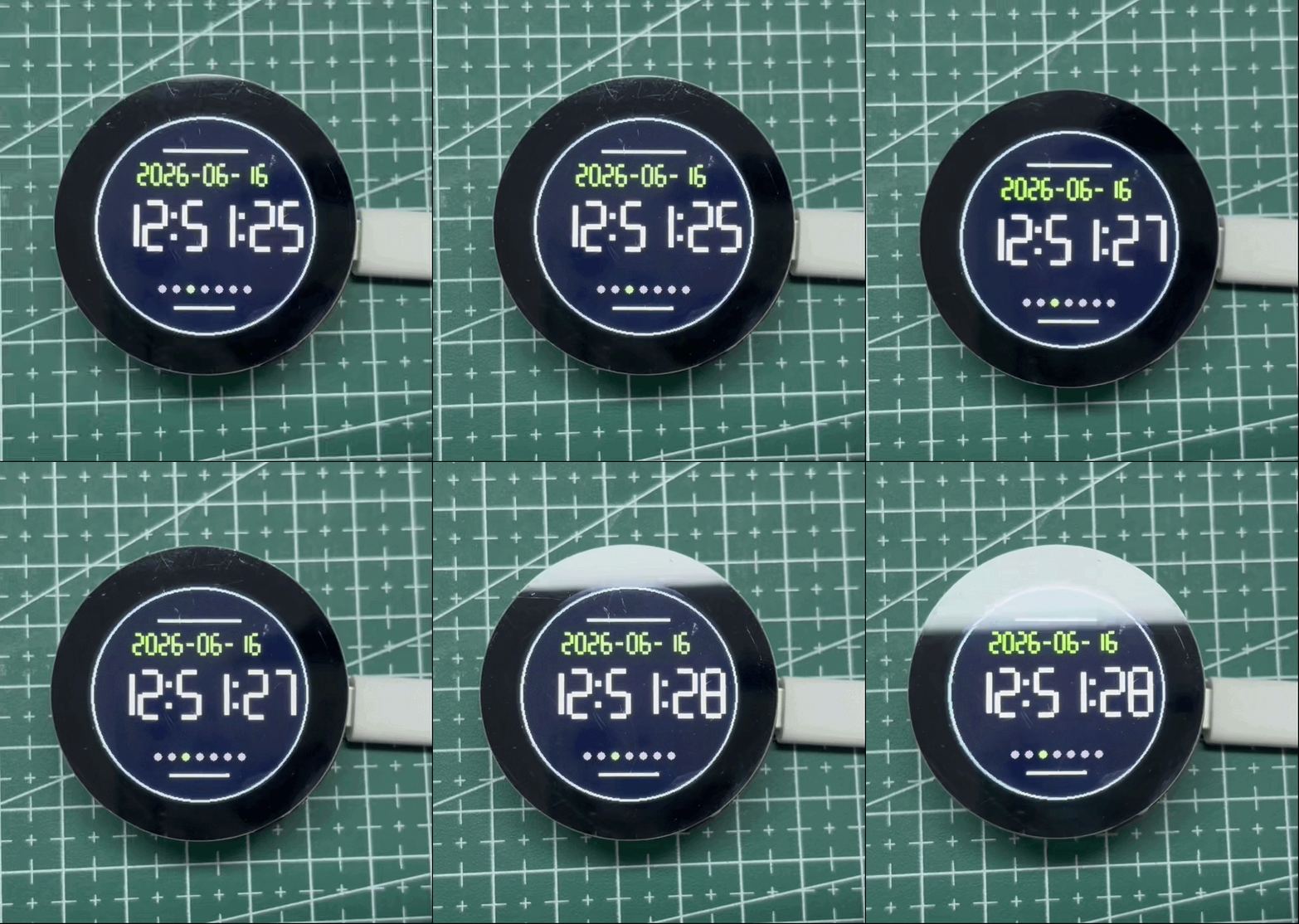
本示例通过 I²C 在圆形显示屏上的 PCF8563 RTC 上设置并读取日期和时间,并将结果显示在圆形 LCD 上。如果没有 RTC 备用电池,PCF8563 会在系统上电时保持计时,但在断电后不保证时间能够保留。安装 CR927 纽扣电池后,RTC 可以在主电源断开时继续运行,并在系统再次上电时保留正确时间。 如果 RTC 中不包含有效时间,本示例会将其初始化为 2026-06-16 12:00:00 以便演示。请单独将 RTC 设置为当前时间;本示例不会自动与当前时间同步。
技术支持与产品讨论
感谢您选择我们的产品!我们将为您提供多种支持,确保您在使用我们产品的过程中尽可能顺畅。我们提供多种沟通渠道,以满足不同的偏好和需求。