DM_Gripper – Open-Source Assembly Guide
The DM_Gripper is an open-source, 3D-printed robotic gripper designed around the DM-4310-2EC motor. Its modular design emphasizes ease of assembly and disassembly, enabling both hobbyists and robotics developers to rapidly prototype, customize, and scale their projects.
Fully compatible with DAMIAO actuators, the DM_Gripper also provides flexibility for integration with other actuator brands. Its unique swappable claw system allows users to quickly exchange claws of different shapes, supporting diverse robotic tasks and use cases.
All gripper parts are fully 3D-printable with minimal support requirements, making it accessible for makers, researchers, and engineers alike.
This wiki includes:
- Mechanism design overview
- Full bill of materials (BOM)
- 3D printing guide and setup
- Step-by-step assembly instructions
- Demo and practical use cases
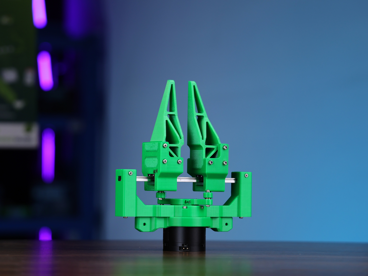
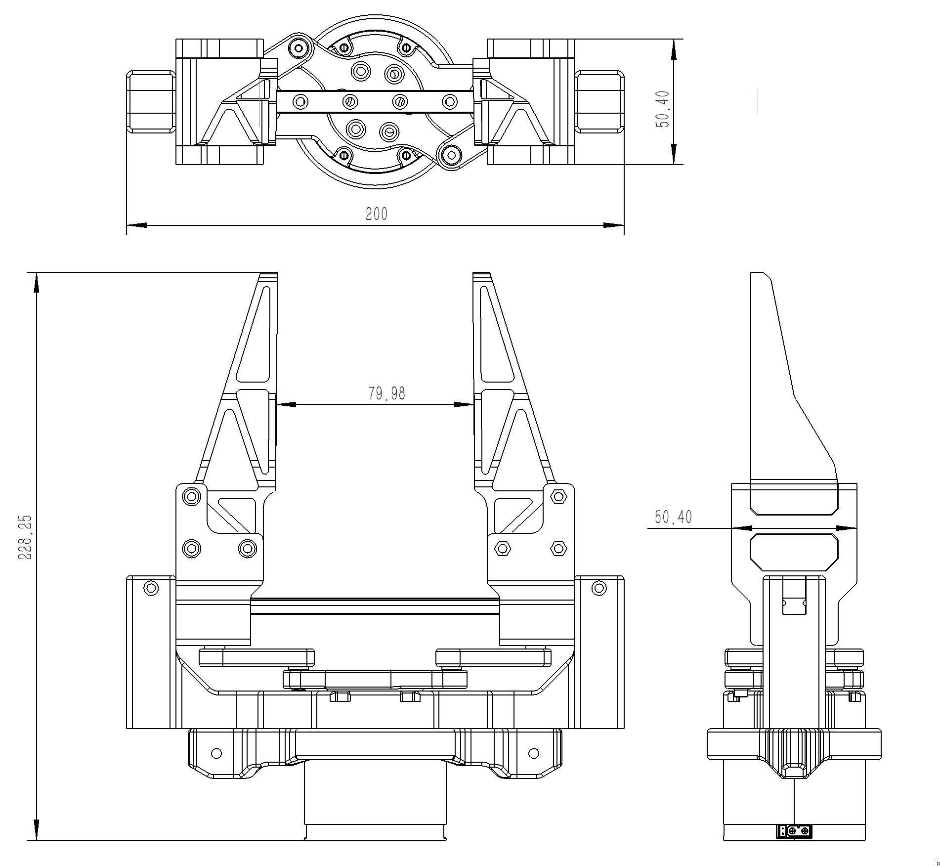
Dimensions/Operating Range
The dimensions and operating range are shown below in millimeters, with variable height depending on the claws used.
Drive Mechanisms
This gripper features a classical Dual Crank & Slider mechanism, translating rotational to axial motion.
- Crank & Slider Showcase:

- Motion Simulation Showcase
BOM
🔩 Fasteners
| Name | Quantity |
|---|---|
| Phillips Pan Head Screw PM3×8 | 8 |
| Hex Socket Cap Screw M3×20 | 4 |
| Hex Socket Cap Screw M3×25 | 6 |
| Hex Socket Cap Screw M3×50 | 8 |
| Hex Socket Cap Screw M3×16 | 12 |
| 304 Nylon Locking Hex Self-Locking Nut M3 (Thickness-3.9mm × Width-5.5mm) | 18 |
| Spring Washer – M3 | 4 |
| Flat Washer – M3×7mm (OD) × 0.5mm (Thickness) | 8 |
⚙️ Bearing
| Name | Quantity |
|---|---|
| F3-8M Miniature Thrust Bearing (ID-3mm × OD-8mm × Thickness-3.5mm) | 4 |
🛠️ Linear Motion
| Name | Quantity |
|---|---|
| Stainless Steel Linear Rail MGN9, 200 mm | 1 |
| Linear Rail Carriage MGN9C (Standard) | 2 |
🔌 Actuator
| Name | Quantity |
|---|---|
| DM4310-2EC Motor | 1 |
🧩 Custom Printables
| Name | Quantity |
|---|---|
| 3D Printed Parts | 1 set |
Assembly Guide
3D-Printing Guide
-
If you have dedicated support material or PETG+PLA in your AMS and want the best surface finish on supported faces, please refer to This Wiki.
Note: your print job may take longer. -
If you only have one filament to print, make sure you print with the correct orientations and decide whether you need the following steps (Turn On ADVANCED in Bambu Studio).
warningDo not change the Top Z distance if you are using PETG or ABS. Keep them as default. Only change this if you use PLA.
-
Step 1: Print layout with minimal supports required

-
Step 2: Scarf Settings provide a better surface finish as marked in Green Rectangles.

-
Step 3: My Print Settings: 0.2mm layer height, 25% infill density, Style – 3D Honeycomb.


-
Step By Step Assembly Walkthrough
- Step 1: Fix the Claw Holders to the MGN9C sliders with eight M3×8 mushroom-headed screws
- Step 2: Stack the bearings, rotors, and linkages ("hamburger" style)
- Step 3: Place eight M7 washers above and below the slots
- Step 4: Place four nuts above and below the washers
- Step 5: Screw four pairs of M3×20 screws and spring washers to the nuts (use pliers if necessary)
- Step 6: Place the Base and Actuator in position; the patterns on the rotor plate and actuator should align
- Step 7: Screw six M3×16 screws to secure the rotor plate to the actuator
- Step 8: Push the claw base to the maximum range for the next steps
- Step 9: Attach the cam holder to the bottom
- Step 10: Fix the cam holder with four pairs of M3×25 screws and nuts
- Step 11: Fix the base with six M3×16 screws (Pull out the rail for this stage and slide it back in afterwards)
- Step 12: Use two pairs of M3×50 screws and nuts to lock the rail on the base
- Step 13: Slide the rail presser in and secure with two pairs of M3×25 screws and nuts
- Step 14: Place the claws on the claw holders, and secure them with six pairs of M3×50 screws and nuts
Demos and CAD Files
- Follow the Damiao Actuators Wiki to get everything set up if you haven't done so.
- Follow the Torque Controller Demo (many thanks to tianrking) to get the gripper moving with a cool GUI.

- The CAD resources: editable STEP files and STLs are available here.