Driving reTerminal D1001 Audio Peripherals

Introduction
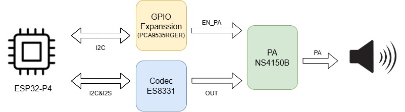
This guide introduces how to drive the I2S audio peripheral on the reTerminal D1001 development board. The system architecture involves three core components:
- ESP32-P4: The main processor that manages the audio data stream and controls peripheral configurations.
- ES8311: A low-power mono audio codec responsible for converting digital I2S data into analog audio signals.
- PCA9535: An I2C IO expander used to control the power amplifier's enable state, providing flexible GPIO expansion for peripheral control.
Audio Architecture Block Diagram
The audio system utilizes a dual-bus architecture: the I2S bus is dedicated to high-speed digital audio data transmission, while the I2C bus handles low-speed control commands for both the codec and the IO expander.
Pin Assignment and Principles
ESP32-P4 & ES8311 (Audio Data & Control)
| Signal Name | ESP32-P4 Pin | Function Description |
|---|---|---|
| I2C_SDA | GPIO20 | Serial Data: Carries configuration commands (volume, sample rate) to the ES8311. |
| I2C_SCL | GPIO21 | Serial Clock: Synchronizes I2C data transfers. |
| I2S_MCK | GPIO33 | Master Clock: High-frequency reference clock for the codec's internal delta-sigma modulators. |
| I2S_BCK | GPIO32 | Bit Clock: Synchronizes each individual bit of the audio data stream. |
| I2S_WS | GPIO31 | Word Select: Also known as LRCK, it defines the start of a new audio frame and selects Left/Right channels. |
| I2S_DO | GPIO30 | Data Output: Transmits the digital PCM audio data from the ESP32-P4 to the codec. |
| I2S_DI | GPIO11 | Data Input: Reserved for potential audio recording or loopback from the codec. |
ESP32-P4 & PCA9535RGER (GPIO Expansion)
| Signal Name | ESP32-P4 Pin | Function Description |
|---|---|---|
| I2C_SDA | GPIO20 | Shared I2C data bus for controlling the PCA9535 IO expander. |
| I2C_SCL | GPIO21 | Shared I2C clock bus. |
| EN_PA | EXP_GPO11 | PA Enable: Maps to Pin P13 on the PCA9535. Setting this HIGH enables the external power amplifier. |
Software Flow
GitHub Example Repository
Download the official reTerminal D1001 repository from GitHub to get the source code and drivers.
Please navigate to the driver_examples/01_I2SCodec directory within the repository to find the specific source code and project files for this audio example.
Development Execution Sequence
Step 1. Initialize I2C IO Expander (PCA9535RGER)
The external power amplifier (PA) is controlled via the PCA9535 expander. Enabling the PA is crucial because, without it, no audible sound will reach the speakers even if the codec is functioning correctly.
static esp_err_t pca9535_write_reg(uint8_t reg, uint8_t data)
{
    uint8_t write_buf[2] = {reg, data};
    return i2c_master_write_to_device(1, PCA9535_I2C_ADDR, write_buf, sizeof(write_buf), 1000 / portTICK_PERIOD_MS);
}

static void pca9535_init(void)
{
    int i2c_master_port = 1; // Use I2C_NUM_1
    i2c_config_t conf = {
        .mode = I2C_MODE_MASTER,
        .sda_io_num = MISC_I2C_SDA,
        .sda_pullup_en = GPIO_PULLUP_ENABLE,
        .scl_io_num = MISC_I2C_SCL,
        .scl_pullup_en = GPIO_PULLUP_ENABLE,
        .master.clk_speed = 100000,
    };
    i2c_param_config(i2c_master_port, &conf);
    i2c_driver_install(i2c_master_port, conf.mode, 0, 0, 0);

    // Configure Port 0 and Port 1 as output mode (0 = output, 1 = input)
    pca9535_write_reg(0x06, 0x00);
    pca9535_write_reg(0x07, 0x00);

    // Set P13 to HIGH to enable the Power Amplifier
    pca9535_write_reg(0x02, 0x00);
    pca9535_write_reg(0x03, 0x08);

    ESP_LOGI(TAG, "PCA9535 initialized, P13 set to HIGH");
}
Step 2. Configure I2S Driver
I2S is a synchronous serial communication protocol used specifically for transmitting digital audio. We configure the ESP32-P4 as the I2S Master, meaning it provides the BCLK and WS clocks to the codec.
static esp_err_t i2s_driver_init(void)
{
    i2s_chan_config_t chan_cfg = I2S_CHANNEL_DEFAULT_CONFIG(I2S_NUM, I2S_ROLE_MASTER);
    chan_cfg.auto_clear = true; // Prevents playing stale data from the buffer
    ESP_ERROR_CHECK(i2s_new_channel(&chan_cfg, &tx_handle, &rx_handle));
    i2s_std_config_t std_cfg = {
        .clk_cfg = I2S_STD_CLK_DEFAULT_CONFIG(EXAMPLE_SAMPLE_RATE),
        .slot_cfg = I2S_STD_PHILIPS_SLOT_DEFAULT_CONFIG(I2S_DATA_BIT_WIDTH_16BIT, I2S_SLOT_MODE_STEREO),
        .gpio_cfg = {
            .mclk = I2S_MCK_IO,
            .bclk = I2S_BCK_IO,
            .ws = I2S_WS_IO,
            .dout = I2S_DO_IO,
            .din = I2S_DI_IO,
            .invert_flags = {
                .mclk_inv = false,
                .bclk_inv = false,
                .ws_inv = false,
            },
        },
    };
    std_cfg.clk_cfg.mclk_multiple = EXAMPLE_MCLK_MULTIPLE;

    ESP_ERROR_CHECK(i2s_channel_init_std_mode(tx_handle, &std_cfg));
    ESP_ERROR_CHECK(i2s_channel_init_std_mode(rx_handle, &std_cfg));
    ESP_ERROR_CHECK(i2s_channel_enable(tx_handle));
    ESP_ERROR_CHECK(i2s_channel_enable(rx_handle));
    return ESP_OK;
}
Step 3. Initialize ES8311 Codec
The ES8311 must be configured to match the I2S settings (sample rate, data width) defined in the ESP32-P4. This is done via the I2C bus. Before building the project, you can customize the audio behavior by modifying the macros in main/example_config.h:
| Macro | Description | Setting Principles |
|---|---|---|
| EXAMPLE_SAMPLE_RATE | Audio Sample Rate (Hz) | Defines the frequency of audio samples. Common values are 16000 (voice) or 44100/48000 (music). |
| EXAMPLE_MCLK_MULTIPLE | MCLK to LRCLK Ratio | The Master Clock (MCLK) must be a multiple of the sample rate. 256 is standard for 16-bit, but 384 is often used for higher precision. |
| EXAMPLE_VOICE_VOLUME | Playback Volume | Ranges from 0 to 100. Sets the initial output level of the ES8311 codec. |
| EXAMPLE_MIC_GAIN | Microphone Gain (dB) | Adjusts the sensitivity of the dual microphones. Higher values increase volume but may introduce noise. |
| EXAMPLE_RECV_BUF_SIZE | DMA Buffer Size | Controls the size of the data chunks processed by DMA. Larger buffers prevent stutters but increase audio latency. |
static esp_err_t es8311_codec_init(void)
{
    const i2c_config_t es_i2c_cfg = {
        .sda_io_num = I2C_SDA_IO,
        .scl_io_num = I2C_SCL_IO,
        .mode = I2C_MODE_MASTER,
        .sda_pullup_en = GPIO_PULLUP_ENABLE,
        .scl_pullup_en = GPIO_PULLUP_ENABLE,
        .master.clk_speed = 100000,
    };
    i2c_param_config(I2C_NUM, &es_i2c_cfg);
    i2c_driver_install(I2C_NUM, I2C_MODE_MASTER,  0, 0, 0);

    es8311_handle_t es_handle = es8311_create(I2C_NUM, ES8311_ADDRRES_0);
    const es8311_clock_config_t es_clk = {
        .mclk_inverted = false,
        .sclk_inverted = false,
        .mclk_from_mclk_pin = true,
        .mclk_frequency = EXAMPLE_MCLK_FREQ_HZ,
        .sample_frequency = EXAMPLE_SAMPLE_RATE
    };

    es8311_init(es_handle, &es_clk, ES8311_RESOLUTION_16, ES8311_RESOLUTION_16);
    es8311_sample_frequency_config(es_handle, EXAMPLE_SAMPLE_RATE * EXAMPLE_MCLK_MULTIPLE, EXAMPLE_SAMPLE_RATE);
    es8311_voice_volume_set(es_handle, EXAMPLE_VOICE_VOLUME, NULL);
    es8311_microphone_config(es_handle, false);
    return ESP_OK;
}
Step 4. Main Entry and Task Creation
The main application initializes the peripherals and then hands off the playback logic to a dedicated FreeRTOS task.
void app_main(void)
{
    pca9535_init();

    if (i2s_driver_init() != ESP_OK) {
        ESP_LOGE(TAG, "i2s driver init failed");
        abort();
    }

    if (es8311_codec_init() != ESP_OK) {
        ESP_LOGE(TAG, "es8311 codec init failed");
        abort();
    }

    xTaskCreate(i2s_music, "i2s_music", 4096, NULL, 5, NULL);
}
Step 5. DMA Preloading and Data Playback
DMA (Direct Memory Access) allows the I2S peripheral to fetch data directly from memory without CPU intervention. Preloading the DMA buffer is a critical technique to prevent the "popping" noise that occurs when the I2S hardware starts with an empty buffer, causing a sudden DC offset change.
static void i2s_music(void *args)
{
    esp_err_t ret = ESP_OK;
    size_t bytes_write = 0;
    uint8_t *data_ptr = (uint8_t *)music_pcm_start;

    // Preload data to avoid initial "pop" sound
    ESP_ERROR_CHECK(i2s_channel_disable(tx_handle));
    ESP_ERROR_CHECK(i2s_channel_preload_data(tx_handle, data_ptr, music_pcm_end - data_ptr, &bytes_write));
    data_ptr += bytes_write;

    ESP_ERROR_CHECK(i2s_channel_enable(tx_handle));
    while (1) {
        ret = i2s_channel_write(tx_handle, data_ptr, music_pcm_end - data_ptr, &bytes_write, portMAX_DELAY);
        if (ret != ESP_OK) {
            ESP_LOGE(TAG, "[music] i2s write failed");
            abort();
        }
        data_ptr = (uint8_t *)music_pcm_start; // Loop playback
        vTaskDelay(1000 / portTICK_PERIOD_MS);
    }
}
Troubleshooting
Q1: No Sound Output from the Speaker
- Check: Verify if the power amplifier (PA) is enabled. The
EN_PAsignal is controlled via the PCA9535 IO expander on pin P13. Ensurepca9535_init()is called and correctly sets the output register (Port 1, Bit 3). - Check: Confirm the I2S connections and ensure the
i2s_channel_enable()function is called for the TX channel.
Q2: Audio is Distorted or Contains Crackling Noise
- Check: Ensure the I2S clock configuration (MCLK, BCLK, WS) matches the sample rate of your audio file. A mismatch in
EXAMPLE_SAMPLE_RATEcan cause pitch and speed issues. - Check: Verify that DMA preloading is implemented as shown in Step 5. Preloading prevents the "popping" sound caused by starting a channel with an empty buffer.
Q3: I2C Communication Failure with ES8311 or PCA9535
- Check: Verify the I2C SDA (GPIO20) and SCL (GPIO21) connections. Ensure no other peripheral is conflicting with these pins.
- Check: Confirm the I2C addresses are correct: 0x20 for PCA9535 and 0x18 for ES8311.