Driving reTerminal D1001 Microphone
Introduction
This wiki shows how to drive the I2S microphone on reTerminal D1001, and how to build a full record-and-play loop:
- Record from microphone for 10 seconds (ES7210 capture path).
- Play back the recorded PCM data for 10 seconds (ES8311 speaker path).
- Repeat continuously to validate both RX and TX audio pipelines.
The audio path in this example includes three key parts:
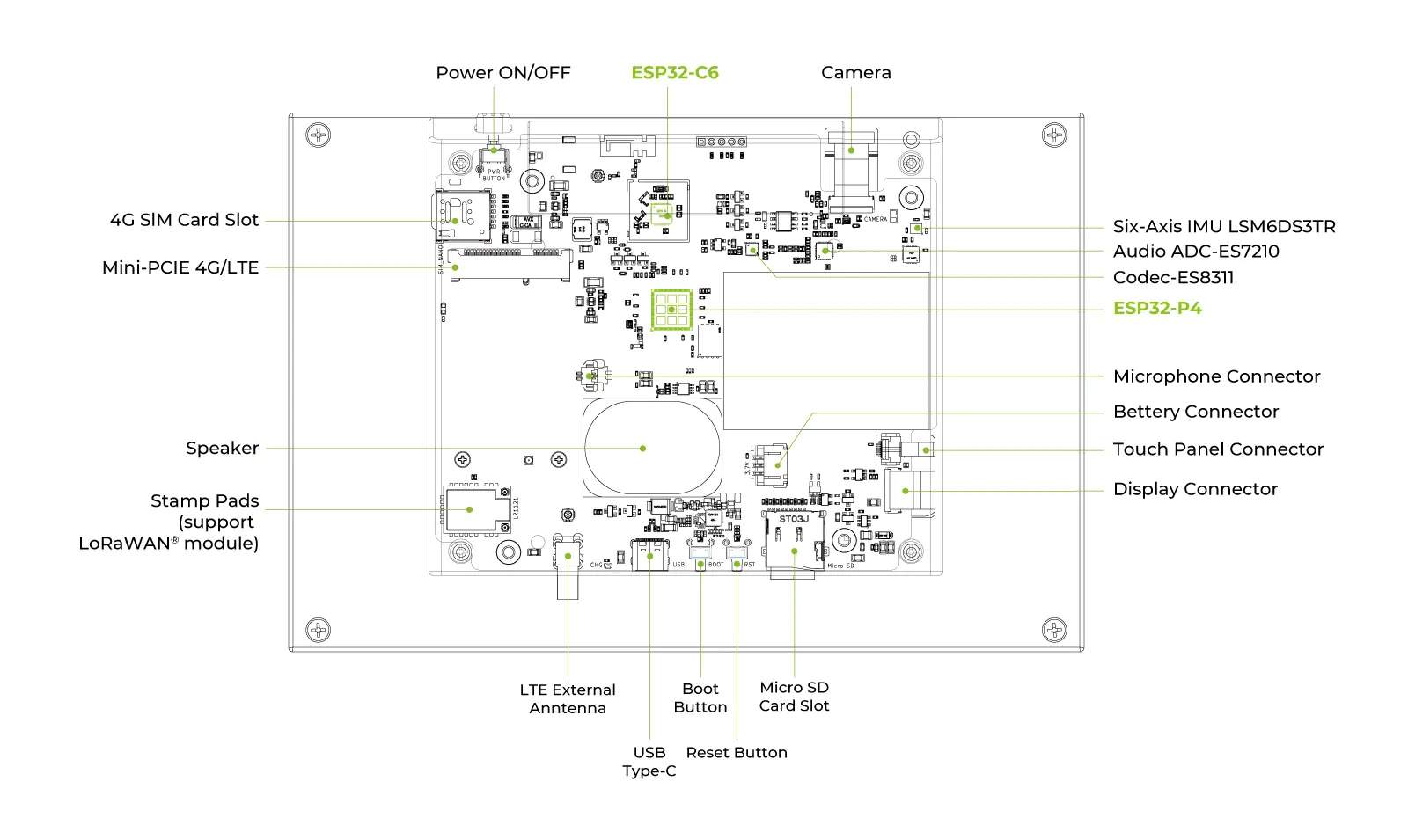
- ESP32-P4: Captures microphone PCM data and sends playback PCM data.
- ES7210 (I2C address:
0x40): Converts analog microphone signals into digital I2S data. - ES8311 + PA control (PCA9535): Converts PCM to speaker output and enables the power amplifier for playback.
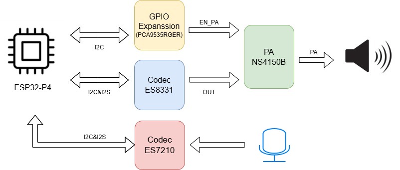
Microphone + Speaker Architecture
Block Diagram (ES7210 + ES8311)
Pin Mapping Table
| Signal Group | Signal Name | ESP32-P4 Pin | Connected Device | Description |
|---|---|---|---|---|
| Shared I2C Control | I2C_SDA | GPIO20 | ES7210 / PCA9535 | Shared I2C data line for ES7210 configuration and PA control |
| Shared I2C Control | I2C_SCL | GPIO21 | ES7210 / PCA9535 | Shared I2C clock line |
| Microphone I2S (RX) | ADC_I2S_MCLK | GPIO29 | ES7210 | Master clock for ES7210 |
| Microphone I2S (RX) | ADC_I2S_SCLK | GPIO28 | ES7210 | Bit clock for ES7210 capture path |
| Microphone I2S (RX) | ADC_I2S_LRCK | GPIO27 | ES7210 | Word select (LRCK) |
| Microphone I2S (RX) | ADC_I2S_SDOUT | GPIO26 | ES7210 | PCM data output from ES7210 to ESP32-P4 |
| PA Control | EN_PA (EXP_GPO11) | PCA9535 P13 | Power Amplifier | Keep HIGH when validating microphone + speaker loop playback |
This table focuses on the microphone path. In this example, ES8311 also shares the same I2C bus for playback codec configuration.
Software Flow
GitHub Example Repository
Download the official reTerminal D1001 repository from GitHub:
Project Directory Structure
The following diagram shows the project directory structure used in this example.
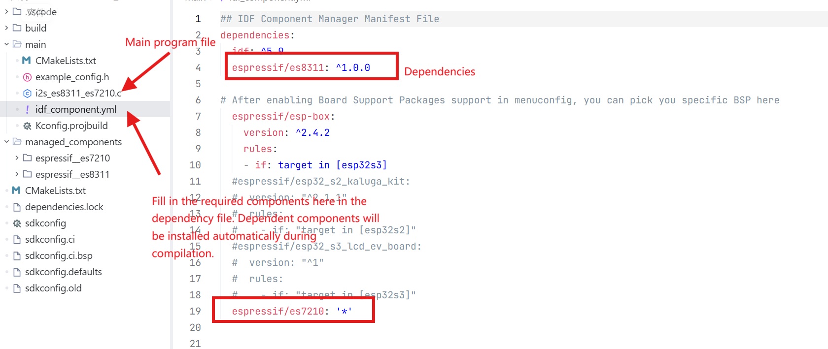
Please navigate to the record-and-play example directory for ES7210 + ES8311 in the repository (for example, driver_examples/02_I2SCodec_es7210).
Development Execution Sequence
Step 1. Initialize PA Control via PCA9535
The speaker path requires the PA enable pin to be asserted through PCA9535 (P13 = HIGH).
static esp_err_t pca9535_write_reg(uint8_t reg, uint8_t data)
{
    uint8_t write_buf[2] = {reg, data};
    return i2c_master_write_to_device(1, PCA9535_I2C_ADDR, write_buf, sizeof(write_buf), 1000 / portTICK_PERIOD_MS);
}

static void pca9535_init(void)
{
    int i2c_master_port = 1; // Use I2C_NUM_1
    i2c_config_t conf = {
        .mode = I2C_MODE_MASTER,
        .sda_io_num = MISC_I2C_SDA,
        .sda_pullup_en = GPIO_PULLUP_ENABLE,
        .scl_io_num = MISC_I2C_SCL,
        .scl_pullup_en = GPIO_PULLUP_ENABLE,
        .master.clk_speed = 100000,
    };
    i2c_param_config(i2c_master_port, &conf);
    i2c_driver_install(i2c_master_port, conf.mode, 0, 0, 0);

    pca9535_write_reg(0x06, 0x00);
    pca9535_write_reg(0x07, 0x00);
    pca9535_write_reg(0x02, 0x00);
    pca9535_write_reg(0x03, 0x08); // Set P13 (EXP_GPO11) to HIGH
}
Step 2. Initialize I2S for ES8311 (Speaker TX)
Configure one I2S TX channel for playback to ES8311.
static esp_err_t i2s_driver_init_es8311(void)
{
    i2s_chan_config_t tx_chan_cfg = I2S_CHANNEL_DEFAULT_CONFIG(I2S_NUM, I2S_ROLE_MASTER);
    tx_chan_cfg.auto_clear = true;
    ESP_ERROR_CHECK(i2s_new_channel(&tx_chan_cfg, &tx_handle_es8311, NULL));

    i2s_std_config_t std_cfg = {
        .clk_cfg = I2S_STD_CLK_DEFAULT_CONFIG(EXAMPLE_SAMPLE_RATE),
        .slot_cfg = I2S_STD_PHILIPS_SLOT_DEFAULT_CONFIG(I2S_DATA_BIT_WIDTH_16BIT, I2S_SLOT_MODE_STEREO),
        .gpio_cfg = {
            .mclk = I2S_MCK_IO,
            .bclk = I2S_BCK_IO,
            .ws = I2S_WS_IO,
            .dout = I2S_DO_IO,
            .din = I2S_GPIO_UNUSED,
        },
    };
    std_cfg.clk_cfg.mclk_multiple = EXAMPLE_MCLK_MULTIPLE;

    ESP_ERROR_CHECK(i2s_channel_init_std_mode(tx_handle_es8311, &std_cfg));
    ESP_ERROR_CHECK(i2s_channel_enable(tx_handle_es8311));
    ESP_LOGI(TAG, "ES8311 I2S initialized");
    return ESP_OK;
}
Step 3. Initialize ES8311 Codec
ES8311 is configured for speaker playback format and volume.
static esp_err_t es8311_codec_init(void)
{
    const i2c_config_t es_i2c_cfg = {
        .sda_io_num = I2C_SDA_IO,
        .scl_io_num = I2C_SCL_IO,
        .mode = I2C_MODE_MASTER,
        .sda_pullup_en = GPIO_PULLUP_ENABLE,
        .scl_pullup_en = GPIO_PULLUP_ENABLE,
        .master.clk_speed = 100000,
    };
    i2c_param_config(I2C_NUM, &es_i2c_cfg);
    i2c_driver_install(I2C_NUM, I2C_MODE_MASTER, 0, 0, 0);

    es8311_handle_t es_handle = es8311_create(I2C_NUM, ES8311_ADDRRES_0);
    const es8311_clock_config_t es_clk = {
        .mclk_inverted = false,
        .sclk_inverted = false,
        .mclk_from_mclk_pin = true,
        .mclk_frequency = EXAMPLE_MCLK_FREQ_HZ,
        .sample_frequency = EXAMPLE_SAMPLE_RATE
    };

    ESP_ERROR_CHECK(es8311_init(es_handle, &es_clk, ES8311_RESOLUTION_16, ES8311_RESOLUTION_16));
    ESP_ERROR_CHECK(es8311_sample_frequency_config(es_handle, EXAMPLE_SAMPLE_RATE * EXAMPLE_MCLK_MULTIPLE, EXAMPLE_SAMPLE_RATE));
    ESP_ERROR_CHECK(es8311_voice_volume_set(es_handle, EXAMPLE_VOICE_VOLUME, NULL));
    ESP_ERROR_CHECK(es8311_microphone_config(es_handle, false));
    ESP_LOGI(TAG, "ES8311 codec configured");
    return ESP_OK;
}
Step 4. Initialize I2S + ES7210 (Microphone RX)
Set up microphone capture from ES7210 through I2S RX.
static esp_err_t i2s_driver_init_es7210(void)
{
    i2s_chan_config_t rx_chan_cfg = I2S_CHANNEL_DEFAULT_CONFIG(ES7210_I2S_NUM, I2S_ROLE_MASTER);
    ESP_ERROR_CHECK(i2s_new_channel(&rx_chan_cfg, NULL, &rx_handle_es7210));

    i2s_std_config_t std_cfg = {
        .clk_cfg = I2S_STD_CLK_DEFAULT_CONFIG(EXAMPLE_SAMPLE_RATE),
        .slot_cfg = I2S_STD_PHILIPS_SLOT_DEFAULT_CONFIG(I2S_DATA_BIT_WIDTH_16BIT, I2S_SLOT_MODE_STEREO),
        .gpio_cfg = {
            .mclk = ES7210_I2S_MCK_IO,
            .bclk = ES7210_I2S_BCK_IO,
            .ws = ES7210_I2S_WS_IO,
            .dout = I2S_GPIO_UNUSED,
            .din = ES7210_I2S_DI_IO,
        },
    };
    std_cfg.clk_cfg.mclk_multiple = EXAMPLE_MCLK_MULTIPLE;

    ESP_ERROR_CHECK(i2s_channel_init_std_mode(rx_handle_es7210, &std_cfg));
    ESP_ERROR_CHECK(i2s_channel_enable(rx_handle_es7210));
    ESP_LOGI(TAG, "ES7210 I2S initialized in STD mode (Stereo)");
    return ESP_OK;
}

static esp_err_t es7210_codec_init(void)
{
    es7210_dev_handle_t es7210_handle = NULL;
    es7210_i2c_config_t i2c_conf = {
        .i2c_port = I2C_NUM,
        .i2c_addr = ES7210_ADDRRES_00
    };
    ESP_ERROR_CHECK(es7210_new_codec(&i2c_conf, &es7210_handle));

    es7210_codec_config_t codec_conf = {
        .sample_rate_hz = EXAMPLE_SAMPLE_RATE,
        .mclk_ratio = EXAMPLE_MCLK_MULTIPLE,
        .i2s_format = ES7210_I2S_FMT_I2S,
        .bit_width = ES7210_I2S_BITS_16B,
        .mic_bias = ES7210_MIC_BIAS_2V87,
        .mic_gain = ES7210_MIC_GAIN_24DB,
        .flags.tdm_enable = false
    };
    ESP_ERROR_CHECK(es7210_config_codec(es7210_handle, &codec_conf));
    ESP_ERROR_CHECK(es7210_config_volume(es7210_handle, 0));
    ESP_LOGI(TAG, "ES7210 codec configured");
    return ESP_OK;
}
Step 5. Record 10s and Play 10s in a Loop
Allocate a PSRAM buffer, record by chunks from ES7210, then write the recorded PCM to ES8311.
static void record_play_task(void *args)
{
    int16_t *record_buf = heap_caps_malloc(RECORD_BUFFER_SIZE, MALLOC_CAP_SPIRAM | MALLOC_CAP_8BIT);
    if (!record_buf) {
        vTaskDelete(NULL);
        return;
    }

    size_t bytes_read = 0;
    size_t bytes_written = 0;

    while (1) {
        size_t total_read = 0;
        size_t chunk_size = 4096;

        // Record phase (10s)
        while (total_read < RECORD_BUFFER_SIZE) {
            size_t to_read = RECORD_BUFFER_SIZE - total_read;
            if (to_read > chunk_size) {
                to_read = chunk_size;
            }
            if (i2s_channel_read(rx_handle_es7210, (uint8_t *)record_buf + total_read, to_read, &bytes_read, portMAX_DELAY) == ESP_OK) {
                total_read += bytes_read;
            } else {
                break;
            }
        }

        // Playback phase (10s)
        size_t total_written = 0;
        while (total_written < total_read) {
            size_t to_write = total_read - total_written;
            if (to_write > chunk_size) {
                to_write = chunk_size;
            }
            if (i2s_channel_write(tx_handle_es8311, (uint8_t *)record_buf + total_written, to_write, &bytes_written, portMAX_DELAY) == ESP_OK) {
                total_written += bytes_written;
            } else {
                break;
            }
        }
    }
}
Step 6. Main Entry
Initialize all modules in order, then start the record-play task.
void app_main(void)
{
    printf("\n============================================\n");
    printf("   Record & Play Example (ES7210 + ES8311)  \n");
    printf("============================================\n\n");

    pca9535_init();

    if (i2s_driver_init_es8311() != ESP_OK) {
        abort();
    }
    if (es8311_codec_init() != ESP_OK) {
        abort();
    }
    if (i2s_driver_init_es7210() != ESP_OK) {
        abort();
    }
    if (es7210_codec_init() != ESP_OK) {
        abort();
    }

    xTaskCreatePinnedToCore(record_play_task, "record_play_task", 32768, NULL, 5, NULL, 0);
}
Expected Serial Log Before Recording
When using our example project, before the first 10-second recording starts, the serial monitor should print startup messages similar to:
Record & Play Example (ES7210 + ES8311)
PCA9535 initialized, P13 set to HIGH
ES8311 I2S initialized
ES8311 codec configured
ES7210 I2S initialized in STD mode (Stereo)
ES7210 codec configured
=== Start Recording for 10 seconds ===
If these logs do not appear in sequence, check each init step return value first.
Troubleshooting
Q1: No Sound During Playback
- Check: Confirm PCA9535 is initialized and P13 (
EN_PA) is set HIGH. - Check: Verify ES8311 TX I2S pins and
i2s_channel_enable(tx_handle_es8311)execution.
Q2: No Data Captured from Microphone
- Check: Verify ES7210 I2S RX pin mapping and
i2s_channel_enable(rx_handle_es7210)execution. - Check: Confirm ES7210 I2C address and codec init return value.
Q3: Distorted Audio or Loud Noise
- Check: Keep sample rate and MCLK ratio consistent across ES8311, ES7210, and I2S configs.
- Check: Reduce microphone gain (for example, lower than
ES7210_MIC_GAIN_24DB) if near-field clipping occurs. - Check: If speaker output has continuous metallic noise or incomplete voice, verify channel slot config:
slot_cfg = I2S_STD_PHILIPS_SLOT_DEFAULT_CONFIG(I2S_DATA_BIT_WIDTH_16BIT, I2S_SLOT_MODE_STEREO). - Check: Ensure RX/TX channel alignment is correct; mono/stereo mismatch can cause broken or robotic voice.