PlatformIO Cookbook: XIAO ePaper Driver Boards (EE0x)
Applicable to EE02 / EE03 / EE04 / EE05. Because all four boards share the same XIAO ESP32-S3 base and the same Seeed_GFX driver pipeline, the project setup, library list, and code patterns are identical; the only thing that changes between them is the BOARD_SCREEN_COMBO value you pick in the Configuration Tool for driver.h.
Worked example: EE04 + 7.5" 800×480 mono ePaper screen. Substitute your own board + screen pair in driver.h and the rest of the workflow (button GPIOs, battery ADC, dashboard UI, button-driven page switching) carries over.
This cookbook is specific to PlatformIO. If you'd rather use the Arduino IDE (the more common path for our ePaper line), see Work with Arduino for the platform-level guide, the reTerminal E Series — ePaper Display cookbook for display-rendering examples, and the reTerminal E Series — Onboard Peripherals cookbook for hardware-level examples (LED, buzzer, buttons, SHT4x, battery, microSD) that also apply to the EE0x boards.
PlatformIO Introduce
PlatformIO stands as a powerful and highly extensible development ecosystem designed for embedded systems. It seamlessly integrates support for a vast array of development boards and microcontrollers, offering unparalleled flexibility. What sets PlatformIO apart is its remarkable scalability: even if your specific board isn't natively supported, its architecture allows for straightforward custom board definitions.
Crucially, PlatformIO bridges the gap for developers familiar with Arduino, enabling the compilation and deployment of Arduino-style code by simply including the relevant libraries.
Hardware Preparation
You need to prepare a XIAO ePaper Display Board EE04 along with screens of the supported size.The 24-pin 800×480 7.5-inch ink screen used in this tutorial is an example.
| XIAO ePaper Display Board(ESP32-S3) - EE04 | 7.5" Monochrome eInk |
|---|---|
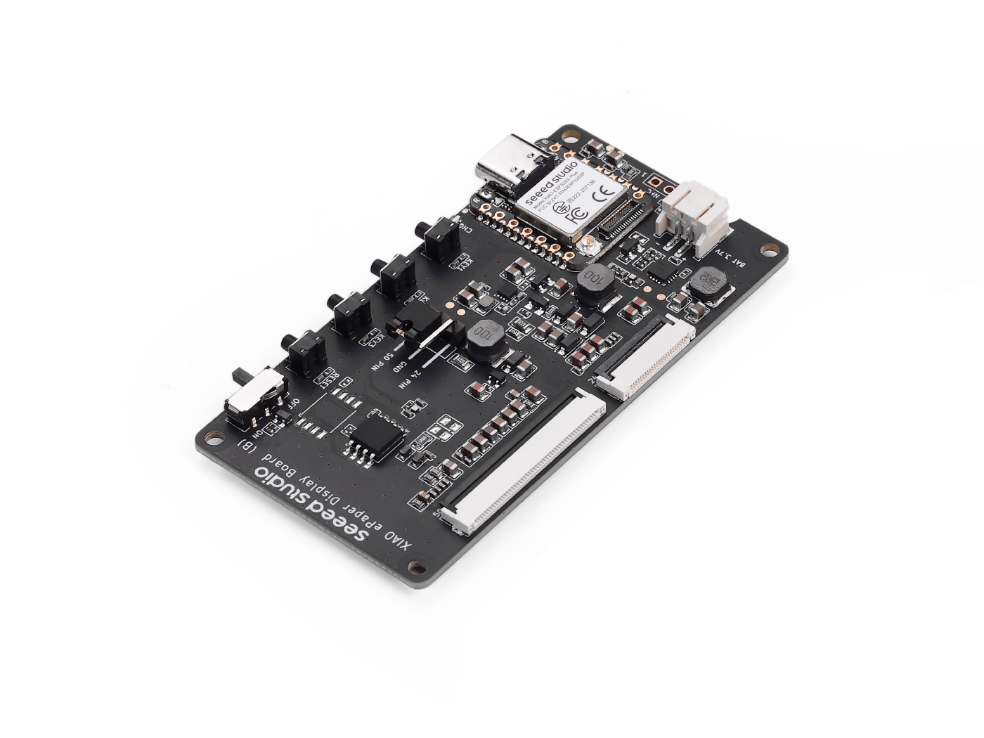 | 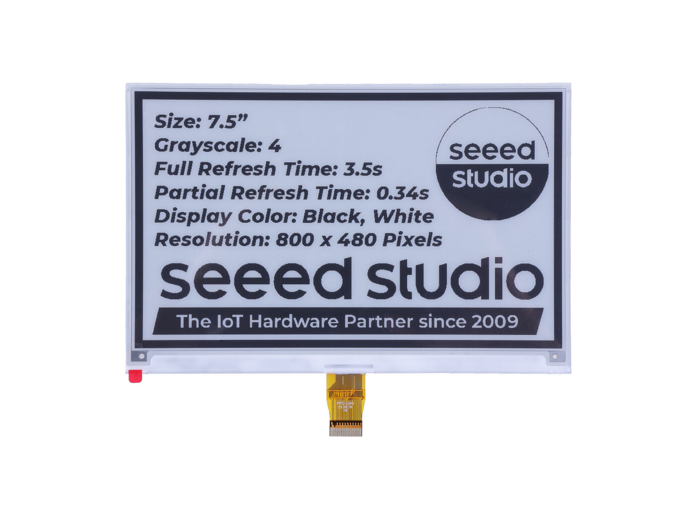 |
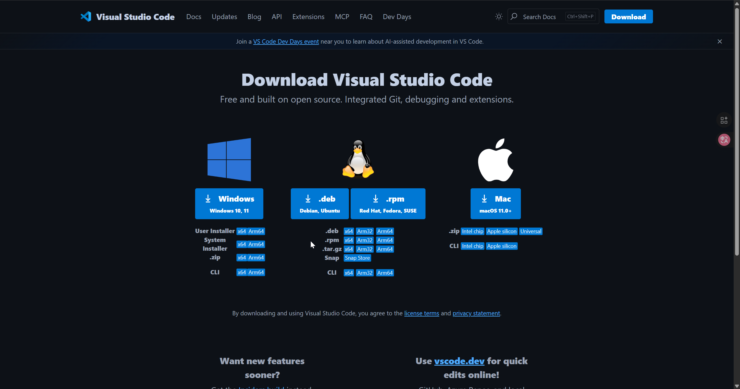
Download Vscode
Download according to the system you are using Vscode
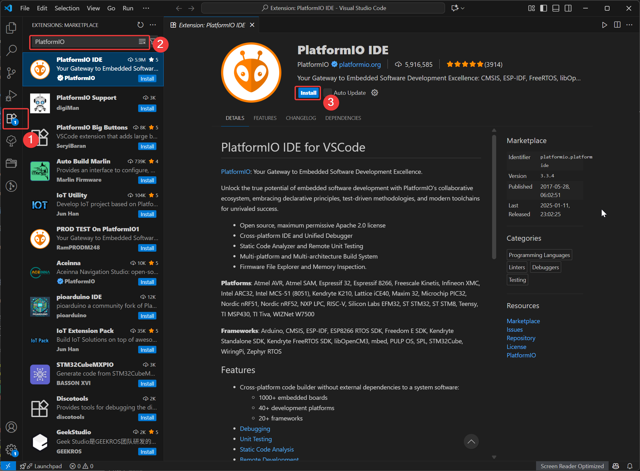
Install the PlatformIO
Open VSCode, click on Extensions, then search for PlatformIO and select to install. After the installation is complete, restart VSCode.
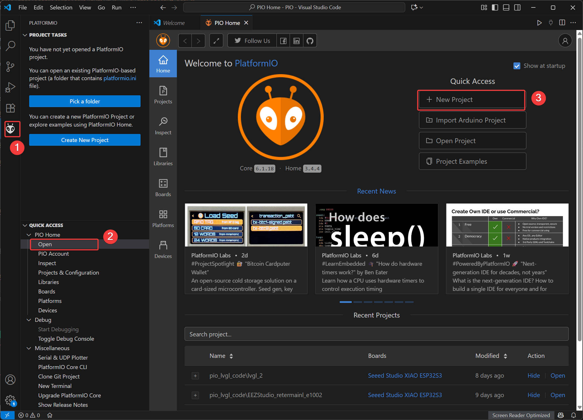
New Project
- Open the PIO Home interface and select
New Project
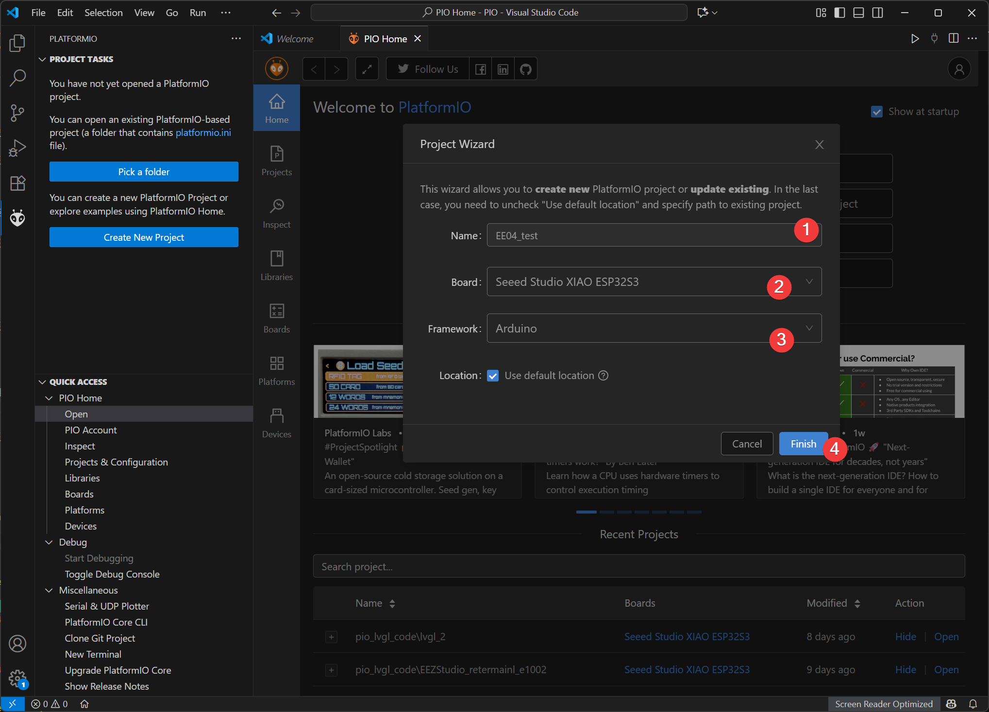
- Name: Name your project name
- Board: Select Seeed Studio XIAO ESP32S3
- Framework: Select Ardunio
- Location: The path of the engineering files can be set as a custom path or the default path can be selected.
- Click "Finish" and wait for the creation to be completed. Then, open the project file in the workspace.
Add the Seeed GFX library
This library has same function as TFT library and no compatible with it. If you have installed TFT library or other similary display libraries, please uninstall it first.
We'll use the Seeed_GFX library, which provides comprehensive support for various Seeed Studio display devices.
Step 1. Download the Seeed_GFX library from GitHub:
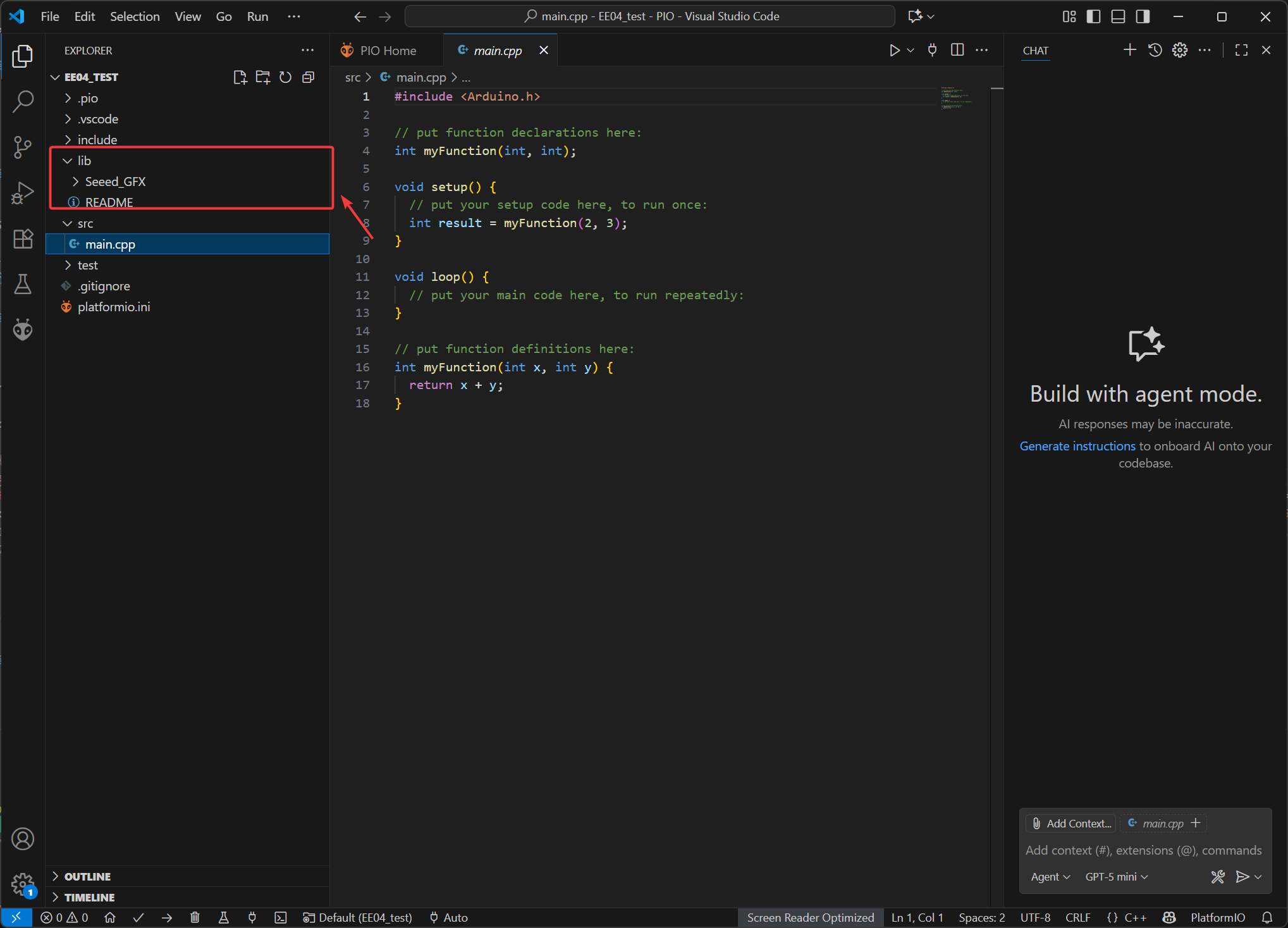
Step 2. Move the extracted files to the lib directory of the project files.
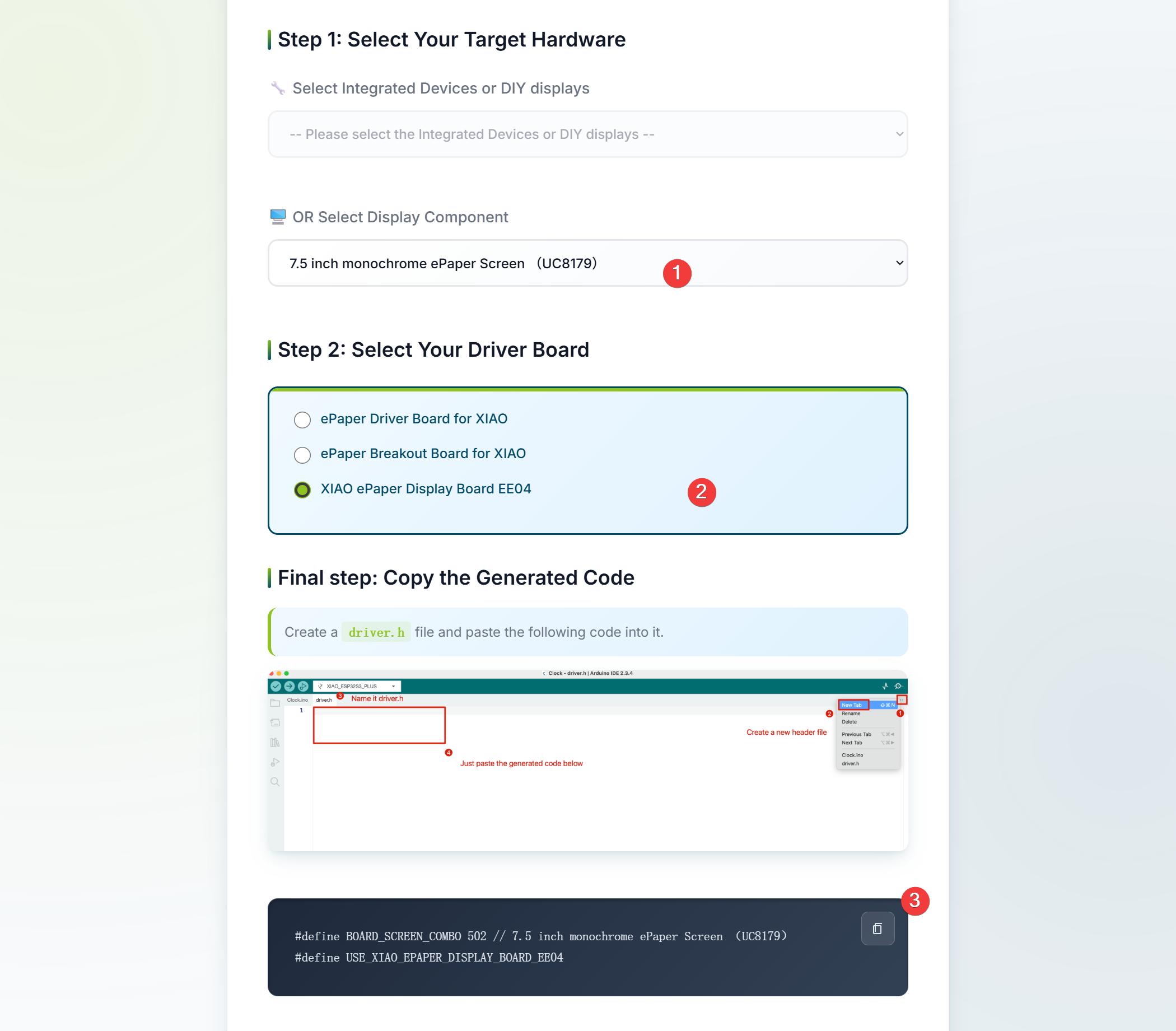
Step 3. Add driver.h file
- On the tool page, select the screen specification you are using. Here, the selected option is a 7.5-inch monochrome e-paper screen.
- Select the XIAO ePaper Display Board EE04 for the driver board, and then the corresponding driver code will be generated.
#define BOARD_SCREEN_COMBO 502 // 7.5 inch monochrome ePaper Screen (UC8179)
#define USE_XIAO_EPAPER_DISPLAY_BOARD_EE04
If you make the wrong choice, the screen will display nothing. So please make sure your devices or components type.
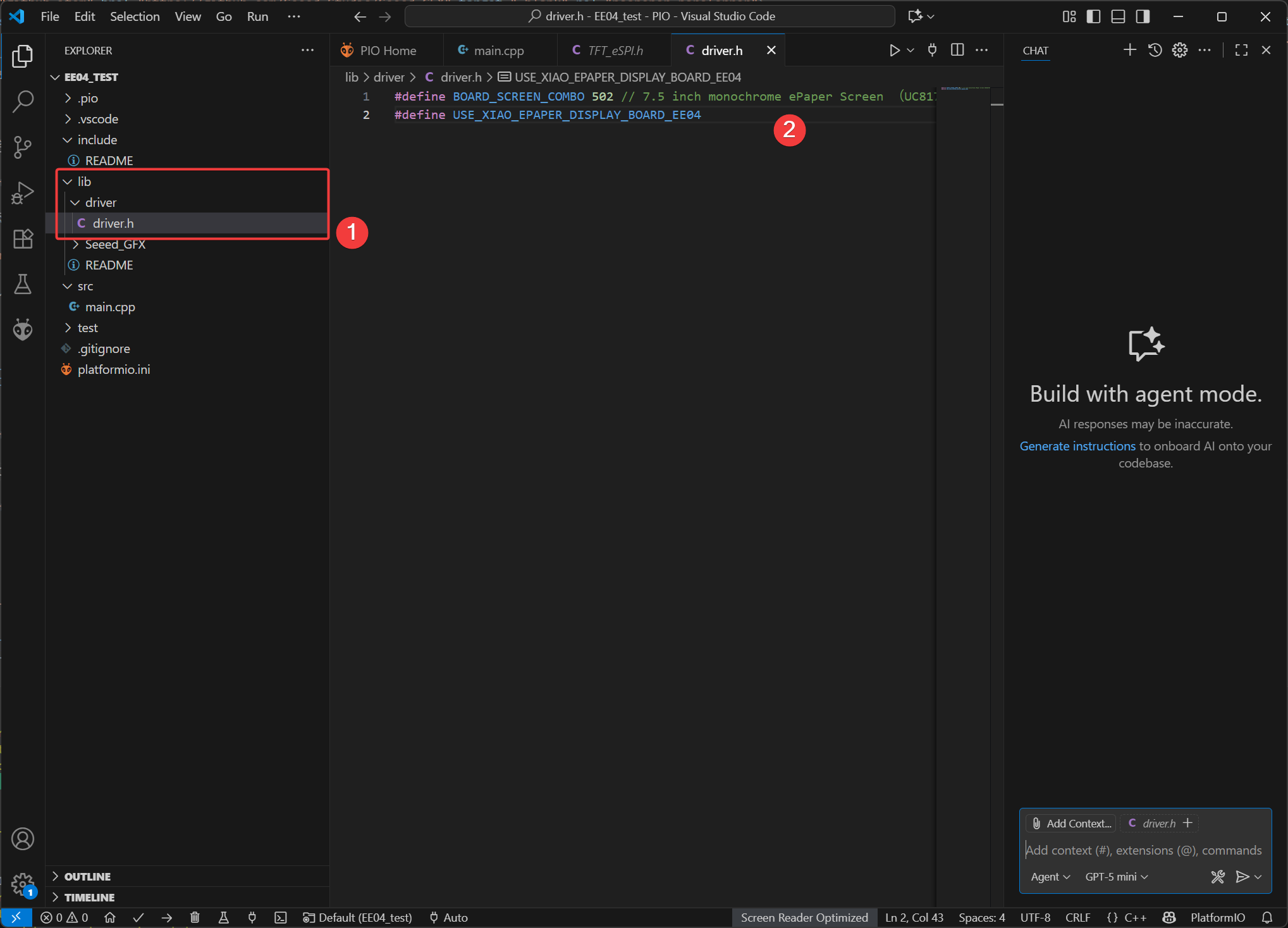
- Create a new
driverfolder under thelibdirectory of the PlatfromIO project file, then add thedriver.hfile. Copy the generated header file code and press Ctrl + S to save.
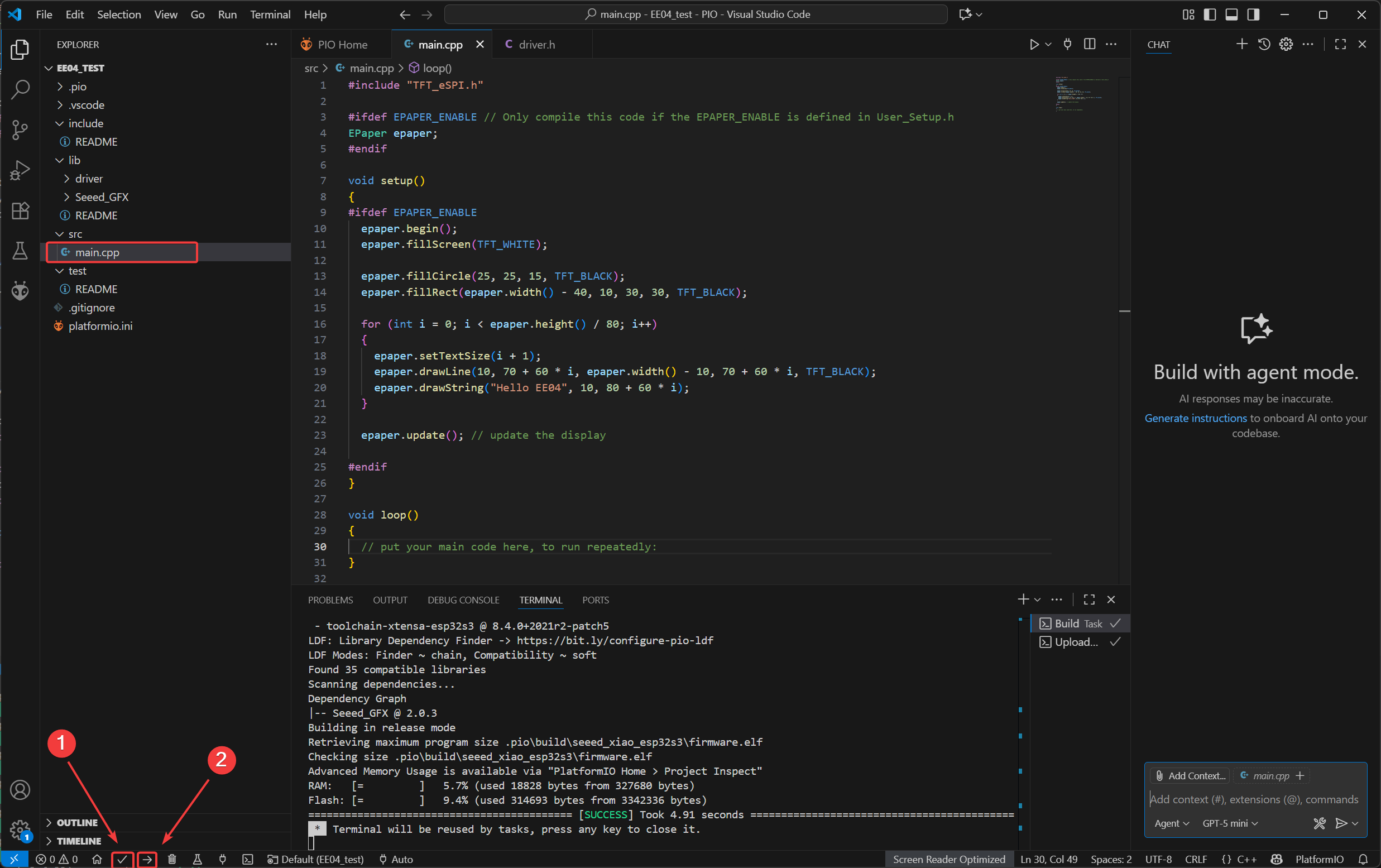
Upload
Copy the code to main.cpp, click Build, and after completion, upload.
#include "TFT_eSPI.h"

#ifdef EPAPER_ENABLE // Only compile this code if the EPAPER_ENABLE is defined in User_Setup.h
EPaper epaper;
#endif

void setup()
{
#ifdef EPAPER_ENABLE
    epaper.begin();
    epaper.fillScreen(TFT_WHITE);

    epaper.fillCircle(25, 25, 15, TFT_BLACK);
    epaper.fillRect(epaper.width() - 40,  10, 30, 30, TFT_BLACK);

    for (int i = 0; i < epaper.height() / 80; i++)
    {
        epaper.setTextSize(i + 1);
        epaper.drawLine(10, 70 + 60 * i, epaper.width() - 10, 70 + 60 * i, TFT_BLACK);
        epaper.drawString("Hello EE04", 10, 80 + 60 * i);
    }

    epaper.update(); // update the display

#endif
}

void loop()
{
    // put your main code here, to run repeatedly:
}
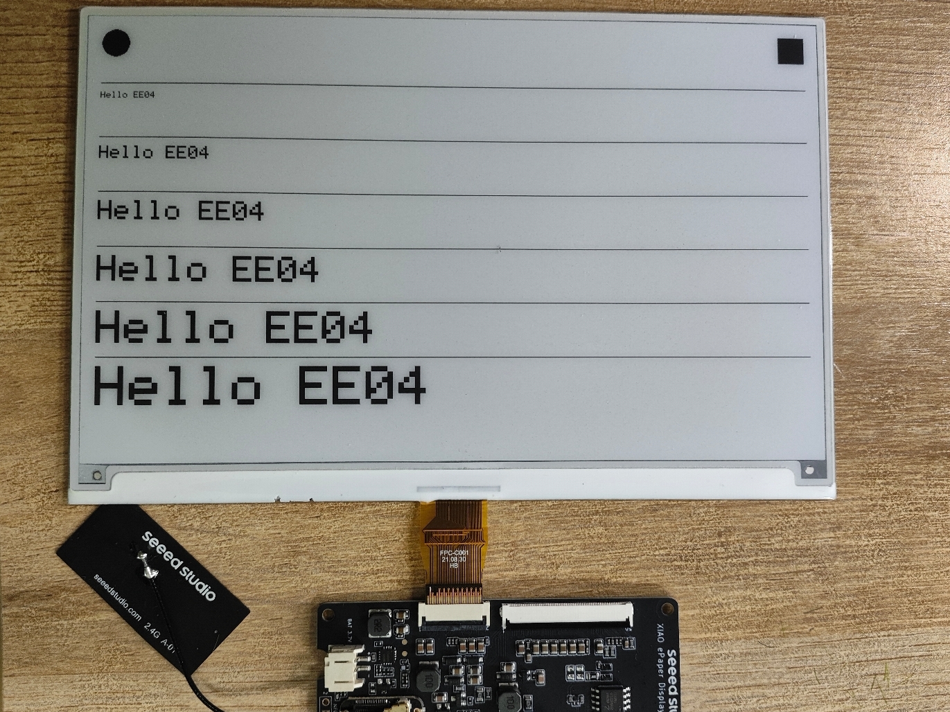
- Effect demonstration
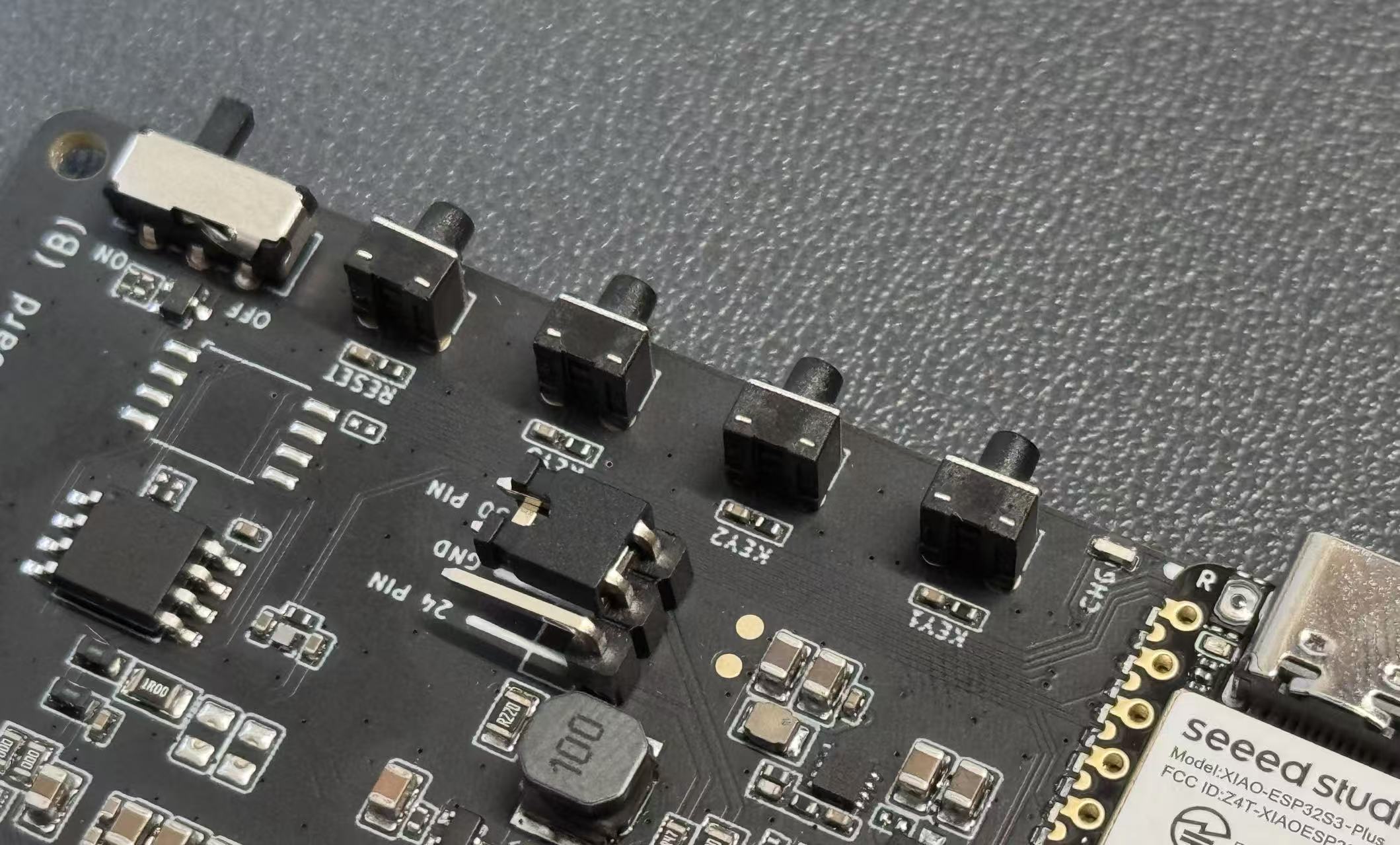
User button
he EE04 features three user-programmable buttons that can be used for various control purposes. This section demonstrates how to read button states and respond to button presses using Arduino.
On the EE04, the three buttons are connected to the ESP32-S3:
- KEY1 (GPIO2_D1/A1)
- KEY2 (GPIO3_D2/A2)
- KEY3 (GPIO5_D4/A4)
All buttons are active-low, meaning they read LOW when pressed and HIGH when released.
Basic Button Reading Example
This example demonstrates how to detect button presses and print messages to the serial monitor.
#include <Arduino.h>
// reTerminal E Series - Button Test
// Based on hardware schematic

// Define button pins according to schematic
const int BUTTON_KEY0 = 2;   // KEY0 - GPIO2
const int BUTTON_KEY1 = 3;   // KEY1 - GPIO3
const int BUTTON_KEY2 = 5;   // KEY2 - GPIO5

// Button state variables
bool lastKey0State = HIGH;
bool lastKey1State = HIGH;
bool lastKey2State = HIGH;

void setup() {
  // Initialize serial communication
  Serial.begin(115200);
  while (!Serial) {
    delay(10); // Wait for serial port to connect
  }

  Serial.println("=================================");
  Serial.println("Press any button to see output");
  Serial.println();

  // Configure button pins as inputs
  // Hardware already has pull-up resistors, so use INPUT mode
  pinMode(BUTTON_KEY0, INPUT_PULLUP);
  pinMode(BUTTON_KEY1, INPUT_PULLUP);
  pinMode(BUTTON_KEY2, INPUT_PULLUP);

  // Read initial states
  lastKey0State = digitalRead(BUTTON_KEY0);
  lastKey1State = digitalRead(BUTTON_KEY1);
  lastKey2State = digitalRead(BUTTON_KEY2);

  Serial.println("Setup complete. Ready to detect button presses...");
}

void loop() {
  // Read current button states
  bool key0State = digitalRead(BUTTON_KEY0);
  bool key1State = digitalRead(BUTTON_KEY1);
  bool key2State = digitalRead(BUTTON_KEY2);

  // Check KEY1
  if (key0State != lastKey0State) {
    if (key0State == LOW) {
      Serial.println("KEY0 (GPIO2) pressed!");
    } else {
      Serial.println("KEY0 (GPIO2) released!");
    }
    lastKey0State = key0State;
    delay(50); // Debounce delay
  }

  // Check KEY2
  if (key1State != lastKey1State) {
    if (key1State == LOW) {
      Serial.println("KEY1 (GPIO3) pressed!");
    } else {
      Serial.println("KEY1 (GPIO3) released!");
    }
    lastKey1State = key1State;
    delay(50); // Debounce delay
  }

  // Check KEY3
  if (key2State != lastKey2State) {
    if (key2State == LOW) {
      Serial.println("KEY2 (GPIO5) pressed!");
    } else {
      Serial.println("KEY2 (GPIO5) released!");
    }
    lastKey2State = key2State;
    delay(50); // Debounce delay
  }

  delay(10); // Small delay to prevent excessive CPU usage
}
Code Explanation:
- Core Function Analysis
-
pinMode(pin, mode)- Function: Configures the pin mode.
- The
INPUT_PULLUPmode is used here to enable the internal pull-up resistor. This makes the pin output a high level (HIGH) by default when the button is not pressed, and output a low level (LOW) when the button is pressed (as it connects to ground).
-
digitalRead(pin)- Function: Reads the level state (HIGH or LOW) of the specified pin.
- It is used in the loop to obtain the current state of the button in real time, which helps determine if the button has been activated.
-
Serial.begin(baud)andSerial.println()- The former initializes serial communication (with a baud rate of 115200), while the latter outputs text information to the serial port. This is used to display the button state in the monitor.
-
delay(ms)- Function: Pauses the program for a specified number of milliseconds.
- It is used in two scenarios here: first, to wait for the serial port connection in
setup(); second, to delay 50ms after the button state changes. This achieves hardware debouncing by "waiting for the jitter to disappear," preventing false triggers.
- Core Logic Analysis
-
State Comparison Detection
- Record the "previous state" of each button (such as
lastKey0State), and read the "current state" in the loop. - If the "current state ≠ previous state," it indicates that the button has been activated (pressed or released).
- Record the "previous state" of each button (such as
-
Button Action Judgment
- When the state changes from HIGH to LOW: it is determined as "pressed" (outputs "pressed").
- When the state changes from LOW to HIGH: it is determined as "released" (outputs "released").
- After each state change, update the "previous state" to the current state, which serves as the reference for the next comparison.
-
Loop Execution
- The
loop()function runs in an infinite loop, repeatedly executing the process of "reading the state → comparing the state → outputting the result" to achieve real-time detection.
- The
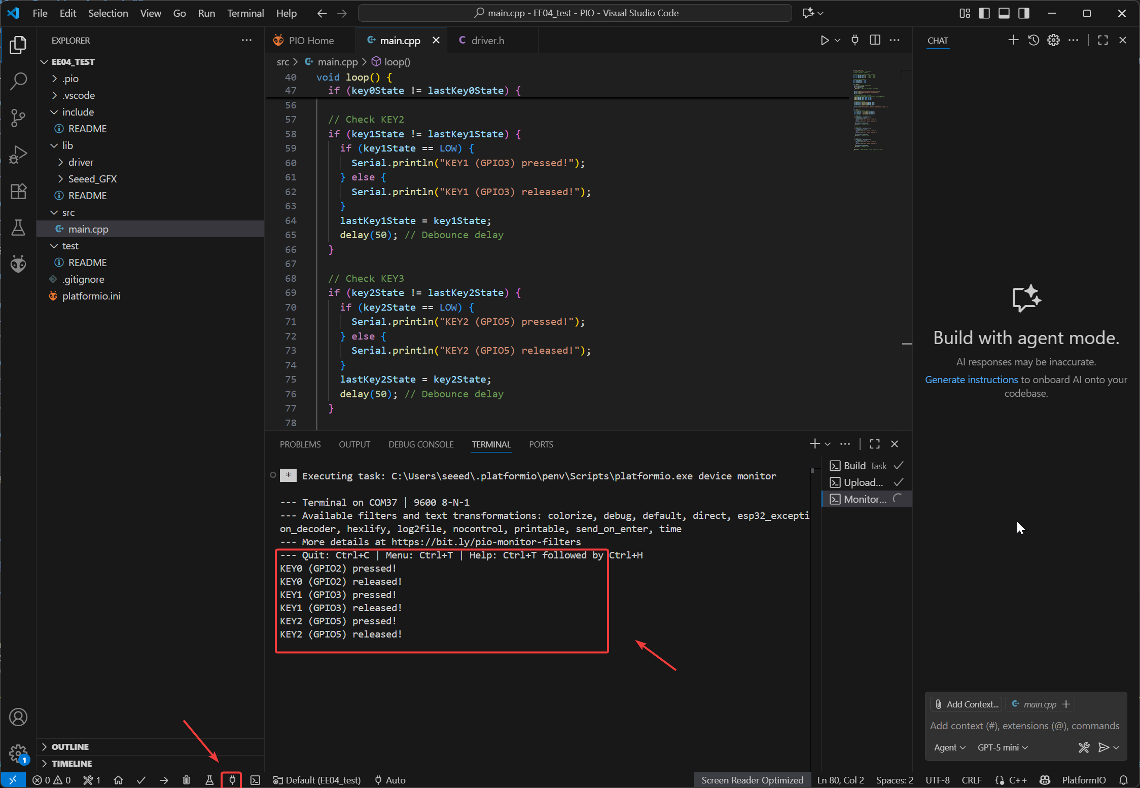
- Effect Demonstration:
The Serial Monitor can display the status of the serial port.
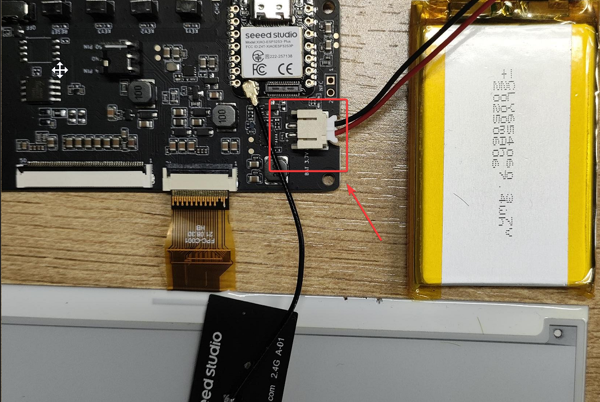
Battery Voltage
- The XIAO ePaper Display Board EE04 is powered by a 3.7V - 4.2V lithium battery. Additionally, there is an ADC interface for you to measure the voltage and monitor the battery voltage in real time.
- The ADC measurement pin is
A0 (GPIO1), and the ADC enable pin isD5 (GPIO_6).
Connnect:
The program for monitoring the battery voltage. It is for reference only.
#include <Arduino.h>

#define BATTERY_ADC A0  // Battery voltage ADC pin
#define ADC_EN 6        // ADC enable pin
#define VOLTAGE_DIVIDER_RATIO 2.0  // Voltage divider ratio (adjust based on your resistor values) ((R1+R2)/R2)

// Function to read battery voltage
static float readBatteryVoltage() {
  int sum = 0;
  // Read multiple samples for better accuracy
  for (int i = 0; i < 10; i++) {
    sum += analogRead(BATTERY_ADC);
    delay(2);
  }
  int adcValue = sum / 10;

  // Calculate actual battery voltage
  // Formula: voltage = (ADC_value / 4095) * 3.3V * divider_ratio
  float voltage = (adcValue / 4095.0) * 3.3 * VOLTAGE_DIVIDER_RATIO;

  return voltage;
}

void setup() {
  Serial.begin(115200);
  delay(1000);

  analogReadResolution(12);  // Set ADC resolution to 12 bits
  pinMode(BATTERY_ADC, INPUT);

  pinMode(ADC_EN, OUTPUT);
  digitalWrite(ADC_EN, HIGH);  // Enable ADC
}

void loop() {
  float batteryVoltage = readBatteryVoltage();

  Serial.print("Battery Voltage: ");
  Serial.print(batteryVoltage, 2);
  Serial.println(" V");

  delay(500);  // Read every 0.5 seconds
}
Code Explanation:
-
Main Functions:
- Battery Voltage Acquisition: Read the resistor-divided battery voltage via the ADC pin (battery voltage may exceed Arduino’s ADC reference voltage, requiring division first).
- Accuracy Optimization: Reduce circuit noise interference by averaging multiple samples.
- Voltage Conversion: Convert ADC’s digital signal to actual battery voltage (accounting for voltage division ratio and reference voltage).
- Serial Output: Periodically print measured voltage via serial port for external devices (e.g., computer) to view.
-
Core Functions & Roles
-
setup()(Initialization Function)- Role: Runs once on program start to configure hardware and parameters.
- Key Operations:
Serial.begin(115200): Initialize serial communication (baud rate 115200) for voltage data output.analogReadResolution(12): Set ADC resolution to 12-bit (reading range: 0~4095) for higher accuracy.pinMode(BATTERY_ADC, INPUT): Set battery detection pin (A0) to input mode for analog signals.pinMode(ADC_EN, OUTPUT)&digitalWrite(ADC_EN, HIGH): Enable ADC module (for low-power use: turn on only when measuring).
-
loop()(Main Loop Function)- Role: Runs repeatedly post-initialization for periodic voltage detection and output.
- Key Operations:
- Call
readBatteryVoltage()to get current battery voltage. - Use
Serial.print()/Serial.println()to print formatted voltage (2 decimal places, e.g., "Battery Voltage: 3.82 V"). delay(500): Set 0.5-second interval between measurements.
- Call
-
readBatteryVoltage()(Core Measurement Function)- Role: Read ADC signals, optimize results, and convert to actual voltage.
- Key Operations:
- Average Sampling: Read ADC 10 times, sum, then average (reduce noise).
analogRead(BATTERY_ADC): Read analog voltage from pin A0 (returns 0~4095).delay(2): 2ms interval between samples for stability.- Voltage Calculation: Use formula
(adcValue / 4095.0) * 3.3 * VOLTAGE_DIVIDER_RATIOto get real battery voltage. - Return the calculated voltage (float type) for
loop()to use.
-
-
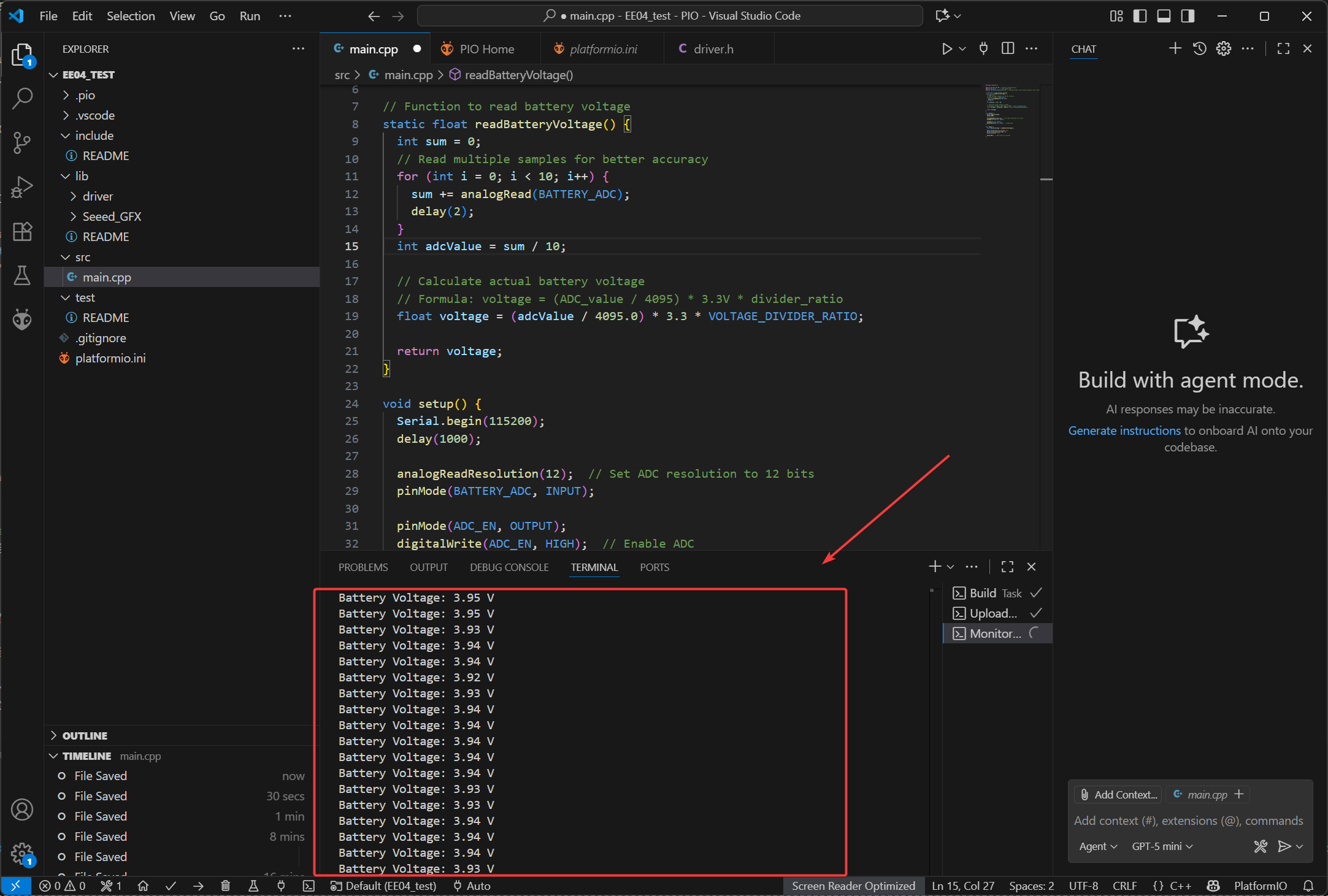
Effect Demonstration:
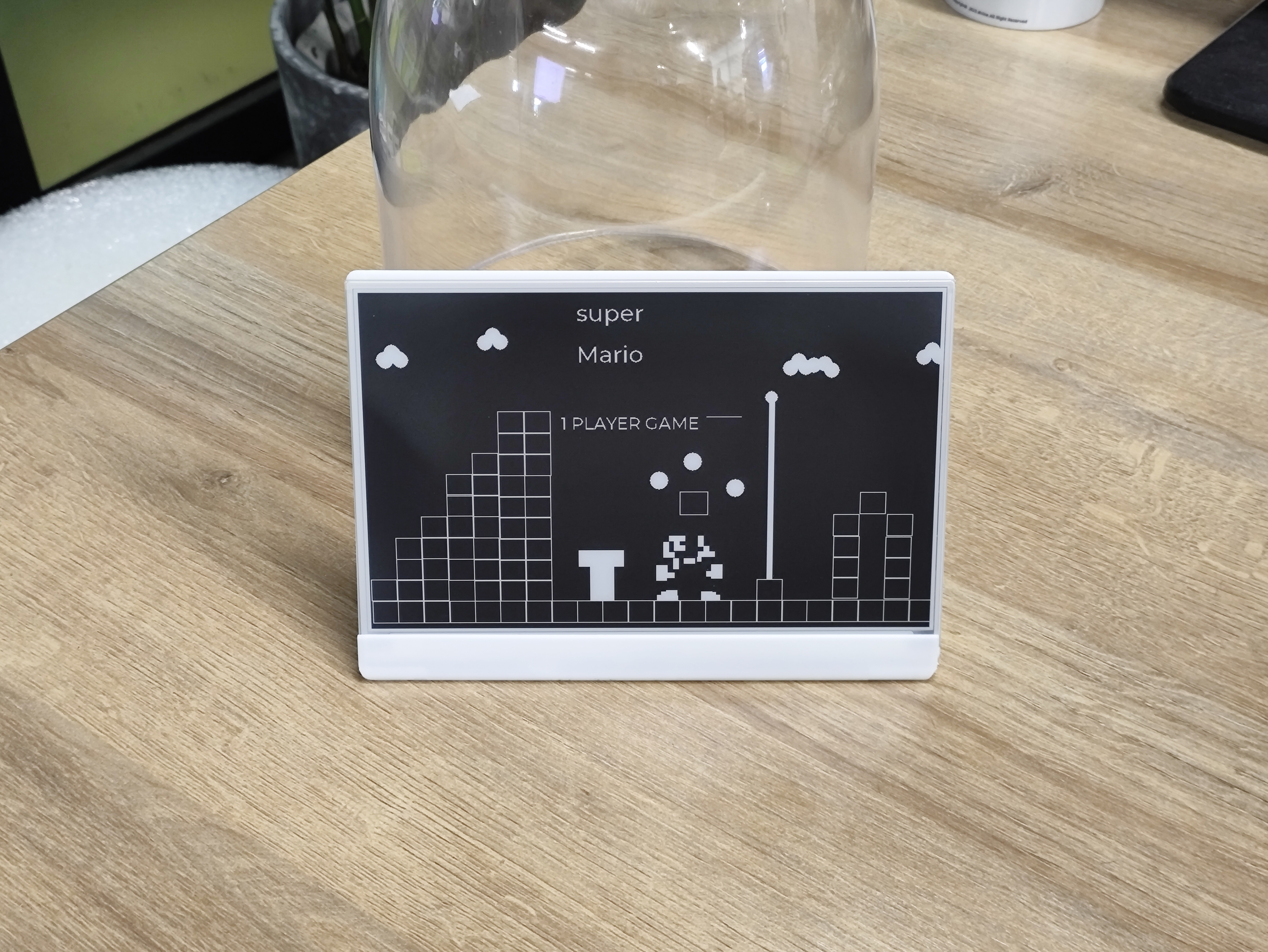
UI Design
EE04 enables you to carry out various creative designs, such as dashboards and image displays. By combining with buttons, it allows for the switching between multiple pages. Here is an example of a dashboard.
In this routine, the operation of drawing the dashboard is carried out based on the LVGL library.
LVGL Official Documentation: LVGL docs
Software
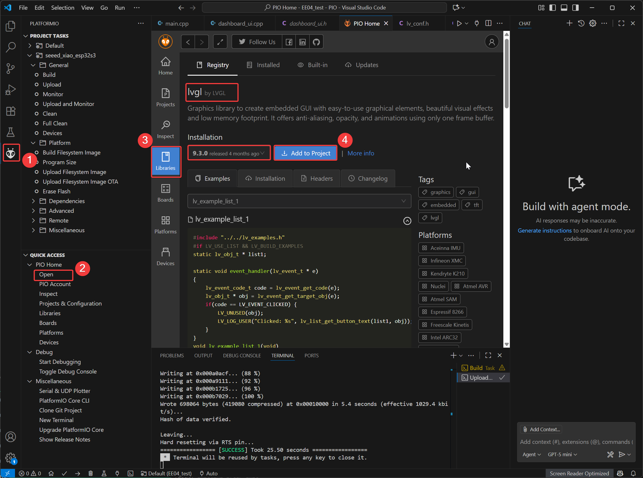
- Add the LVGL library. In the Library tool of the PIO Home interface, search for LVGL, and then select to add the library to the current project. It is recommended that you choose a version of LVGL 9.0 or above.
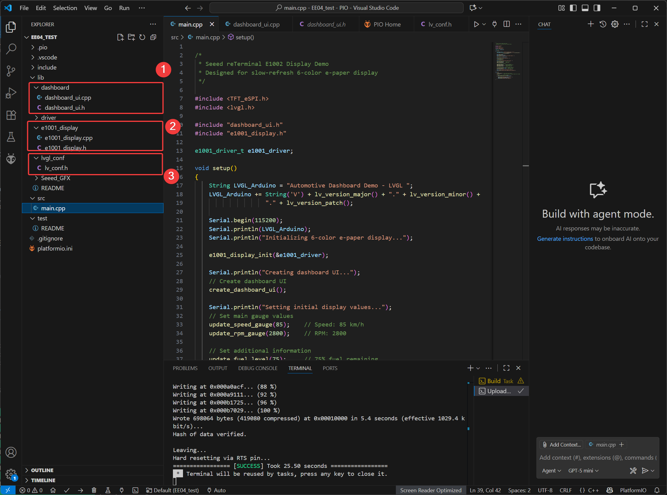
- In the lib directory
- Create a dashboard folder then create the
dashboard_ui.cppanddashboard_ui.hfiles. These files are mainly used to store the drawing code for LGVL. - Create the e1001_display folder, and add the screen driver files
e1001_display.cande1001_display.h - Create the lvgl_conf folder and add the configuration file
lv_conf.hof LVGL.
- Create a dashboard folder then create the
Complete reference code: EE04_Dashboard_ui.zip
main.cpp Code
/*
 * Seeed reTerminal E1001 Multi-UI Demo
 * - All hardware I/O and e-paper driver work happens here.
 * - All runtime parameters and debug logs live here.
 * - dashboard_ui.cpp is a pure LVGL UI layer (no driver calls, no runtime params).
 *
 * UI switching:
 *   KEY0 (GPIO2) → Vehicle Dashboard
 *   KEY1 (GPIO3) → Smart Home
 *   KEY2 (GPIO5) → Super Mario (default)
 */

#include <TFT_eSPI.h>
#include <lvgl.h>

#include "dashboard_ui.h"  // Pure UI layer
#include "e1001_display.h" // E1001 e-paper driver (init/refresh in this file only)

/* ============ Global driver object ============ */
static e1001_driver_t e1001_driver;

/* ============ Current UI ============ */
static UIType current_ui = UI_SUPER_MARIO;

/* ============ Smart Home runtime parameters (tuned here) ============ */
static String smh_location = "New York";
static String smh_weather = "Sunny";
static float smh_temperature = 22.5f;
static int smh_humidity = 45;
static float smh_batt_voltage = 12.4f;
static int smh_batt_capacity = 85;
static int smh_wifi_signal = 4; // 0..4

/* ============ Vehicle runtime parameters (tuned here) ============ */
static int veh_speed = 85;        // km/h
static int veh_rpm = 2800;        // RPM
static int veh_fuel = 75;         // %
static int veh_engine_temp = 82;  // °C
static char veh_gear = 'D';       // gear char
static long veh_odometer = 86531; // km
static bool veh_seatbelt = true;  // indicator example

/* ---------------------------------------------------------------
 * LVGL periodic tick (moved here from dashboard_ui.cpp)
 * --------------------------------------------------------------- */
void ui_update_loop()
{
    lv_timer_handler();
    delay(50);
}

/* ---------------------------------------------------------------
 * Rebuild the active screen for a given UI type (moved here)
 * --------------------------------------------------------------- */
void load_ui(UIType type)
{
    lv_obj_clean(lv_scr_act());
    current_ui = type;

    switch (type)
    {
    case UI_VEHICLE_DASHBOARD:
        create_vehicle_dashboard_ui();
        break;
    case UI_SMART_HOME:
        create_smarthome_ui();
        break;
    case UI_SUPER_MARIO:
    default:
        create_supermario_ui();
        break;
    }
}

/* ---------------------------------------------------------------
 * Helper to apply Smart Home params to the active UI (if loaded)
 * --------------------------------------------------------------- */
static void apply_smarthome_params()
{
    update_temperature(smh_temperature);
    update_humidity(smh_humidity);
    update_battery_voltage(smh_batt_voltage);
    update_battery_capacity(smh_batt_capacity);
    update_wifi_signal(smh_wifi_signal);
    update_weather_status(smh_weather.c_str());
    update_location(smh_location.c_str());

    // Example to-do placeholders (UI has checkboxes already)
    add_todo_item("Water plants");
    add_todo_item("Check security");
    add_todo_item("Update firmware");
    add_todo_item("Check smart plugs");
}

/* -------------------------------------------------------------
 * Helper to apply Vehicle params to the active UI (if loaded)
 * ------------------------------------------------------------- */
static void apply_vehicle_params()
{
    update_speed_gauge(veh_speed);
    update_rpm_gauge(veh_rpm);
    update_fuel_level(veh_fuel);
    update_engine_temp(veh_engine_temp);
    update_gear_position(veh_gear);
    update_odometer(veh_odometer);
    set_warning_indicator(0, veh_seatbelt);
}

/* -------------------------------------------------------------
 * Switch UI (rebuilds the UI and applies current parameters)
 * ------------------------------------------------------------- */
static void switch_ui(UIType next_ui)
{
    if (next_ui == current_ui)
        return;

    current_ui = next_ui;
    load_ui(current_ui);

    if (current_ui == UI_VEHICLE_DASHBOARD)
    {
        Serial.println("[UI] Loaded Vehicle Dashboard");
        apply_vehicle_params();
    }
    else if (current_ui == UI_SMART_HOME)
    {
        Serial.println("[UI] Loaded Smart Home");
        apply_smarthome_params();
    }
    else
    {
        Serial.println("[UI] Loaded Super Mario");
    }

    // Trigger an e-paper refresh immediately after rebuilding UI
    e1001_display_refresh(&e1001_driver);
}

/* -------------------------------------------------------------
 * Setup
 * ------------------------------------------------------------- */
void setup()
{
    Serial.begin(115200);
    Serial.println("LVGL Multi-UI + E1001 e-paper demo starting...");

    // Configure keys (active LOW due to INPUT_PULLUP)
    pinMode(BUTTON_KEY0, INPUT_PULLUP);
    pinMode(BUTTON_KEY1, INPUT_PULLUP);
    pinMode(BUTTON_KEY2, INPUT_PULLUP);

    // Initialize e-paper (includes LVGL/timer/display config handled by your driver)
    Serial.println("Initializing E1001 e-paper driver...");
    e1001_display_init(&e1001_driver);
    Serial.println("E1001 init done.");

    // Default UI: Super Mario
    current_ui = UI_SUPER_MARIO;
    load_ui(current_ui);
    Serial.println("Default UI created: Super Mario");

    e1001_display_refresh(&e1001_driver);
}

/* -------------------------------------------------------------
 * Loop: button-based UI switching + LVGL ticks + e-paper refresh
 * ------------------------------------------------------------- */
void loop()
{
    // Handle UI switching (debounced)
    if (digitalRead(BUTTON_KEY0) == LOW)
    { // Vehicle
        switch_ui(UI_VEHICLE_DASHBOARD);
        delay(300);
    }
    else if (digitalRead(BUTTON_KEY1) == LOW)
    { // Smart Home
        switch_ui(UI_SMART_HOME);
        delay(300);
    }
    else if (digitalRead(BUTTON_KEY2) == LOW)
    { // Super Mario
        switch_ui(UI_SUPER_MARIO);
        delay(300);
    }

    // Drive LVGL internal timers only (no driver I/O in UI layer)
    ui_update_loop();

    // Check if e-paper refresh is needed (driver logic stays here)
    if (e1001_display_should_refresh(&e1001_driver))
    {
        Serial.println("Refreshing e-paper display...");
        e1001_display_refresh(&e1001_driver);
        Serial.println("Display refresh complete.");
    }
}
Effect Demonstration
Pressing the buttons on the EE04 board can switch to the corresponding UI interface:
- KEY1: Vehicle Dashboard
- KEY2: SmartHome Dashboard
- KEY3: Super Mario
- Default: Super Mario
| Super Mario | Vehicle | SmartHome |
|---|---|---|
| 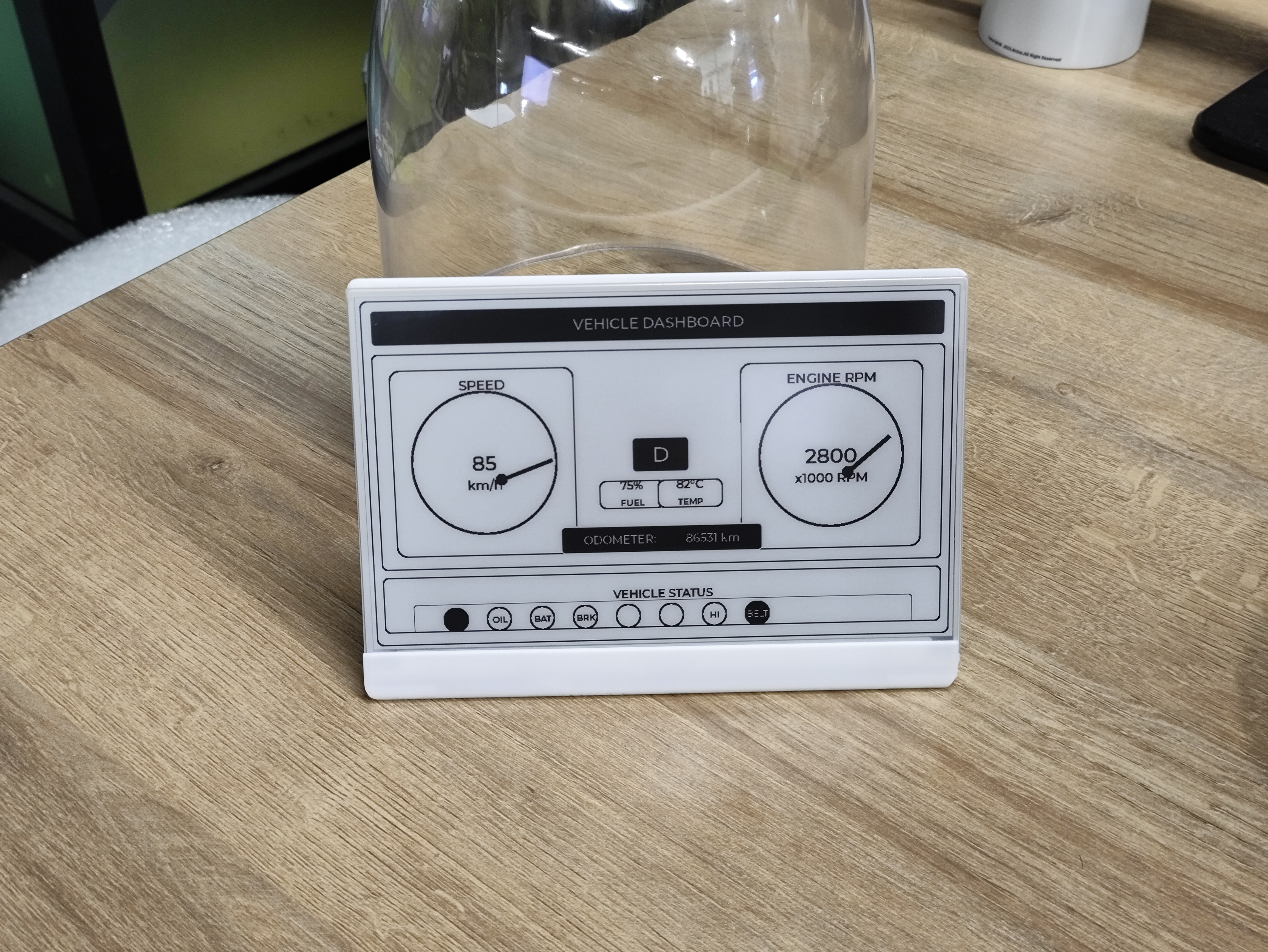 | 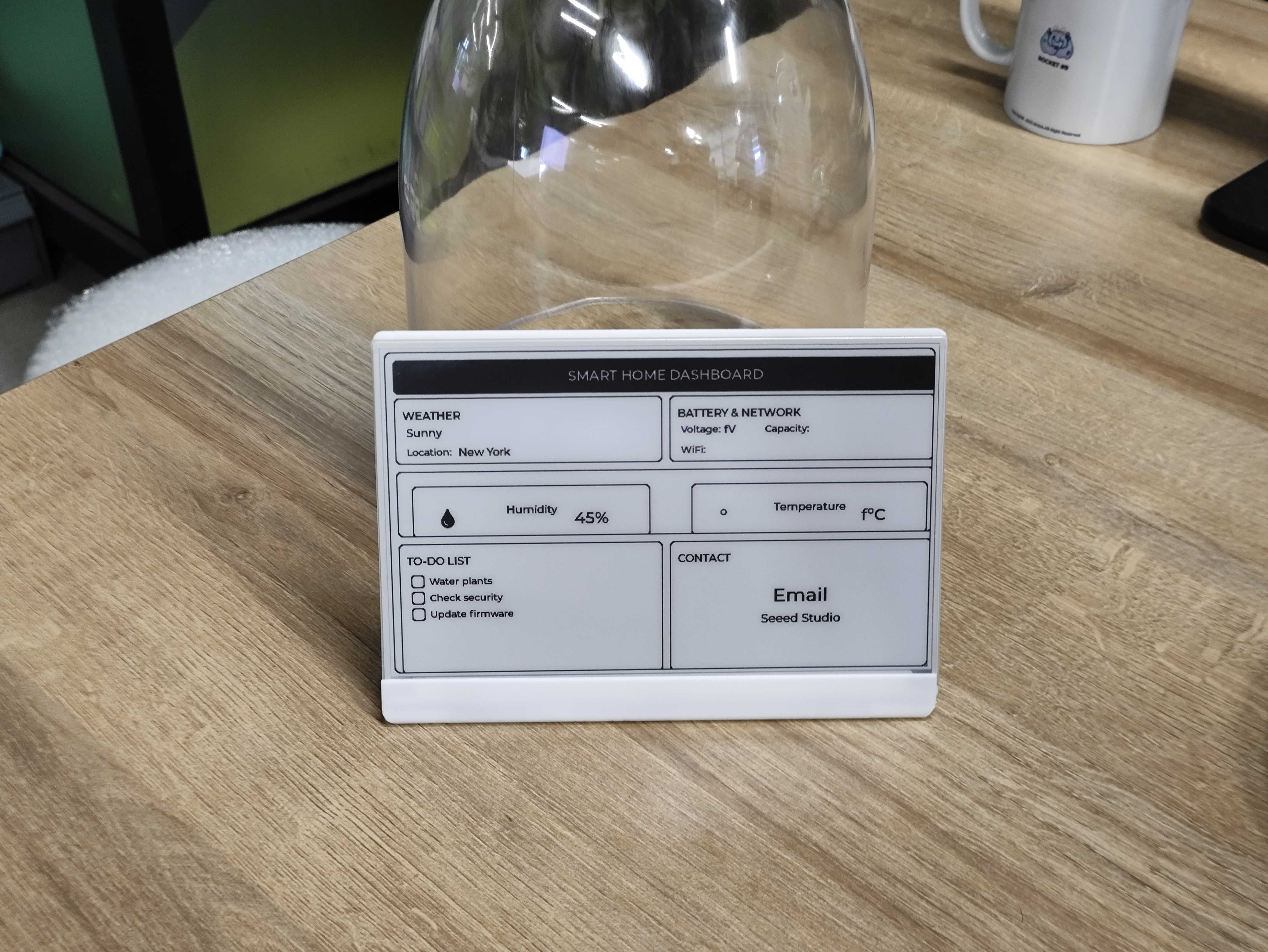 |
Resource
- 7.5" Monochrome eInk Enclosure (3D Model): Download from Printables
Tech Support & Product Discussion
Thank you for choosing our products! We are here to provide you with different support to ensure that your experience with our products is as smooth as possible. We offer several communication channels to cater to different preferences and needs.