Getting Started with XIAO ePaper Display Board - EE04
| XIAO ePaper Display Board EE04 |
|---|
 |
Introduction
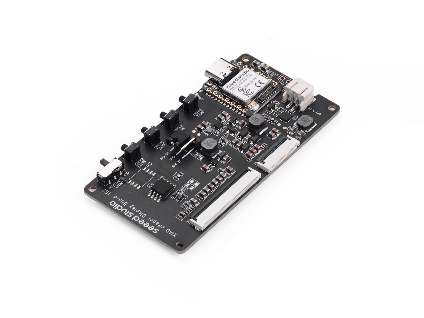
Powered by XIAO ESP32-S3 Plus, the display board EE04 supports both 24-pin and 50-pin ePaper displays. It features a JST 2.0 mm battery connector with power switch, built-in charging IC, and comes with one reset and three user buttons. Well-suited for low-power ePaper projects such as digital signage, electronic labels, and portable information boards.
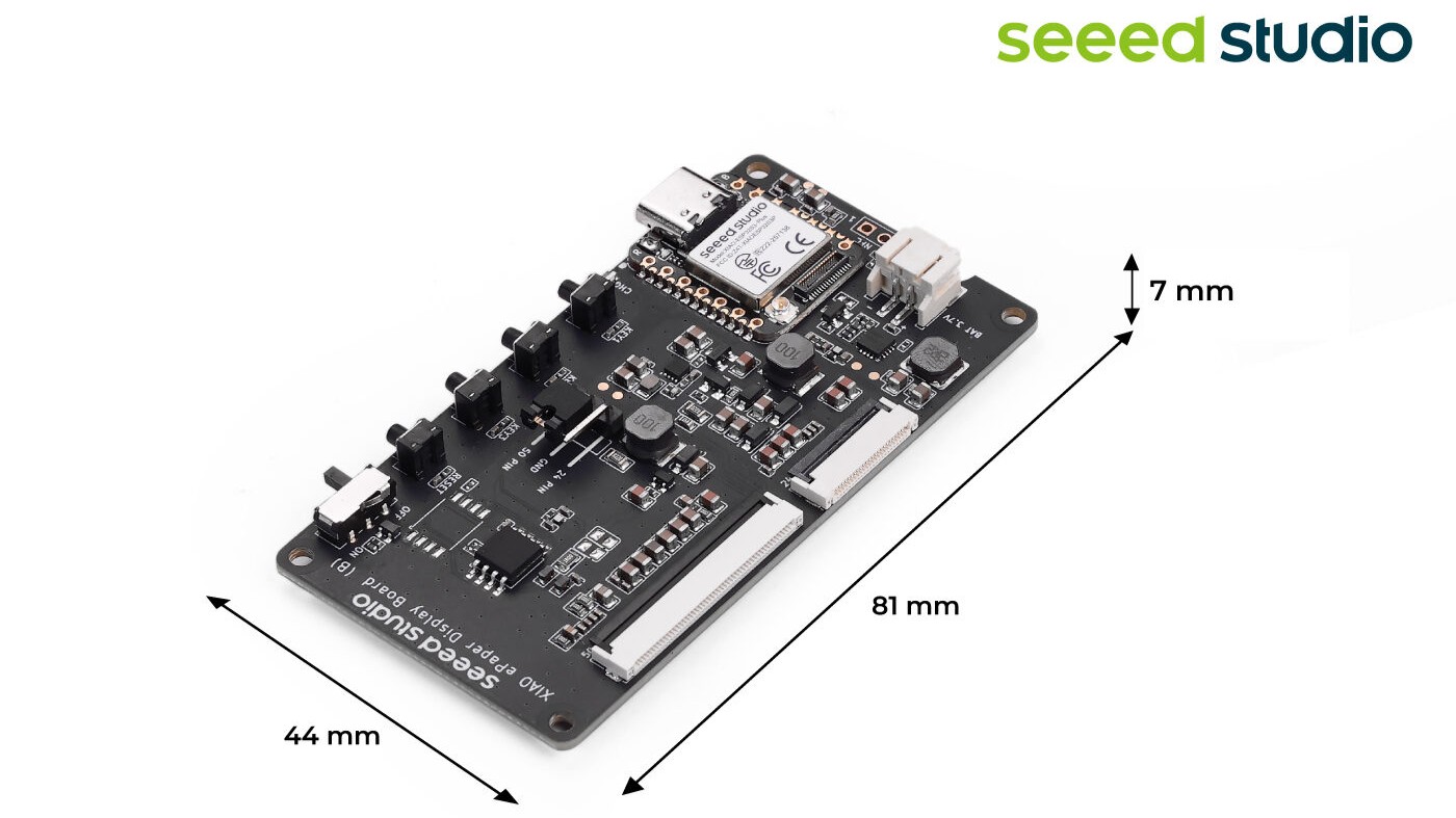
Featrue
- Powered by XIAO ESP32-S3 Plus: Works immediately when connected to a compatible ePaper display.
- Versatile Display Support: Compatible with a wide range of ePaper screens, supporting both 24-Pin and 50-Pin interfaces with easy switching via jumper caps.
- BAT Connector with Switch: Provides simple battery connection and integrates a switch, enabling efficient power management and energy savings.
- User-Friendly Buttons: Includes 1 reset button and 3 user-programmable buttons, offering flexibility for project acceleration and customizable functions.
- Low Power Design: Suitable for battery-powered ePaper applications with typically 3-month on a full charge under default settings.
Specification
| Parameter | Description |
|---|---|
| Processor | XIAO ESP32-S3 Plus |
| ePaper Connector | FPC 24 Pin 0.5mm FPC 50 Pin 0.5mm |
| Battery Connector | JST 2.0mm |
| Switch | Battery Power ON/OFF |
| Power Supply | - 3.7V Li-Battery - USB Type-C |
| Button | - 1x Reset button - 3x User button |
ePaper Board Selection Guide
| Product | ePaper Display Board EE04 | ePaper Breakout | ePaper Driver Board |
|---|---|---|---|
| Processor | XIAO ESP32-S3 Plus | XIAO Series | XIAO Series |
| Compatible ePaper Displays | 24 Pin ePaper 50 Pin ePaper | 24 Pin ePaper | 24 Pin ePaper |
| ePaper Connector | FPC 24 Pin, 0.5mm FPC 50 Pin, 0.5mm | FPC 24 Pin 0.5mm | FPC 24 Pin 0.5mm |
| Battery Connector | JST 2.0mm | / | JST 2.0mm |
| Switch | Battery Power ON/OFF | / | Battery Power ON/OFF |
| Button | 1x Reset button 3x User button | / | / |
| Extension IO Port | / | connection of others controller | connection of additional sensors |
Application
- Smart Home Dashboard: Display real-time information such as weather updates, calendar events, and notifications from various smart home devices.
- Energy Monitoring: Show energy consumption data from smart meters, helping homeowners track and manage their energy usage more efficiently.
- Security Alerts: Display alerts and notifications about security events, such as motion detection or door/window sensor activation.
- Smart Thermostat Display: Show temperature and humidity levels, as well as control settings for your smart thermostat.
- Digital Photo Frame: Create a WiFi-enabled digital photo frame that can display images from your smart home network.
Hardware Overview
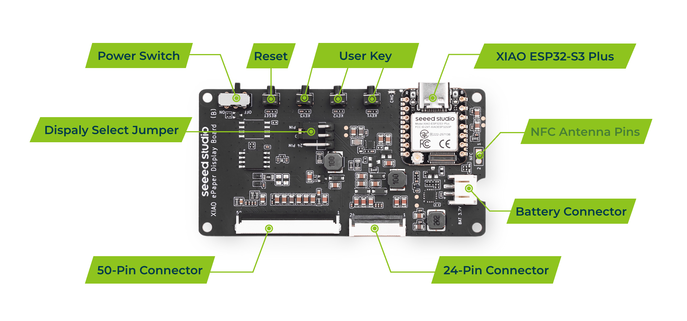
This version XIAO ePaper Display Board(ESP32-S3) - EE04 does not support NFC functionality.
Supported ePaper
24-Pin Connector
- 1.54-inch ePaper - Monochrome 200x200
- 2.13-inch ePaper - Monochrome 122x250
- 2.13-inch ePaper - Quadruple 122x250
- 2.9-inch ePaper - Monochrome 296x128
- 2.9-inch ePaper - Flexible Monochrome 296x128
- 2.9-inch ePaper - Quadruple color 128x296
- 4.2-inch ePaper - Monochrome 400x300
- 4.26-inch ePaper - Monochrome 800x480
- 5.83-inch ePaper - Monochrome 648x480
- 7.5-inch ePaper - Monochrome 800x480
- 7.5-inch ePaper - Tri-Color 800x480
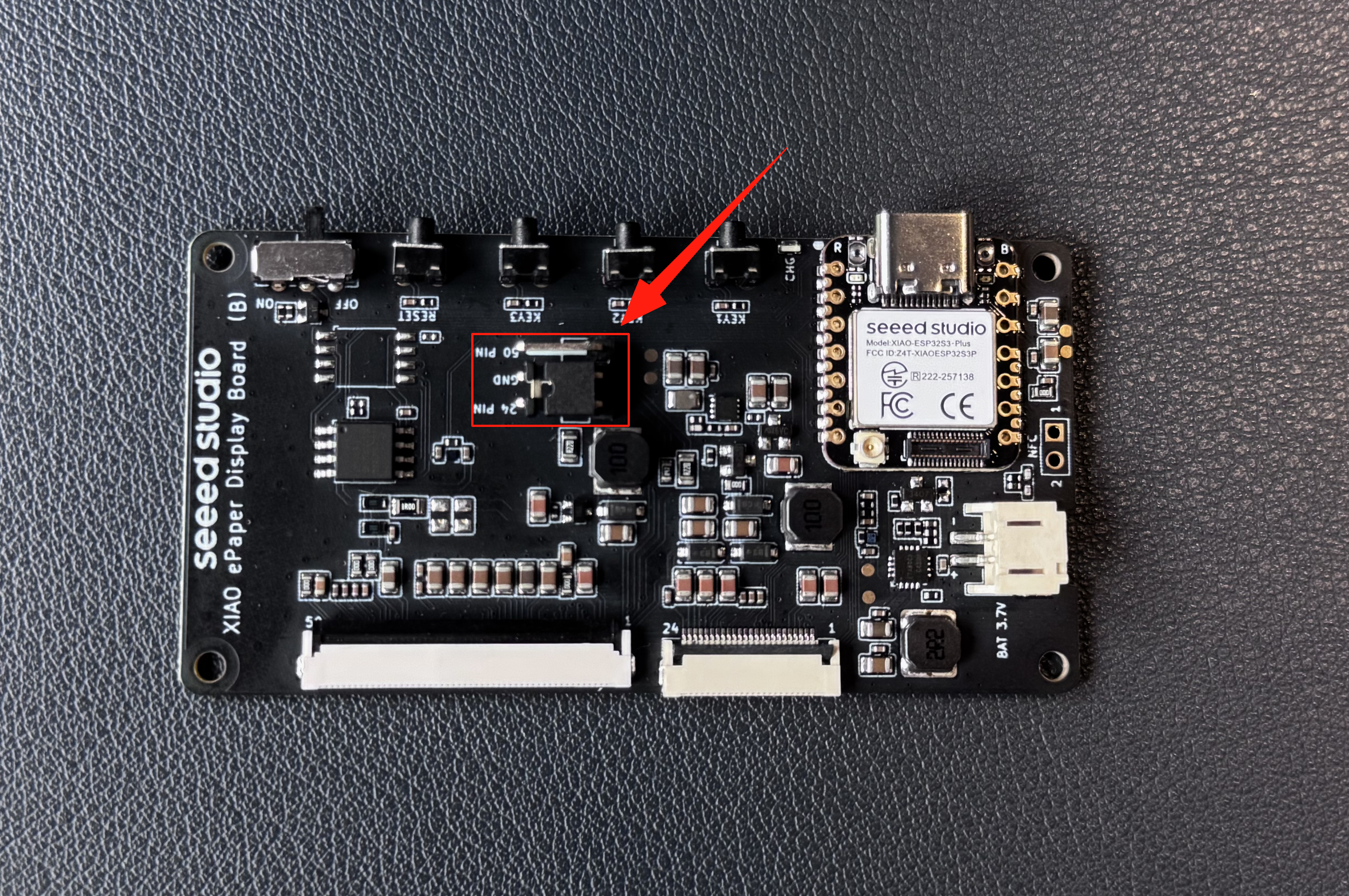
When using the XIAO ePaper Display Board, make sure to set the jumper according to the ePaper display type:
- For 24 Pin ePaper displays → set the jumper to 24 Pin
⚠️ Using the wrong jumper setting may cause the ePaper to fail to display or show abnormal content. Always double-check the jumper position before powering on.
50-Pin Connector
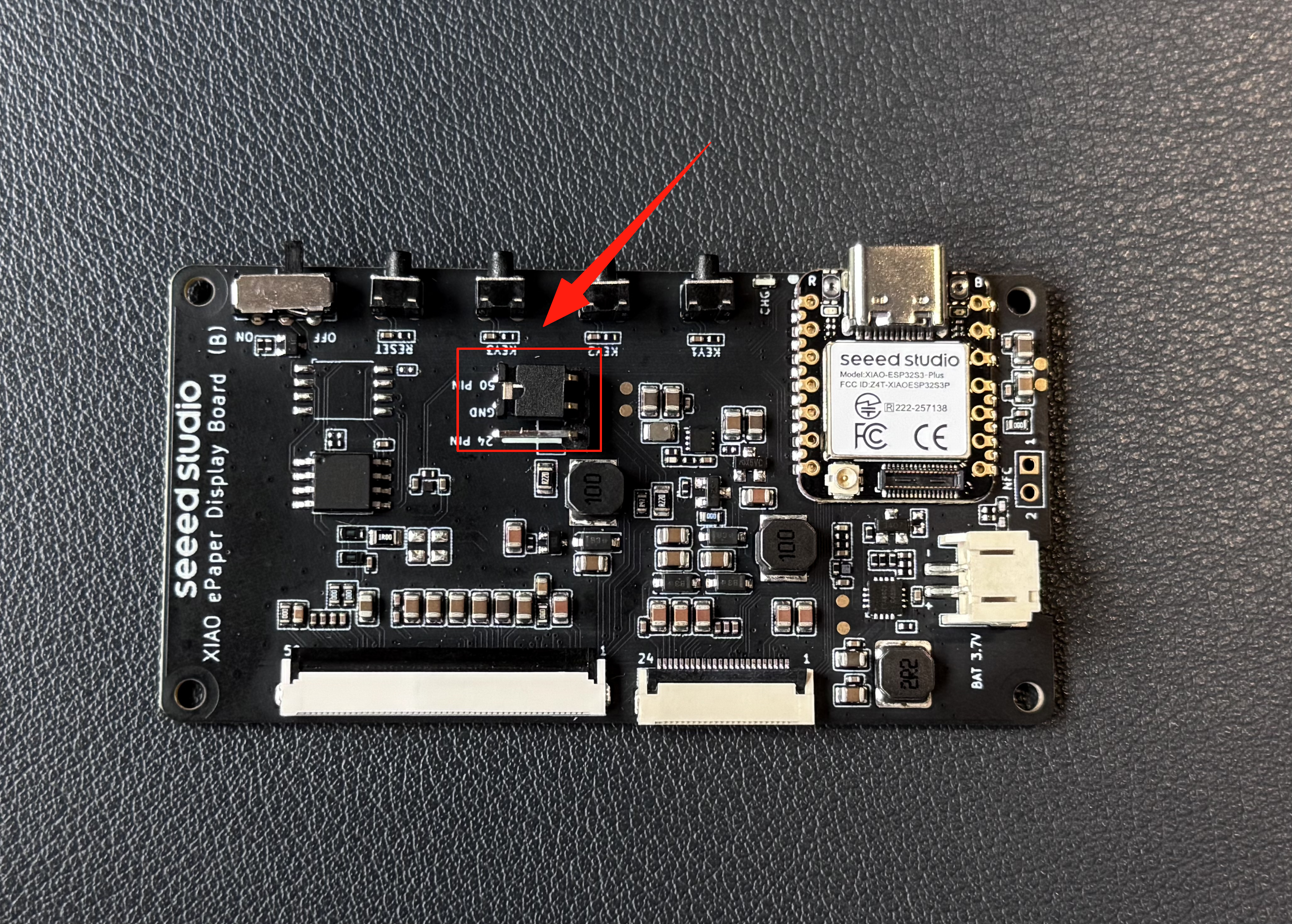
When using the XIAO ePaper Display Board, make sure to set the jumper according to the ePaper display type:
- For 50 Pin ePaper displays → set the jumper to 50 Pin
⚠️ Using the wrong jumper setting may cause the ePaper to fail to display or show abnormal content. Always double-check the jumper position before powering on.
Buttons
The EE04 is equipped with 1 reset button and 3 user-programmable buttons, providing flexibility for user interaction and project customization.
| Button | GPIO | Function |
|---|---|---|
| KEY0 | GPIO2_D1/A1 | User button (Programmable) |
| KEY1 | GPIO3_D2/A2 | User button (Programmable) |
| KEY2 | GPIO5_D4/A4 | User button (Programmable) |
| RESET | - | Reset button |
The user buttons are programmable and can be configured for various functions such as page switching, mode selection, or triggering specific actions in your ePaper project.
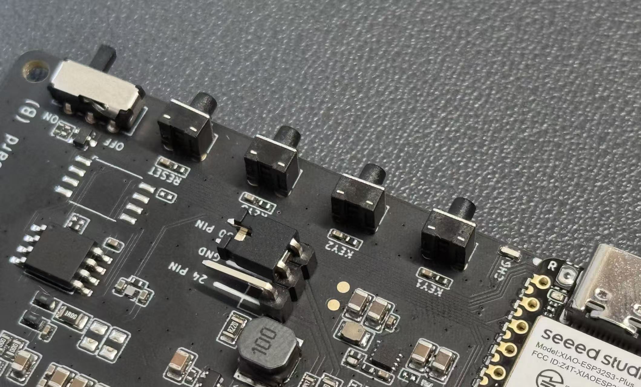
Jumper Cap Selection
The EE04 supports both 24-pin and 50-pin ePaper displays. Use the jumper cap to select the correct pin configuration for your display:
- 24-pin mode: Place the jumper cap on the 24-pin side
- 50-pin mode: Place the jumper cap on the 50-pin side
Make sure the jumper cap is correctly positioned according to your ePaper display pin count. Incorrect jumper cap placement may cause display issues or damage the screen.
Battery Connector
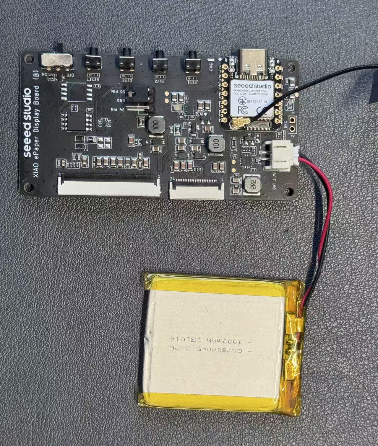
The board features a JST 2.0mm battery connector with a power switch, allowing you to power the device with a 3.7V lithium battery for portable applications. The built-in charging IC enables battery charging via USB Type-C.
When the device is powered by battery, the following phenomena are inherent normal behaviors of the SenseCraft Seeedash firmware itself.
- The device will automatically enter low-power mode between refreshes
- Battery life depends on refresh frequency (typically 3-month on a full charge with default settings)
- The device will display a low battery icon in the top-right corner when the battery level is below 20%
Getting Started with SenseCraft Seeedash
This section will guide you through connecting your EE04 to the SenseCraft Seeedash platform, allowing you to easily update the screen content wirelessly.
Which screen does this guide use? Unlike single-panel boards, the EE04 supports multiple ePaper panels (see the Supported ePaper section above). This guide uses the 7.5-inch Monochrome ePaper (800 x 480) as the example throughout — all screenshots below are taken with this panel. If you have a different screen, simply select your own panel model when flashing the firmware in Step 2; the remaining steps are exactly the same.
No welcome screen on first power-up? That is normal. Because the EE04 supports multiple ePaper panels, the factory firmware is not pre-flashed for any specific screen. When you connect a screen and power on a brand-new board, the display will most likely stay blank — this does not mean the board or screen is broken. You need to flash the SenseCraft Seeedash firmware matching your screen model first (Step 2 below); the welcome and Network Configuration interfaces will appear after flashing.
Equipment Installation
Step 1. Connect the Screen and Board Carefully connect the FPC cable of your ePaper screen to the connector on the EE04 driver board. Ensure the locking mechanism is secure.
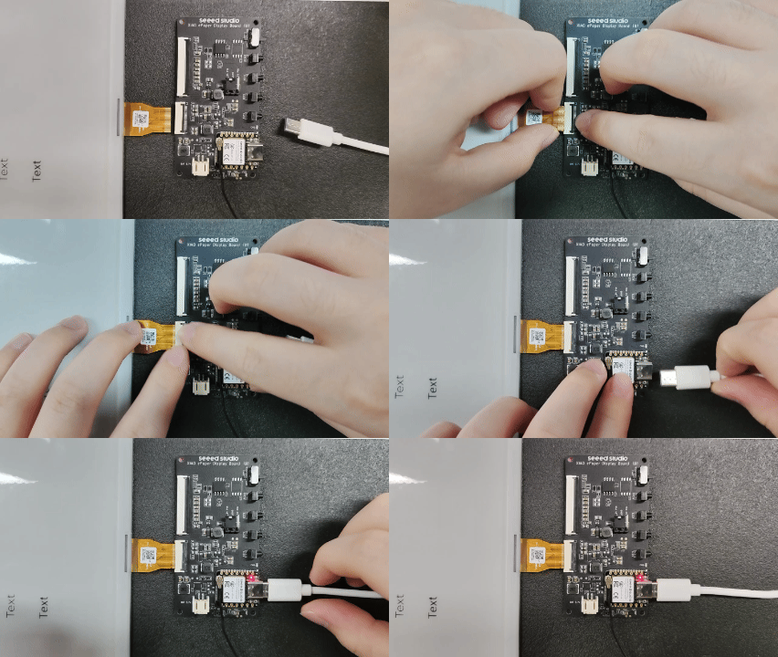
Step 2. Flash the HMI Firmware for Your Screen
Keep the EE04 board connected to your computer with a USB Type-C data cable (the same cable is used for power and flashing), then:
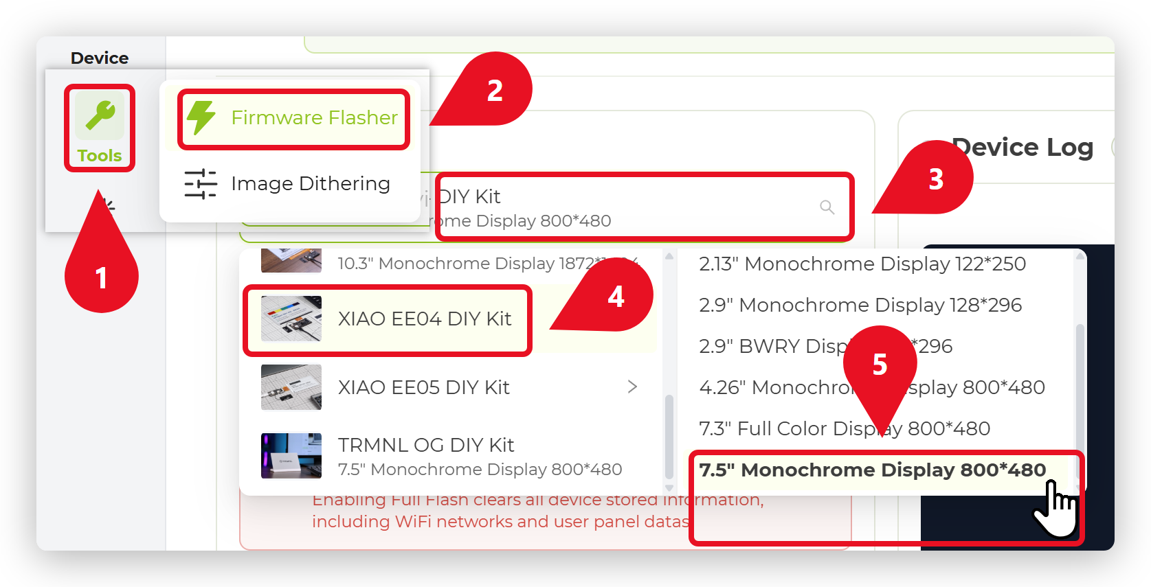
- Visit the SenseCraft Seeedash platform and sign in to your account.
- Open Tools → Firmware Flasher from the left menu.
- In the device list, select XIAO EE04 DIY Kit.
- Select the firmware entry that matches the screen model connected to your board. In this guide we use the 7.5" Monochrome Display 800 x 480 — pick your own panel here if it is different.
- Click Flash, choose the serial port of your board in the pop-up window, and wait for the flashing to complete.
If no serial port appears, press the RESET button on the board and try again. Also make sure your USB-C cable supports data transfer, not charging only.
Step 3. Enter Network Configuration Mode Once the firmware flashing is complete, the board reboots automatically. The screen first shows the welcome image, then refreshes to the Network Configuration interface. This indicates the device is ready to connect to Wi-Fi.
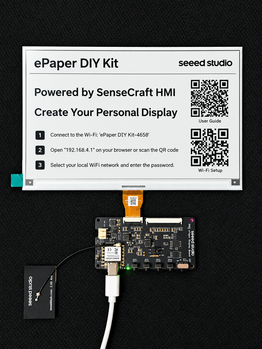
Network Configuration
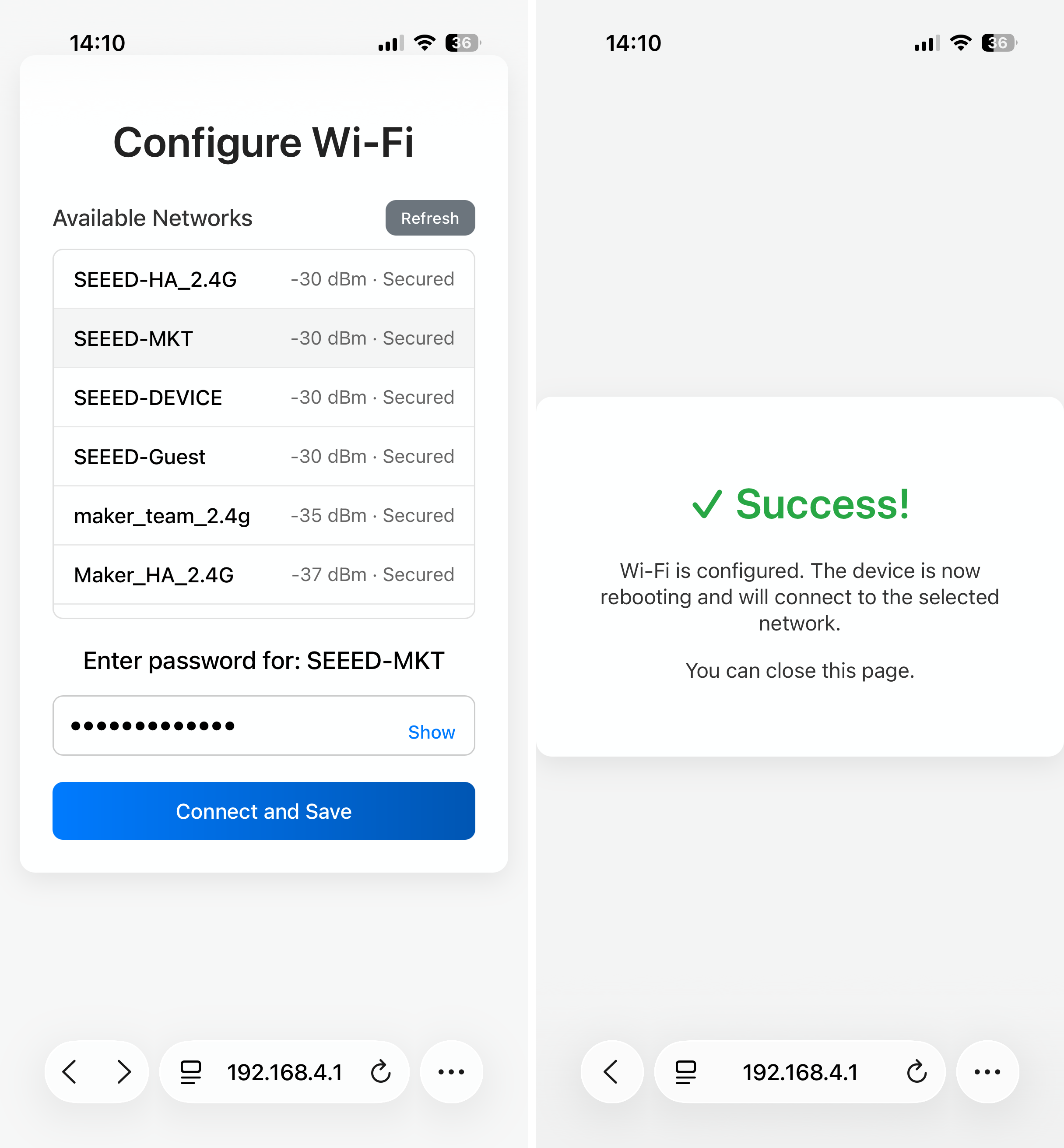
Step 4. Configure Wi-Fi via Mobile Phone Use your mobile phone to scan the QR code displayed on the screen. Follow the prompts on your phone to enter your local Wi-Fi SSID and password to connect the EE04 to the internet.
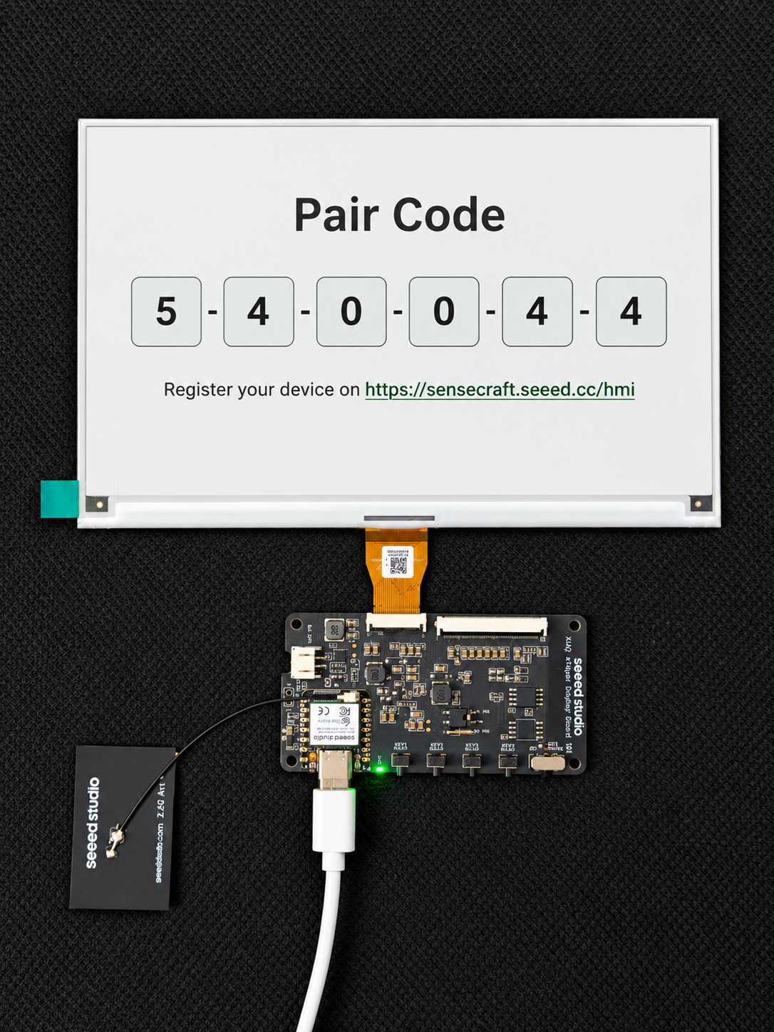
Step 5. Obtain Pair Code Once the network configuration is successful, the screen will refresh again and display a unique Pair Code. You will need this code for the next step.
Platform Binding & Update
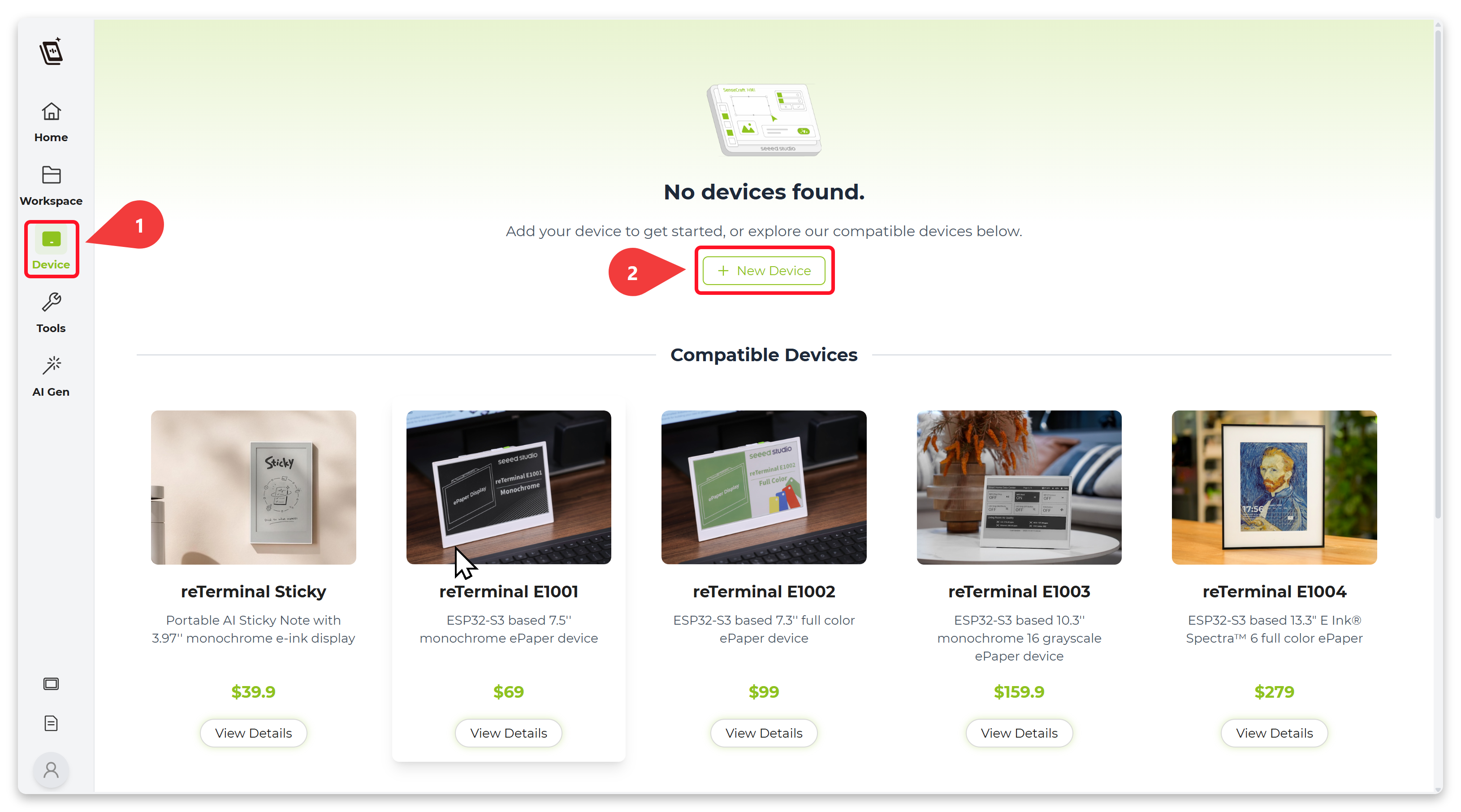
Step 6. Bind Device on SenseCraft Seeedash Go to the SenseCraft Seeedash Platform. Log in to your account. Navigate to the device management section and select "New Device". Enter the Pair Code displayed on your E-ink screen.
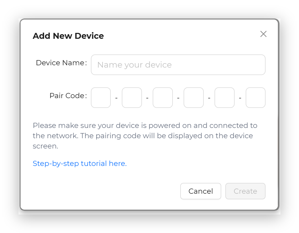
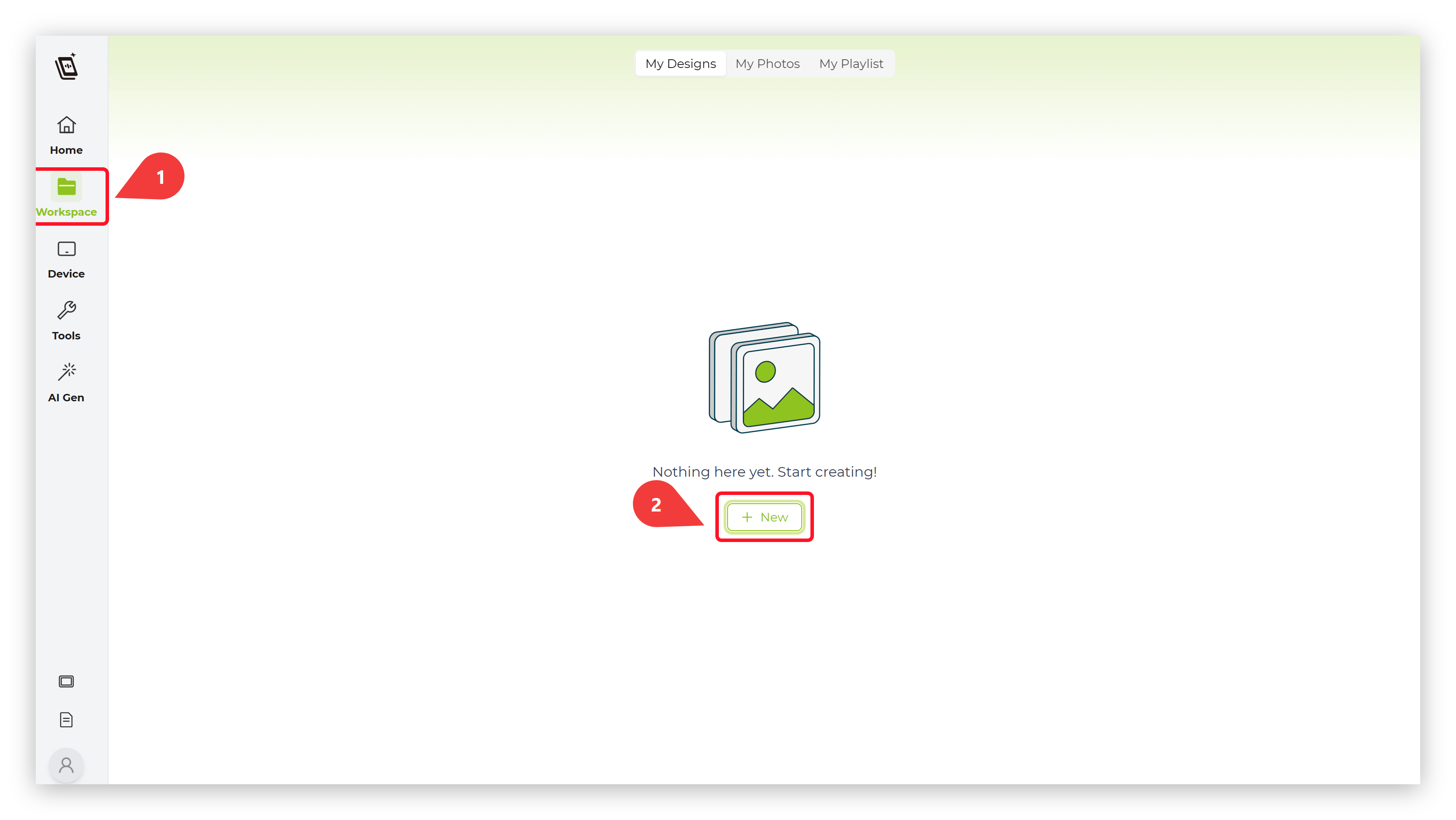
Step 7. Create and Push New Interface
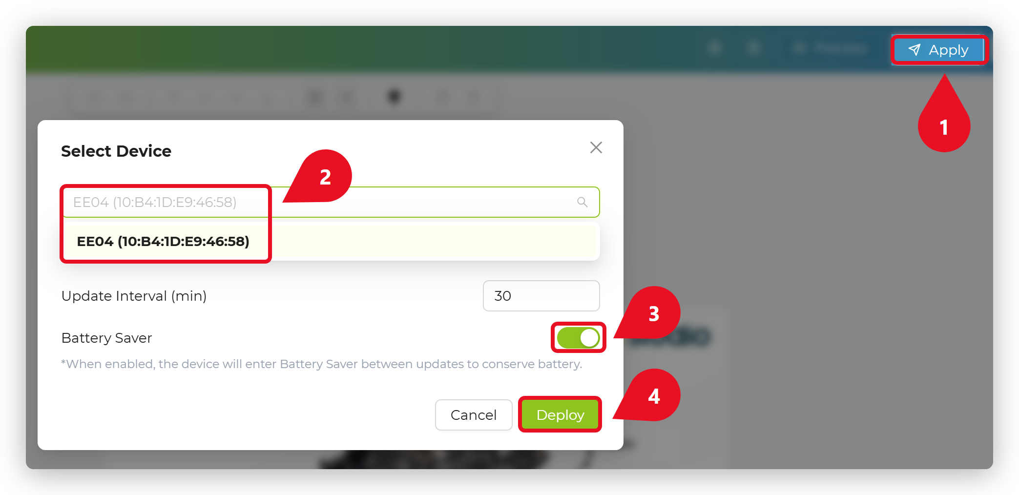
On the SenseCraft Seeedash platform, select the template suitable for the 7.5-inch screen to create a new interface or upload an image.
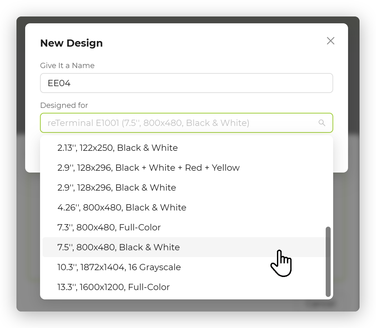
Step 8. Apply your images Once finished, click the "Apply" button and select your EE04 device.
Step 9. Display on the screen Finally the EE04 will receive the data and refresh the 7.5-inch screen with your new content.
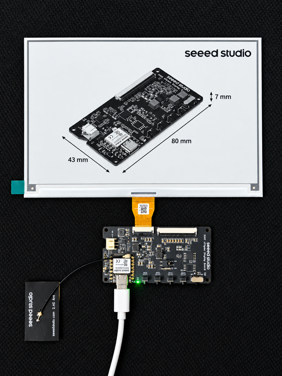
Getting Started with Arduino
Install Seeed GFX2 Library
This library has the same function as the TFT library and is not compatible with it. If you have installed the TFT library or other similar display libraries, please uninstall them first.
Download and install the Seeed GFX2 library from GitHub.
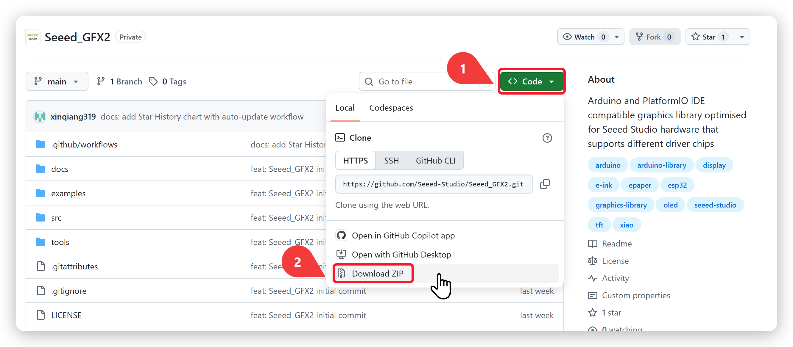
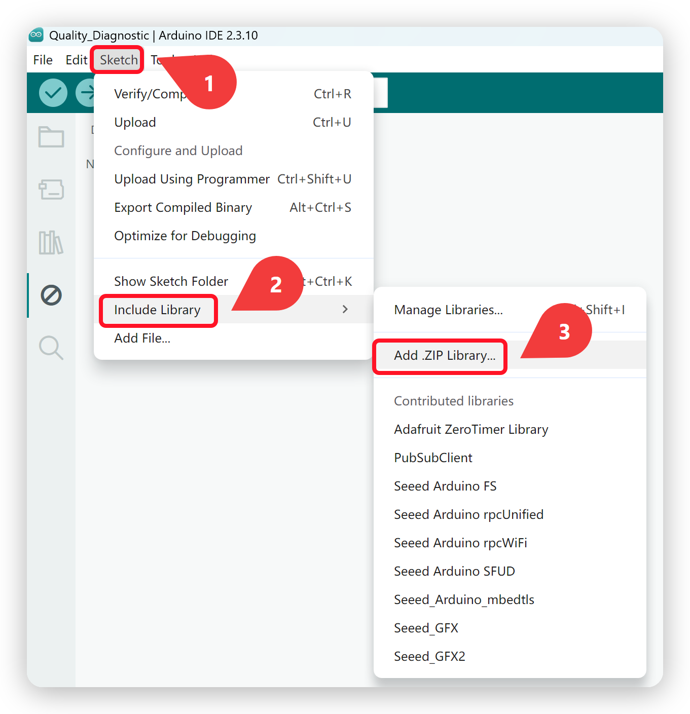
After downloading the library, go to Sketch -> Include Library -> Add .ZIP Library and select the downloaded library.
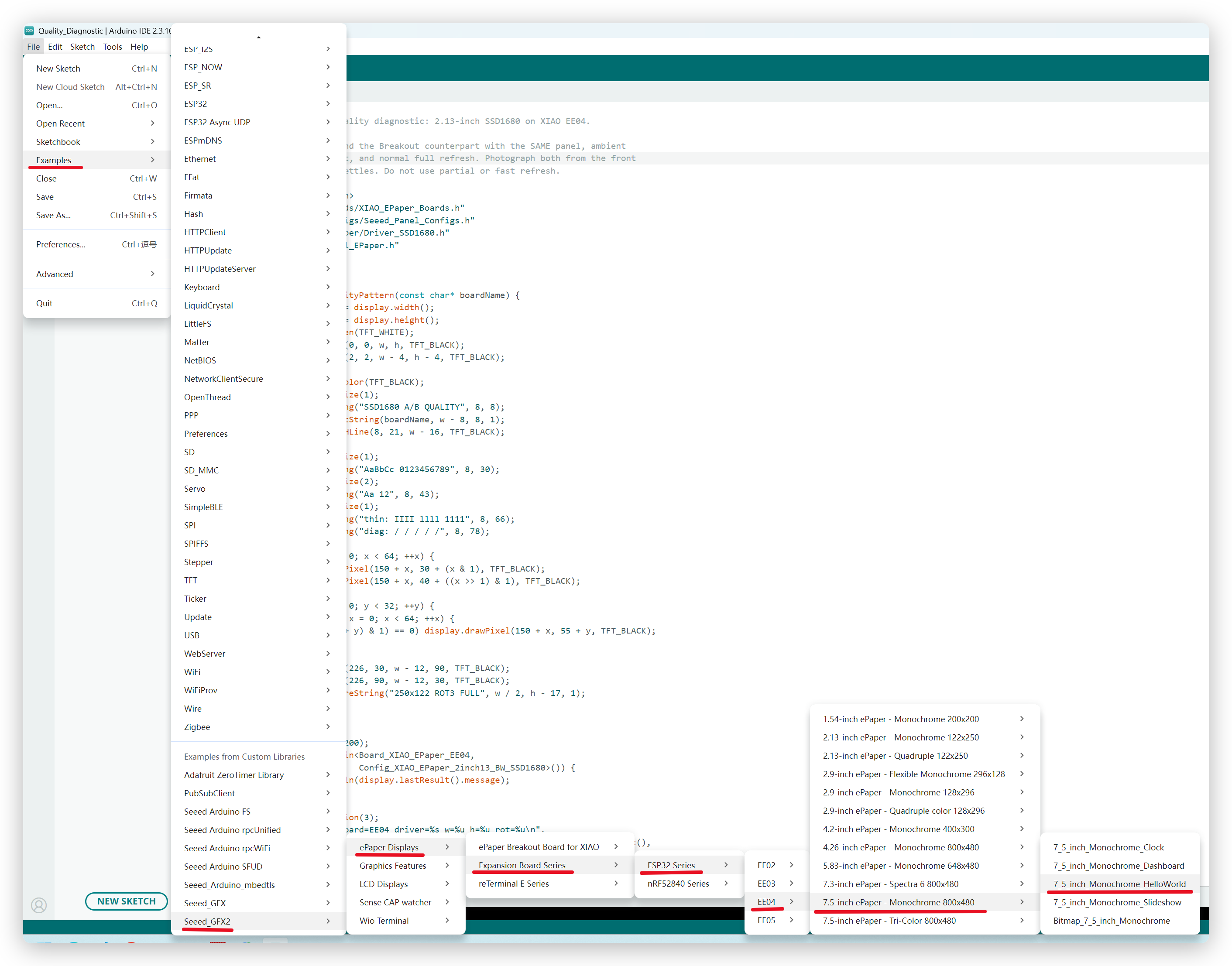
Configure and burn the program
As shown in the image, navigate to the example through this menu: File → Examples → Seeed_GFX2 → ePaper Displays → Expansion Board Series → ESP32 Series → XIAO ePaper Display Board - EE04 → 7.5-inch ePaper - Monochrome 800x480 → 7_5_inch_Monochrome_HelloWorld
This guide uses the 7.5-inch Monochrome ePaper (800 x 480) as the example. If you have a different screen, open the example folder that matches your own panel model under EE04 instead.
After that, go to Tools -> Board -> XIAO ESP32S3 Plus and Tools -> Port -> Select the port your board is connected to.
Note that PSRAM must be enabled.
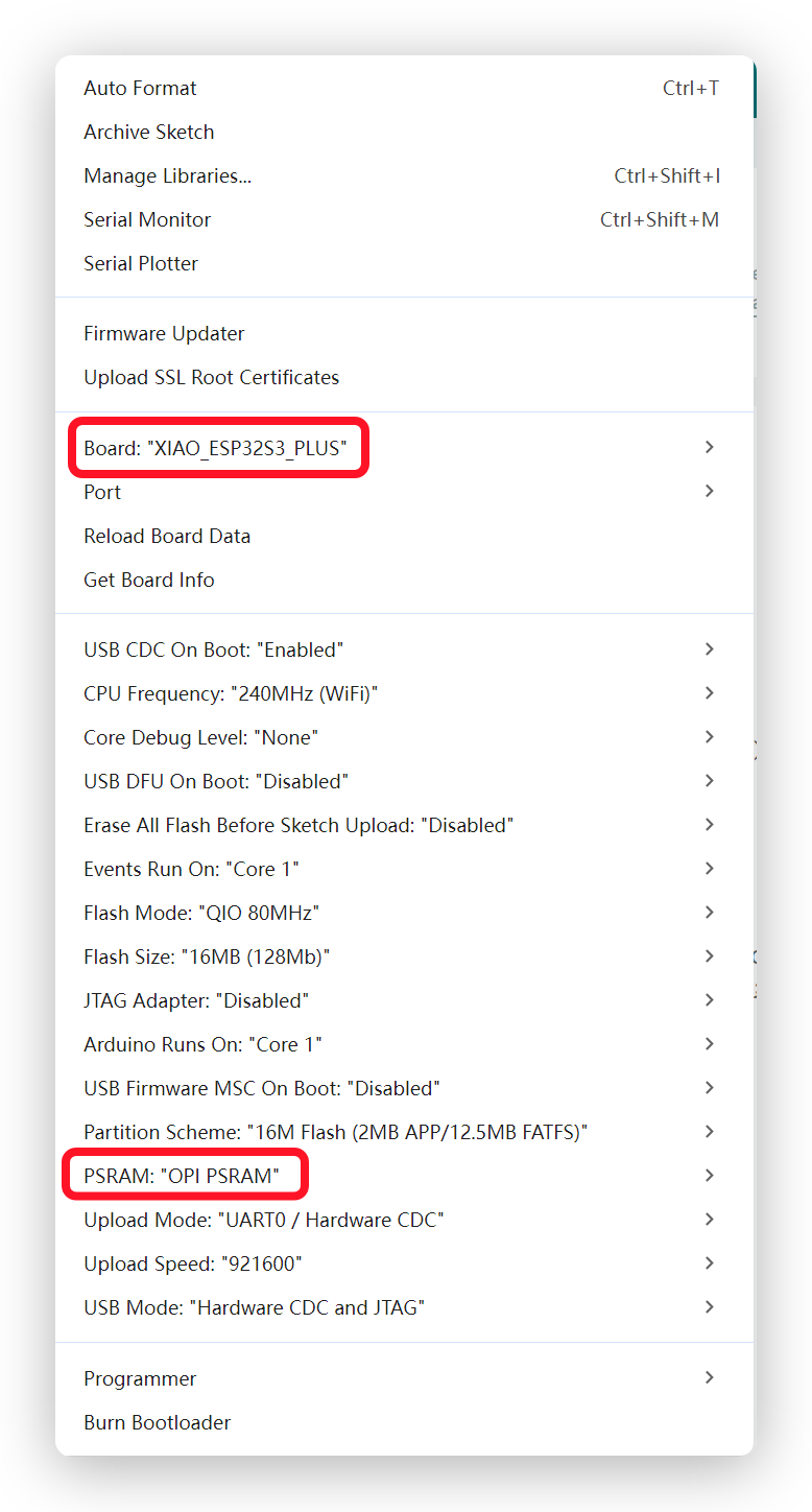
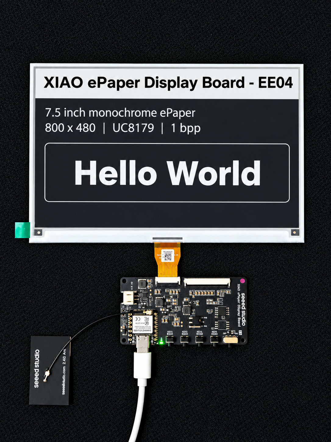
Then click Upload to upload the code. Now you will see the feedback in your epaper screen! Following is the result of the HelloWorld example.
Software Overview
User Buttons on XIAO ePaper Display Board(ESP32-S3) - EE04
This section demonstrates how to read button states and respond to button presses using Arduino. All buttons are active-low, meaning they read LOW when pressed and HIGH when released. Basic Button Reading Example This example demonstrates how to detect button presses and print messages to the serial monitor.
// reTerminal E Series - Button Test
// Based on hardware schematic

// Define button pins according to schematic
const int BUTTON_KEY0 = 2;   // KEY0 - GPIO2
const int BUTTON_KEY1 = 3;   // KEY1 - GPIO3
const int BUTTON_KEY2 = 5;   // KEY2 - GPIO5

// Button state variables
bool lastKey0State = HIGH;
bool lastKey1State = HIGH;
bool lastKey2State = HIGH;

void setup() {
  // Initialize serial communication
  Serial.begin(115200);
  while (!Serial) {
    delay(10); // Wait for serial port to connect
  }

  Serial.println("=================================");
  Serial.println("Press any button to see output");
  Serial.println();

  // Configure button pins as inputs
  // Hardware already has pull-up resistors, so use INPUT mode
  pinMode(BUTTON_KEY0, INPUT_PULLUP);
  pinMode(BUTTON_KEY1, INPUT_PULLUP);
  pinMode(BUTTON_KEY2, INPUT_PULLUP);

  // Read initial states
  lastKey0State = digitalRead(BUTTON_KEY0);
  lastKey1State = digitalRead(BUTTON_KEY1);
  lastKey2State = digitalRead(BUTTON_KEY2);

  Serial.println("Setup complete. Ready to detect button presses...");
}

void loop() {
  // Read current button states
  bool key0State = digitalRead(BUTTON_KEY0);
  bool key1State = digitalRead(BUTTON_KEY1);
  bool key2State = digitalRead(BUTTON_KEY2);

  // Check KEY1
  if (key0State != lastKey0State) {
    if (key0State == LOW) {
      Serial.println("KEY0 (GPIO2) pressed!");
    } else {
      Serial.println("KEY0 (GPIO2) released!");
    }
    lastKey0State = key0State;
    delay(50); // Debounce delay
  }

  // Check KEY2
  if (key1State != lastKey1State) {
    if (key1State == LOW) {
      Serial.println("KEY1 (GPIO3) pressed!");
    } else {
      Serial.println("KEY1 (GPIO3) released!");
    }
    lastKey1State = key1State;
    delay(50); // Debounce delay
  }

  // Check KEY3
  if (key2State != lastKey2State) {
    if (key2State == LOW) {
      Serial.println("KEY2 (GPIO5) pressed!");
    } else {
      Serial.println("KEY2 (GPIO5) released!");
    }
    lastKey2State = key2State;
    delay(50); // Debounce delay
  }

  delay(10); // Small delay to prevent excessive CPU usage
}
User Battery on XIAO ePaper Display Board(ESP32-S3) - EE04
When operating on battery power:
-
The device will automatically enter low-power mode between refreshes
-
Battery life depends on refresh frequency (typically 3-month on a full charge with default settings)
-
The device will display a low battery icon in the top-right corner when the battery level is below 20%
If you want to write some code by yourself to read battery voltage, it will be more precise to add 10ms delay before analogRead() function.
#define VOLTAGE_PIN A0 //GPIO1
#define ADC_ENABLE_PIN A5 //GPIO6

void setup() {
  Serial.begin(115200);
  delay(10);

  pinMode(VOLTAGE_PIN, INPUT);
  pinMode(ADC_ENABLE_PIN, OUTPUT);
  digitalWrite(ADC_ENABLE_PIN , HIGH);
}


void loop() {
  analogReadResolution(12);
  int adcValue = analogRead(VOLTAGE_PIN);
  float voltage = (adcValue / 4096.0) *7.16;
  Serial.print("ADC Value: ");
  Serial.print(adcValue);
  Serial.print(" Voltage: ");
  Serial.print(voltage, 3);
  Serial.println(" V");
  delay(10);
}
Resources
- [PDF] Seeed Studio XIAO ePaper Display EE04 Schematic
- [PDF] Seeed Studio XIAO ePaper Display EE04 Grabcad 3D File
- [ZIP] Seeed Studio XIAO ePaper Display EE04 SCH&PCB
Tech Support & Product Discussion
Thank you for choosing our products! We are here to provide you with different support to ensure that your experience with our products is as smooth as possible. We offer several communication channels to cater to different preferences and needs.