Shield CAN BUS FD de 2 Canales para Raspberry Pi

Este es un shield CAN BUS para Raspberry Pi (en adelante denominado hat pi de 2 canales), E/S CAN BUS de 2 canales, compatible con CAN FD. CAN FD soporta velocidades de transmisión mucho más rápidas (hasta 8Mbps)
También tiene dos resistencias terminadoras de 120Ω integradas que son controladas por los interruptores.

Declaración de Versiones
Hay 3 versiones del shield CAN BUS para Raspberry Pi. Las 3 versiones funcionan perfectamente en la plataforma Raspberry Pi, y puedes omitir esta sección si estás usando la plataforma RPi.
El shield CAN BUS ahora solo soporta el Jetson Nano Developer Kit (tarjeta SD) y no soporta Jetson Nano con eMMC (reComputer J1010/J1020v2). Las diferentes versiones del Shield CAN BUS sí afectan la funcionalidad, por favor revisa cuidadosamente la tabla a continuación si estás usando con la plataforma Jetson Nano.
| Nombre del Producto | Chip | Estado RPi | Estado Jetson Nano |
|---|---|---|---|
| Shield CAN-BUS(FD) de 2 Canales para RPi (MCP2517FD) | MCP2517FD | Dos Canales | Canal Único(can0) |
| Shield CAN-BUS(FD) de 2 Canales para Raspberry Pi (MCP2518FD) | MCP2518FD | Dos Canales | Dos Canales |
Como puedes ver, hay dos versiones de chips utilizados en el 2-Channel CAN-BUS(FD) Shield para RPi (MCP2517FD) y ambos canales funcionan en RPi pero solo un canal (CAN0) funciona en la plataforma Jetson Nano!
Características
- Alta velocidad de transferencia: 8Mbps@10m cable blindado 20AWG / 1Mbps@40m cable blindado 20AWG
- Suministro de energía estable, seleccionable suministro de energía Raspberry Pi o suministro de energía DC
- Compatible con Raspberry Pi 2, Raspberry Pi 3, Raspberry Pi 3, Raspberry Pi 4 y Raspberry Pi Zero
- Configuración de un botón de resistor terminador de 120Ω
- Soporte CAN FD
Descripción General del Hardware


Guía de Montaje

Puedes ver que utilizamos columnas de nylon durante el ensamblaje para evitar cortocircuitos entre los terminales metálicos bajo el puerto CAN BUS y la interfaz HDMI en la Raspberry Pi. Por lo tanto, asegúrate de ensamblar la columna de nylon como se muestra.
Especificaciones
| Parámetro | Valor |
|---|---|
| Entrada de Energía | 12V~24V DC Raspberry Pi GPIO 5V |
| Controlador CAN FD | MCP2517FD |
| Transceptor CAN FD | MCP2557FD |
| Canal CAN FD | 2 |
| Velocidad de Transferencia | 8Mbps@10m cable blindado 20AWG 1Mbps@40m cable blindado 20AWG |
| Interfaz de Comunicación con Pi | SPI |
| Interfaz Grove | Grove I2C x2 |
Plataformas Compatibles
| Arduino | Raspberry Pi | |||
|---|---|---|---|---|
Comenzando
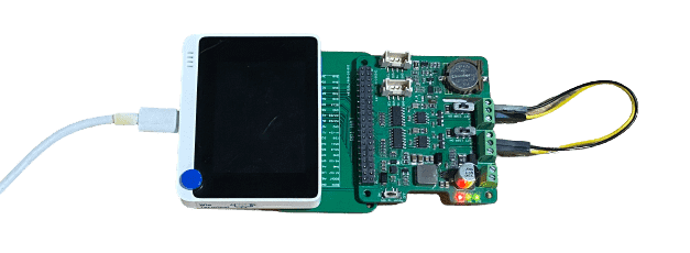
Materiales requeridos
| Raspberry pi | 2-Channel CAN-BUS(FD) Shield | Arduino Board | CAN-BUS Shield V2 |
|---|---|---|---|
 |  |  |  |
| Obtener UNO Ahora | Obtener UNO Ahora | Obtener UNO Ahora | Obtener UNO Ahora |
💡 Nota: El 2 Channel CAN BUS FD Shield para Pi solo es compatible con la versión de kernel 6.6.42 e inferiores.
También necesitamos dos cables puente macho a macho y cables de alimentación para alimentar esas placas.
Conexión de Hardware
-
Paso 1. Sigue la Guía de Montaje para conectar el 2-Channel CAN-BUS(FD) Shield en la Raspberry.
-
Paso 2. Conecta el CAN BUS Shield V2 en la placa Seeeduino (o Arduino)
-
Paso 3. Usa los puentes para conectar el terminal CAN de ambos shields.
| 2-Channel CAN-BUS(FD) Shield | CAN-BUS Shield V2 |
|---|---|
| CAN_0_L | CANL |
| CAN_0_H | CANH |
Puedes encontrar la serigrafía en la parte posterior del shield.
- Paso 4. Alimenta la Raspberry Pi y el Seeeduino.

Software
Instalar CAN-HAT
- Paso 1. Abre el archivo config.txt
sudo nano /boot/config.txt
- Paso 2. Añade la siguiente línea al final del archivo
dtoverlay=seeed-can-fd-hat-v2
-
Paso 3. Presiona Ctrl + x, presiona y y presiona Enter para guardar el archivo
-
Paso 4. Reinicia Raspberry Pi
sudo reboot
- Paso 5. Verifica el registro del kernel para ver si el CAN-BUS HAT se inicializó correctamente. También verás que can0 y can1 aparecen en la lista de resultados de ifconfig
pi@raspberrypi:~ $ dmesg | grep spi
[    6.178008] mcp25xxfd spi0.0 can0: MCP2517FD rev0.0 (-RX_INT +MAB_NO_WARN +CRC_REG +CRC_RX +CRC_TX +ECC -HD m:20.00MHz r:18.50MHz e:0.00MHz) successfully initialized.
[    6.218466] mcp25xxfd spi0.1 (unnamed net_device) (uninitialized): Failed to detect MCP25xxFD (osc=0x00000000).

pi@raspberrypi:~ $ ifconfig -a
can0: flags=128<NOARP>  mtu 16
        unspec 00-00-00-00-00-00-00-00-00-00-00-00-00-00-00-00  txqueuelen 10  (UNSPEC)
        RX packets 0  bytes 0 (0.0 B)
        RX errors 0  dropped 0  overruns 0  frame 0
        TX packets 0  bytes 0 (0.0 B)
        TX errors 0  dropped 0 overruns 0  carrier 0  collisions 0
        device interrupt 166

can1: flags=128<NOARP>  mtu 16
        unspec 00-00-00-00-00-00-00-00-00-00-00-00-00-00-00-00  txqueuelen 10  (UNSPEC)
        RX packets 0  bytes 0 (0.0 B)
        RX errors 0  dropped 0  overruns 0  frame 0
        TX packets 0  bytes 0 (0.0 B)
        TX errors 0  dropped 0 overruns 0  carrier 0  collisions 0
        device interrupt 167

eth0: flags=4163<UP,BROADCAST,RUNNING,MULTICAST>  mtu 1500
        inet 10.0.0.13  netmask 255.255.255.0  broadcast 10.0.0.255
        inet6 fe80::44cc:eeb8:47a0:7fce  prefixlen 64  scopeid 0x20<link>
        ether b8:27:eb:25:d4:e0  txqueuelen 1000  (Ethernet)
        RX packets 299  bytes 27437 (26.7 KiB)
        RX errors 0  dropped 0  overruns 0  frame 0
        TX packets 172  bytes 25974 (25.3 KiB)
        TX errors 0  dropped 0 overruns 0  carrier 0  collisions 0

lo: flags=73<UP,LOOPBACK,RUNNING>  mtu 65536
        inet 127.0.0.1  netmask 255.0.0.0
        inet6 ::1  prefixlen 128  scopeid 0x10<host>
        loop  txqueuelen 1000  (Local Loopback)
        RX packets 0  bytes 0 (0.0 B)
        RX errors 0  dropped 0  overruns 0  frame 0
        TX packets 0  bytes 0 (0.0 B)
        TX errors 0  dropped 0 overruns 0  carrier 0  collisions 0

wlan0: flags=4098<BROADCAST,MULTICAST>  mtu 1500
        ether b8:27:eb:70:81:b5  txqueuelen 1000  (Ethernet)
        RX packets 0  bytes 0 (0.0 B)
        RX errors 0  dropped 0  overruns 0  frame 0
        TX packets 0  bytes 0 (0.0 B)
        TX errors 0  dropped 0 overruns 0  carrier 0  collisions 0
- Paso 6. Configura el protocolo can fd, y el dbitrate puede establecerse a velocidad 8M. Consulta la documentación del kernel para más usos
sudo ip link set can0 up type can bitrate 1000000   dbitrate 8000000 restart-ms 1000 berr-reporting on fd on
sudo ip link set can1 up type can bitrate 1000000   dbitrate 8000000 restart-ms 1000 berr-reporting on fd on

sudo ifconfig can0 txqueuelen 65536
sudo ifconfig can1 txqueuelen 65536
- Paso 7. Abre dos ventanas de terminal e introduce los siguientes comandos en Windows para probar el protocolo can fd.
#send data
cangen can0 -mv
#dump data
candump can0
Puedes probar el CAN-BUS conectando dos canales entre sí usando jumpers: 0_L <===> 1_L, 0_H <===> 1_H.
Comunicar con Arduino CAN BUS Shield
En esta demostración, solo usamos uno de los dos canales.
Para Arduino CAN BUS Shield, proporcionamos el código de Arduino, si no sabes cómo usar Arduino, por favor revisa aquí.
Para el hat de pi de 2 canales, hay dos formas de enviar y recibir, puedes usar tanto can-util/cangen como código python.
CAN BUS Shield envía y CAN HAT recibe
Código de Arduino para CAN BUS Shield:
// demo: CAN-BUS Shield, send data
// [email protected]

#include <mcp_can.h>
#include <SPI.h>

// the cs pin of the version after v1.1 is default to D9
// v0.9b and v1.0 is default D10
const int SPI_CS_PIN = 9;

MCP_CAN CAN(SPI_CS_PIN);                                    // Set CS pin

void setup()
{
    Serial.begin(115200);

    while (CAN_OK != CAN.begin(CAN_500KBPS))              // init can bus : baudrate = 500k
    {
        Serial.println("CAN BUS Shield init fail");
        Serial.println(" Init CAN BUS Shield again");
        delay(100);
    }
    Serial.println("CAN BUS Shield init ok!");
}

unsigned char stmp[8] = {0, 0, 0, 0, 0, 0, 0, 0};
void loop()
{
    //send data:  id = 0x00, standrad frame, data len = 8, stmp: data buf
    stmp[7] = stmp[7]+1;
    if(stmp[7] == 100)
    {
        stmp[7] = 0;
        stmp[6] = stmp[6] + 1;

        if(stmp[6] == 100)
        {
            stmp[6] = 0;
            stmp[5] = stmp[6] + 1;
        }
    }

    CAN.sendMsgBuf(0x00, 0, 8, stmp);
    delay(100);                       // send data per 100ms
}
// END FILE
Configuración de Raspberry pi y puedes usar can-util para recibir
#set 500k baudrate
pi@raspberrypi:~ $ sudo ip link set can0 up type can bitrate 500000
pi@raspberrypi:~ $ ip -details link show can0
3: can0: <NOARP,UP,LOWER_UP,ECHO> mtu 16 qdisc pfifo_fast state UNKNOWN mode DEFAULT group default qlen 10
    link/can  promiscuity 0
    can state ERROR-ACTIVE (berr-counter tx 0 rx 0) restart-ms 0
   bitrate 500000 sample-point 0.875
   tq 25 prop-seg 34 phase-seg1 35 phase-seg2 10 sjw 1
   mcp25xxfd: tseg1 2..256 tseg2 1..128 sjw 1..128 brp 1..256 brp-inc 1
   mcp25xxfd: dtseg1 1..32 dtseg2 1..16 dsjw 1..16 dbrp 1..256 dbrp-inc 1
   clock 40000000numtxqueues 1 numrxqueues 1 gso_max_size 65536 gso_max_segs 65535
#receive
pi@raspberrypi:~ $ candump can0
  can0  000   [8]  00 00 00 00 00 00 00 05
  can0  000   [8]  00 00 00 00 00 00 00 06
  can0  000   [8]  00 00 00 00 00 00 00 07
  can0  000   [8]  00 00 00 00 00 00 00 08
  can0  000   [8]  00 00 00 00 00 00 00 09
  can0  000   [8]  00 00 00 00 00 00 00 0A
  can0  000   [8]  00 00 00 00 00 00 00 0B
  can0  000   [8]  00 00 00 00 00 00 00 0C
  can0  000   [8]  00 00 00 00 00 00 00 0D
  can0  000   [8]  00 00 00 00 00 00 00 0E
  can0  000   [8]  00 00 00 00 00 00 00 0F
  can0  000   [8]  00 00 00 00 00 00 00 10
  can0  000   [8]  00 00 00 00 00 00 00 11
  can0  000   [8]  00 00 00 00 00 00 00 12
  can0  000   [8]  00 00 00 00 00 00 00 13
  can0  000   [8]  00 00 00 00 00 00 00 14
  can0  000   [8]  00 00 00 00 00 00 00 15
  can0  000   [8]  00 00 00 00 00 00 00 16
  can0  000   [8]  00 00 00 00 00 00 00 17
  can0  000   [8]  00 00 00 00 00 00 00 18
  can0  000   [8]  00 00 00 00 00 00 00 19
  can0  000   [8]  00 00 00 00 00 00 00 1A
  can0  000   [8]  00 00 00 00 00 00 00 1B
  can0  000   [8]  00 00 00 00 00 00 00 1C
  can0  000   [8]  00 00 00 00 00 00 00 1D
O puedes usar código python para obtener los datos CAN. Para usar python para recibir datos CAN, debes instalar python-can primero.
# install python-can
sudo pip3 install python-can
Abre un nuevo archivo de python y copia el siguiente código, guárdalo como can_test.py:
import can

can_interface = 'can0'
bus = can.interface.Bus(can_interface, bustype='socketcan_native')
while True:
    message = bus.recv(1.0) # Timeout in seconds.
    if message is None:
            print('Timeout occurred, no message.')
    print(message)
Ejecuta el código Python y los resultados son los siguientes:
pi@raspberrypi:~ $ python3 can_test.py
Timestamp: 1550471771.628215        ID: 0000    S                DLC:  8    00 00 00 00 00 00 0e 63     Channel: can0
Timestamp: 1550471772.629302        ID: 0000    S                DLC:  8    00 00 00 00 00 00 0f 00     Channel: can0
Timestamp: 1550471773.630658        ID: 0000    S                DLC:  8    00 00 00 00 00 00 0f 01     Channel: can0
Timestamp: 1550471774.632018        ID: 0000    S                DLC:  8    00 00 00 00 00 00 0f 02     Channel: can0
Timestamp: 1550471775.633395        ID: 0000    S                DLC:  8    00 00 00 00 00 00 0f 03     Channel: can0
Timestamp: 1550471776.634774        ID: 0000    S                DLC:  8    00 00 00 00 00 00 0f 04     Channel: can0
Timestamp: 1550471777.636135        ID: 0000    S                DLC:  8    00 00 00 00 00 00 0f 05     Channel: can0
Timestamp: 1550471778.637481        ID: 0000    S                DLC:  8    00 00 00 00 00 00 0f 06     Channel: can0
Timestamp: 1550471779.638859        ID: 0000    S                DLC:  8    00 00 00 00 00 00 0f 07     Channel: can0
Timestamp: 1550471780.640222        ID: 0000    S                DLC:  8    00 00 00 00 00 00 0f 08     Channel: can0
Timestamp: 1550471781.641602        ID: 0000    S                DLC:  8    00 00 00 00 00 00 0f 09     Channel: can0
Timestamp: 1550471782.642970        ID: 0000    S                DLC:  8    00 00 00 00 00 00 0f 0a     Channel: can0
CAN BUS Shield recibe y CAN HAT envía
Para Raspberry Pi, puedes usar cangen para enviar paquetes aleatorios:
pi@raspberrypi:~ $ cangen can0 -v
  can0  442#14.C4.1A.1A.C2.25.79.25
  can0  748#4E.C7.8B.0B.6E.B9.15.77
  can0  1E4#64.D4.62.22.2F.A6.BF
  can0  1DD#69.6F.61.33.1F.59.E4.7C
  can0  63D#
  can0  764#2C.C1.E3
  can0  68B#11.9C.63.6D.EA.E9.4B
  can0  329#DA.06.2C.34.6C
  can0  7DD#2E.F5.E0.2A.26.77.58.38
  can0  1BE#94.30.6E.2F.A2.7B.E3.1D
  can0  654#D1.21.A3.58.31.E8.51.5F
  can0  706#51.41.36.5C.43.8D.AE.5D
  can0  34A#89.F2.DE.33.AE.52.38.6C
  can0  6AC#C1.35.83.41.37
  can0  38C#22.AF
  can0  208#22.8E.97.58.E5.69.F7.2C
Para Arduino, puedes usar el siguiente código para recibir datos CAN.
// demo: CAN-BUS Shield, receive data with interrupt mode
// when in interrupt mode, the data coming can't be too fast, must >20ms, or else you can use check mode
// loovee, 2014-6-13

#include <SPI.h>
#include "mcp_can.h"

// the cs pin of the version after v1.1 is default to D9
// v0.9b and v1.0 is default D10
const int SPI_CS_PIN = 9;

MCP_CAN CAN(SPI_CS_PIN);                                    // Set CS pin


unsigned char flagRecv = 0;
unsigned char len = 0;
unsigned char buf[8];
char str[20];

void setup()
{
    Serial.begin(115200);

    while (CAN_OK != CAN.begin(CAN_500KBPS))              // init can bus : baudrate = 500k
    {
        Serial.println("CAN BUS Shield init fail");
        Serial.println(" Init CAN BUS Shield again");
        delay(100);
    }
    Serial.println("CAN BUS Shield init ok!");

    attachInterrupt(0, MCP2515_ISR, FALLING); // start interrupt
}

void MCP2515_ISR()
{
    flagRecv = 1;
}

void loop()
{
    if(flagRecv)
    {                                   // check if get data

        flagRecv = 0;                   // clear flag

        // iterate over all pending messages
        // If either the bus is saturated or the MCU is busy,
        // both RX buffers may be in use and reading a single
        // message does not clear the IRQ conditon.
        while (CAN_MSGAVAIL == CAN.checkReceive())
        {
            // read data,  len: data length, buf: data buf
            CAN.readMsgBuf(&len, buf);

            // print the data
            for(int i = 0; i<len; i++)
            {
                Serial.print(buf[i]);Serial.print("\t");
            }
            Serial.println();
        }
    }
}
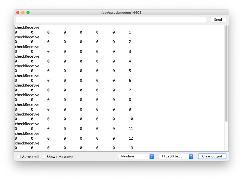
Abre el Monitor Serie del IDE de Arduino haciendo clic en Herramientas-> Monitor Serie. O presiona las teclas ctrl+shift+m al mismo tiempo. Establece la velocidad de baudios a 115200. El resultado debería ser como:

O puedes usar python-can para enviar datos:
El código Python es el siguiente:
import time
import can

bustype = 'socketcan_native'
channel = 'can0'

def producer(id):
    """:param id: Spam the bus with messages including the data id."""
    bus = can.interface.Bus(channel=channel, bustype=bustype)
    for i in range(10):
        msg = can.Message(arbitration_id=0xc0ffee, data=[id, i, 0, 1, 3, 1, 4, 1], extended_id=False)
        bus.send(msg)
    # Issue #3: Need to keep running to ensure the writing threads stay alive. ?
    time.sleep(1)

producer(10)
desinstalar CAN-HAT
Si deseas desinstalar este CAN-HAT, simplemente ejecuta el siguiente código:
pi@raspberrypi:~/seeed-linux-dtoverlays/modules/CAN-HAT $ sudo ./uninstall.sh
...
------------------------------------------------------
Please reboot your raspberry pi to apply all settings
Thank you!
------------------------------------------------------
Usando CAN-BUS Shield con Jetson Nano
Ahora el CAN-BUS Shield también es compatible con la plataforma Jetson Nano, pero existen algunas limitaciones basadas en diferentes versiones de hardware. ¡Por favor consulta la Declaración de Versión si estás usando la plataforma Jetson Nano!
- Clona el Repositorio:
git clone https://github.com/Seeed-Studio/seeed-linux-dtoverlays
- Construir dtbo y controlador:
cd seeed-linux-dtoverlays
export CUSTOM_MOD_LIST="CAN-HAT"; make all_jetsonnano
- Instalar el Controlador:
sudo -E make install_jetsonnano
- Instalar dtbo:
sudo cp overlays/jetsonnano/2xMCP2518FD-spi0.dtbo /boot
sudo /opt/nvidia/jetson-io/config-by-hardware.py -n "Seeed 2xMCP2518FD"
sudo reboot
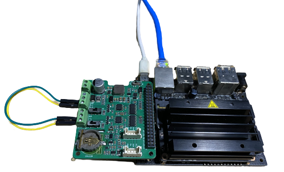
Ahora también puedes ejecutar dmesg | grep spi e ifconfig -a para verificar si el CAN-BUS se inicializó correctamente. Dependiendo de tu hardware, deberías poder ver can0 o tanto can0 como can1.
El hardware utilizado aquí es el último 2-Channel CAN FD Master Hat para RPi que soporta dos canales en la Plataforma Jetson Nano, si tienes versiones anteriores entonces solo tendrás un canal único can0.
qqq@jetson-qqq:~$ dmesg | grep spi
[   10.867712] mcp25xxfd spi0.0 can0: MCP2518FD rev0.0 (-RX_INT -MAB_NO_WARN +CRC_REG +CRC_RX +CRC_TX +ECC -HD m:20.00MHz r:18.50MHz e:0.00MHz) successfully initialized.
[   10.879487] mcp25xxfd spi0.1 can1: MCP2518FD rev0.0 (-RX_INT -MAB_NO_WARN +CRC_REG +CRC_RX +CRC_TX +ECC -HD m:20.00MHz r:18.50MHz e:0.00MHz) successfully initialized.

qqq@jetson-qqq:~$ ifconfig -a
can0: flags=128<NOARP>  mtu 16
        unspec 00-00-00-00-00-00-00-00-00-00-00-00-00-00-00-00  txqueuelen 10  (UNSPEC)
        RX packets 0  bytes 0 (0.0 B)
        RX errors 0  dropped 0  overruns 0  frame 0
        TX packets 0  bytes 0 (0.0 B)
        TX errors 0  dropped 0 overruns 0  carrier 0  collisions 0
        device interrupt 112

can1: flags=128<NOARP>  mtu 16
        unspec 00-00-00-00-00-00-00-00-00-00-00-00-00-00-00-00  txqueuelen 10  (UNSPEC)
        RX packets 0  bytes 0 (0.0 B)
        RX errors 0  dropped 0  overruns 0  frame 0
        TX packets 0  bytes 0 (0.0 B)
        TX errors 0  dropped 0 overruns 0  carrier 0  collisions 0
        device interrupt 114
Pruebas
NOTA: Usando 2-Channel CAN FD Master Hat for RPi como hardware aquí.
También puedes conectar los canales de la siguiente manera para probar:
0_L <===> 1_L
0_H <===> 1_H
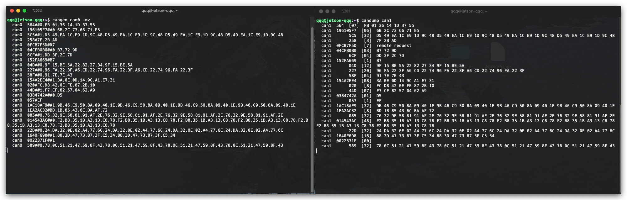
Abre dos ventanas de terminal e ingresa los siguientes comandos en las ventanas para probar el protocolo can fd.
#send data
cangen can0 -mv
#dump data
candump can1
Uso del RTC Integrado
El último 2-Channel CAN FD Master Hat para RPi también tiene un RTC integrado. Sigue estos pasos para instalar los controladores del RTC en Raspberry Pi:
- Actualiza Raspberry Pi y Reinicia:
sudo apt update
sudo apt upgrade
sudo reboot
- Instsall Dependencies
sudo apt install i2c-tools build-essential raspberrypi-kernel-headers
- Descargar el controlador:
curl -O -L https://github.com/dresden-elektronik/raspbee2-rtc/archive/master.zip
unzip master.zip
- Compila el módulo del kernel RTC
cd raspbee2-rtc-master
make
- Instalar el módulo del kernel RTC
sudo make install
sudo reboot
- Configurar la hora del sistema al módulo RTC
sudo hwclock --systohc
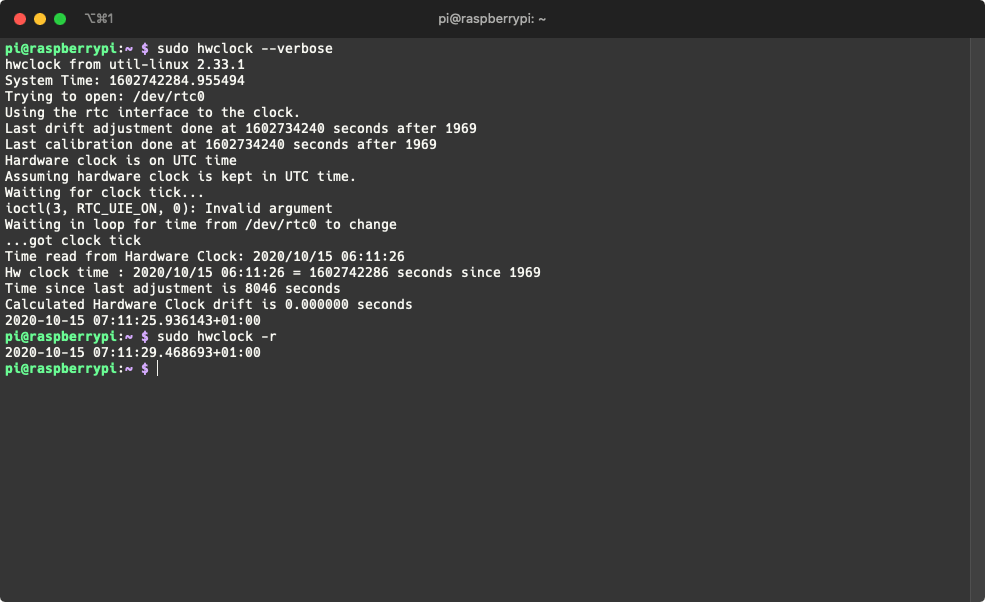
- Prueba que el RTC está funcionando
sudo hwclock --verbose
Ahora puedes leer la hora del RTC usando el siguiente comando:
sudo hwclock -r
Uso con Wio Terminal
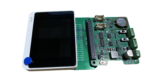
Además de usar el CAN-BUS Pi Hat con SBCs, ahora también puedes usarlo con el Wio Terminal (Placa Compatible con Arduino)! ¡Y desarrollar proyectos relacionados con CAN en MCU!
Por favor revisa las siguientes wikis para obtener más información sobre Wio Terminal:
Hardware Requerido
-
Placa Adaptadora de Hat de Raspberry Pi de 40 Pines Para Wio Terminal
-
Shield CAN-BUS(FD) de 2 Canales para Raspberry Pi (MCP2518FD)
Para propósitos de prueba, también puedes preparar algunos otros componentes de desarrollo CAN-BUS, para este ejemplo estamos usando los siguientes:
- CAN-BUS Shield V2 adopta MCP2515 y MCP2551 + Placa Arduino
Instalar la Librería Arduino Seeed_Arduino_CAN
¡Por favor asegúrate de haber instalado la librería Seeed SAMD Board y actualizado a la última versión!
-
Visita los repositorios Seeed_Arduino_CAN y descarga todo el repositorio a tu unidad local.
-
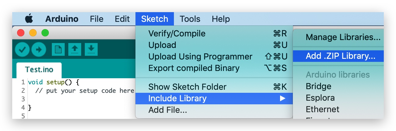
Ahora, la librería Seeed_Arduino_CAN puede ser instalada en el Arduino IDE. Abre el Arduino IDE, y haz clic en
sketch->Include Library->Add .ZIP Library, y elige el archivoSeeed_Arduino_CANque acabas de descargar.
Código de Ejemplo de Envío
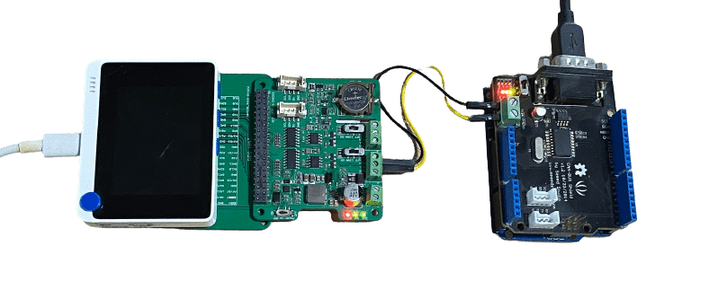
Este es un ejemplo de usar el Shield CAN-BUS(FD) de 2 Canales para Raspberry Pi (MCP2518FD) con Wio Terminal para enviar datos CAN-BUS a otro dispositivo CAN-BUS (En este caso, es CAN-BUS Shield V2 adopta MCP2515 y MCP2551 + Arduino Uno)
Conexión de Hardware
-
Conecta Shield CAN-BUS(FD) de 2 Canales para Raspberry Pi (MCP2518FD)'s
Channel 0 L-> CAN-BUS Shield V2'sCANL -
Conecta Shield CAN-BUS(FD) de 2 Canales para Raspberry Pi (MCP2518FD)'s
Channel 0 H-> CAN-BUS Shield V2'sCANH -
Conecta Shield CAN-BUS(FD) de 2 Canales para Raspberry Pi (MCP2518FD) con Wio Terminal usando Placa Adaptadora de Hat de Raspberry Pi de 40 Pines Para Wio Terminal.
- Código para Arduino Uno + CAN-BUS Shield V2
#include <SPI.h>
#include "mcp2515_can.h"

/*SAMD core*/
#ifdef ARDUINO_SAMD_VARIANT_COMPLIANCE
    #define SERIAL SerialUSB
#else
    #define SERIAL Serial
#endif

const int SPI_CS_PIN = 9;
mcp2515_can CAN(SPI_CS_PIN);

unsigned char len = 0;
unsigned char buf[8];

void setup() {
    SERIAL.begin(115200);
    while (!SERIAL) {
        ; // wait for serial port to connect. Needed for native USB port only
    }
    while (CAN_OK != CAN.begin(CAN_500KBPS)) {             // init can bus : baudrate = 500k
        // init can bus : baudrate = 500k
        SERIAL.println("CAN BUS Shield init fail");
        SERIAL.println(" Init CAN BUS Shield again");
        delay(100);
    }
    SERIAL.println("CAN BUS Shield init ok!");
}

void loop() {
        // iterate over all pending messages
        // If either the bus is saturated or the MCU is busy,
        // both RX buffers may be in use and reading a single
        // message does not clear the IRQ conditon.
        while (CAN_MSGAVAIL == CAN.checkReceive()) {
            // read data,  len: data length, buf: data buf
            SERIAL.println("checkReceive");
            CAN.readMsgBuf(&len, buf);

            // print the data
            for (int i = 0; i < len; i++) {
                SERIAL.print(buf[i]); SERIAL.print("\t");
            }
            SERIAL.println();
        }
}
- Código para Wio Terminal + Shield CAN-BUS(FD) de 2 Canales para Raspberry Pi (MCP2518FD)
#include <SPI.h>
#include "mcp2518fd_can.h"
/*SAMD core*/
#ifdef ARDUINO_SAMD_VARIANT_COMPLIANCE
#define SERIAL SerialUSB
#else
#define SERIAL Serial
#endif
// Set SPI CS Pin according to your hardware
// For Wio Terminal w/ MCP2518FD RPi Hat:
// Channel 0 SPI_CS Pin: BCM 8
// Channel 1 SPI_CS Pin: BCM 7
// Interupt Pin: BCM25
// *****************************************
// For Arduino MCP2515 Hat:
// SPI_CS Pin: D9
const int SPI_CS_PIN = BCM8;
mcp2518fd CAN(SPI_CS_PIN); // Set CS pin
void setup() {
SERIAL.begin(115200);
while(!Serial){};
while (0 != CAN.begin((byte)CAN_500K_1M)) { // init can bus : baudrate = 500k
SERIAL.println("CAN BUS Shield init fail");
SERIAL.println(" Init CAN BUS Shield again");
delay(100);
}
SERIAL.println("CAN BUS Shield init ok!");
}
unsigned char stmp[8] = {0, 0, 0, 0, 0, 0, 0, 0};
void loop() {
// send data: id = 0x00, standrad frame, data len = 8, stmp: data buf
stmp[7] = stmp[7] + 1;
if (stmp[7] == 100) {
stmp[7] = 0;
stmp[6] = stmp[6] + 1;
if (stmp[6] == 100) {
stmp[6] = 0;
stmp[5] = stmp[6] + 1;
}
}
CAN.sendMsgBuf(0x00, 0, 8, stmp);
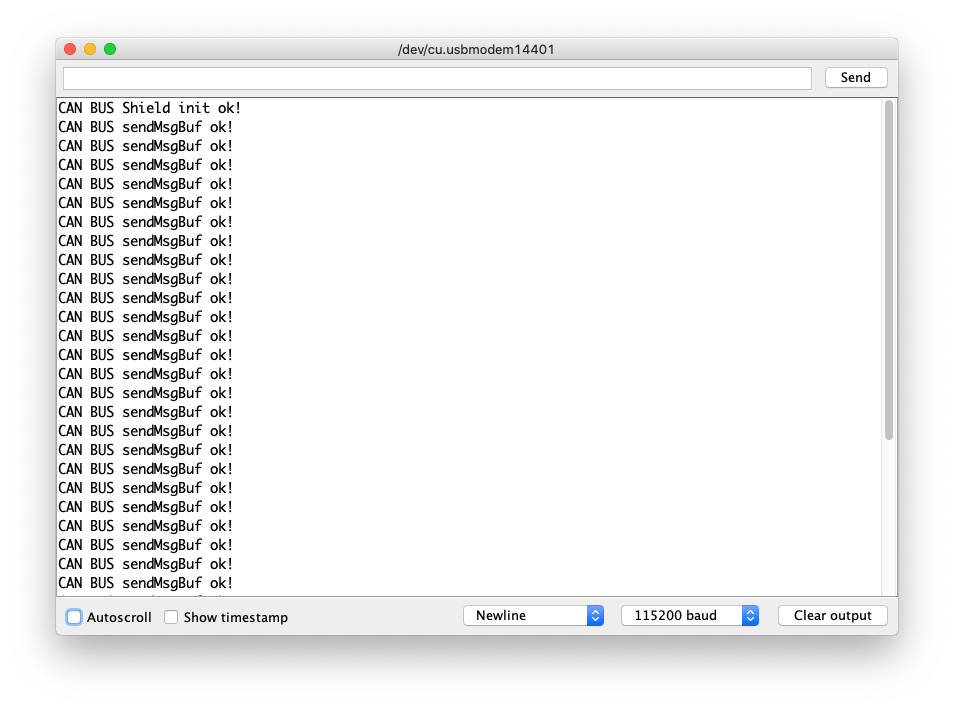
delay(100); // send data per 100ms
SERIAL.println("CAN BUS sendMsgBuf ok!");
}
Código de Ejemplo de Recepción
Este es un ejemplo de uso del Shield CAN-BUS(FD) de 2 Canales para Raspberry Pi (MCP2518FD) con Wio Terminal para recibir datos CAN-BUS de otro dispositivo CAN-BUS (En este caso, es el CAN-BUS Shield V2 que adopta MCP2515 y MCP2551 + Arduino Uno)
Conexión de Hardware
La misma conexión que el Ejemplo de Envío anterior.
- Código para Arduino Uno + CAN-BUS Shield V2
#include <SPI.h>
#include "mcp2515_can.h"

/*SAMD core*/
#ifdef ARDUINO_SAMD_VARIANT_COMPLIANCE
    #define SERIAL SerialUSB
#else
    #define SERIAL Serial
#endif

const int SPI_CS_PIN = 9;
mcp2515_can CAN(SPI_CS_PIN); // Set CS pin


void setup() {
    SERIAL.begin(115200);
    while(!Serial){};

    while (CAN_OK != CAN.begin(CAN_500KBPS)) {             // init can bus : baudrate = 500k
        SERIAL.println("CAN BUS Shield init fail");
        SERIAL.println(" Init CAN BUS Shield again");
        delay(100);
    }
    SERIAL.println("CAN BUS Shield init ok!");
}

unsigned char stmp[8] = {0, 0, 0, 0, 0, 0, 0, 0};
void loop() {
    // send data:  id = 0x00, standrad frame, data len = 8, stmp: data buf
    stmp[7] = stmp[7] + 1;
    if (stmp[7] == 100) {
        stmp[7] = 0;
        stmp[6] = stmp[6] + 1;

        if (stmp[6] == 100) {
            stmp[6] = 0;
            stmp[5] = stmp[6] + 1;
        }
    }

    CAN.sendMsgBuf(0x00, 0, 8, stmp);
    delay(100);                       // send data per 100ms
    SERIAL.println("CAN BUS sendMsgBuf ok!");
}
- Código para Wio Terminal + Shield CAN-BUS(FD) de 2 Canales para Raspberry Pi (MCP2518FD)
#include <SPI.h>
#include "mcp2518fd_can.h"

/*SAMD core*/
#ifdef ARDUINO_SAMD_VARIANT_COMPLIANCE
    #define SERIAL SerialUSB
#else
    #define SERIAL Serial
#endif

// Set SPI CS Pin according to your hardware
// For Wio Terminal w/ MCP2518FD RPi Hat:
// Channel 0 SPI_CS Pin: BCM 8
// Channel 1 SPI_CS Pin: BCM 7
// Interupt Pin: BCM25
// *****************************************
// For Arduino MCP2515 Hat:
// SPI_CS Pin: D9

const int SPI_CS_PIN = BCM8;
mcp2518fd CAN(SPI_CS_PIN);

unsigned char len = 0;
unsigned char buf[8];

void setup() {
    SERIAL.begin(115200);
    while (!SERIAL) {
        ; // wait for serial port to connect. Needed for native USB port only
    }
    while (0 != CAN.begin((byte)CAN_500K_1M)) {            // init can bus : baudrate = 500k
        SERIAL.println("CAN BUS Shield init fail");
        SERIAL.println(" Init CAN BUS Shield again");
        delay(100);
    }
    SERIAL.println("CAN BUS Shield init ok!");
}

void loop() {
        // iterate over all pending messages
        // If either the bus is saturated or the MCU is busy,
        // both RX buffers may be in use and reading a single
        // message does not clear the IRQ conditon.
        while (CAN_MSGAVAIL == CAN.checkReceive()) {
            // read data,  len: data length, buf: data buf
            SERIAL.println("checkReceive");
            CAN.readMsgBuf(&len, buf);

            // print the data
            for (int i = 0; i < len; i++) {
                SERIAL.print(buf[i]); SERIAL.print("\t");
            }
            SERIAL.println();
        }
}
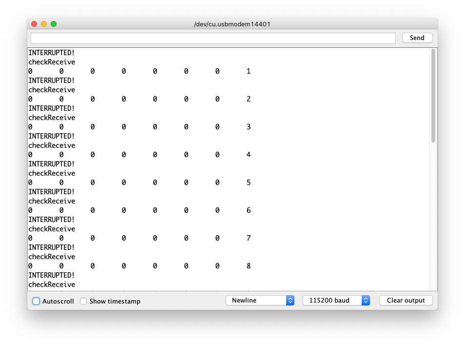
Código de Ejemplo de Recepción usando Interrupción
Este es un ejemplo de uso del Shield CAN-BUS(FD) de 2 Canales para Raspberry Pi (MCP2518FD) con Wio Terminal para recibir datos CAN-BUS de otro dispositivo CAN-BUS (En este caso, es el CAN-BUS Shield V2 que adopta MCP2515 y MCP2551 + Arduino Uno). Para hacerlo más confiable, aquí se usó interrupción para activar el flujo de datos entrantes.
Conexión de Hardware
- Código para Arduino Uno + CAN-BUS Shield V2
#include <SPI.h>
#include "mcp2515_can.h"

/*SAMD core*/
#ifdef ARDUINO_SAMD_VARIANT_COMPLIANCE
    #define SERIAL SerialUSB
#else
    #define SERIAL Serial
#endif

const int SPI_CS_PIN = 9;
mcp2515_can CAN(SPI_CS_PIN); // Set CS pin

void setup() {
    SERIAL.begin(115200);
    while(!Serial){};

    while (CAN_OK != CAN.begin(CAN_500KBPS)) {             // init can bus : baudrate = 500k
        SERIAL.println("CAN BUS Shield init fail");
        SERIAL.println(" Init CAN BUS Shield again");
        delay(100);
    }
    SERIAL.println("CAN BUS Shield init ok!");
}

unsigned char stmp[8] = {0, 0, 0, 0, 0, 0, 0, 0};
void loop() {
    // send data:  id = 0x00, standrad frame, data len = 8, stmp: data buf
    stmp[7] = stmp[7] + 1;
    if (stmp[7] == 100) {
        stmp[7] = 0;
        stmp[6] = stmp[6] + 1;

        if (stmp[6] == 100) {
            stmp[6] = 0;
            stmp[5] = stmp[6] + 1;
        }
    }

    CAN.sendMsgBuf(0x00, 0, 8, stmp);
    delay(100);                       // send data per 100ms
    SERIAL.println("CAN BUS sendMsgBuf ok!");
}
Código para Wio Terminal + Shield de 2 Canales CAN-BUS(FD) para Raspberry Pi (MCP2518FD)
#include <SPI.h>
#include "mcp2518fd_can.h"

/*SAMD core*/
#ifdef ARDUINO_SAMD_VARIANT_COMPLIANCE
    #define SERIAL SerialUSB
#else
    #define SERIAL Serial
#endif

// Set SPI CS Pin according to your hardware
// For Wio Terminal w/ MCP2518FD RPi Hat:
// Channel 0 SPI_CS Pin: BCM 8
// Channel 1 SPI_CS Pin: BCM 7
// Interupt Pin: BCM25
// *****************************************
// For Arduino MCP2515 Hat:
// SPI_CS Pin: D9

const int SPI_CS_PIN = BCM8;
const int CAN_INT_PIN = BCM25;

mcp2518fd CAN(SPI_CS_PIN);

unsigned char flagRecv = 0;
unsigned char len = 0;
unsigned char buf[8];

void MCP2515_ISR() {
    Serial.println("INTERUPTED!");
    flagRecv = 1;
}

void setup() {
    SERIAL.begin(115200);
    while (!SERIAL) {
        ; // wait for serial port to connect. Needed for native USB port only
    }
    pinMode(CAN_INT_PIN, INPUT);
    attachInterrupt(digitalPinToInterrupt(CAN_INT_PIN), MCP2515_ISR, FALLING); // start interrupt

    while (0 != CAN.begin((byte)CAN_500K_1M)) {            // init can bus : baudrate = 500k
        SERIAL.println("CAN BUS Shield init fail");
        SERIAL.println(" Init CAN BUS Shield again");
        delay(100);
    }
    SERIAL.println("CAN BUS Shield init ok!");
}

void loop() {
  if (flagRecv) // Triggered Interrupt
  {
    flagRecv = 0;
  // iterate over all pending messages
  // If either the bus is saturated or the MCU is busy,
  // both RX buffers may be in use and reading a single
  // message does not clear the IRQ conditon.
    while (CAN_MSGAVAIL == CAN.checkReceive()) {
        // read data,  len: data length, buf: data buf
      SERIAL.println("checkReceive");
      CAN.readMsgBuf(&len, buf);

        // print the data
      for (int i = 0; i < len; i++) {
        SERIAL.print(buf[i]); SERIAL.print("\t");
        }
      SERIAL.println();
    }
  }
}
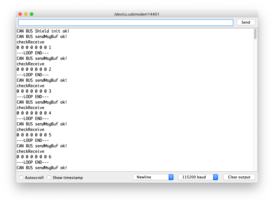
Código de Ejemplo de Auto Envío-Recepción
Este es un ejemplo de envío y recepción de datos CAN-BUS por sí mismo usando el Shield CAN-BUS(FD) de 2 Canales para Raspberry Pi (MCP2518FD).
Conexión de Hardware
-
Conecta el
Canal 0 Ldel Shield CAN-BUS(FD) de 2 Canales para Raspberry Pi (MCP2518FD) ->Canal 1 Ldel Shield CAN-BUS(FD) de 2 Canales para Raspberry Pi (MCP2518FD) -
Conecta el
Canal 0 Hdel Shield CAN-BUS(FD) de 2 Canales para Raspberry Pi (MCP2518FD) ->Canal 1 Hdel Shield CAN-BUS(FD) de 2 Canales para Raspberry Pi (MCP2518FD)
#include <SPI.h>
#include "mcp2518fd_can.h"

/*SAMD core*/
#ifdef ARDUINO_SAMD_VARIANT_COMPLIANCE
    #define SERIAL SerialUSB
#else
    #define SERIAL Serial
#endif

// Set SPI CS Pin according to your hardware
// For Wio Terminal w/ MCP2518FD RPi Hat:
// Channel 0 SPI_CS Pin: BCM 8
// Channel 1 SPI_CS Pin: BCM 7
// Interupt Pin: BCM25
// *****************************************
// For Arduino MCP2515 Hat:
// SPI_CS Pin: D9

const int SPI_CS_PIN_SEND = BCM8;
const int SPI_CS_PIN_RECEIVE = BCM7;

mcp2518fd CAN_SEND(SPI_CS_PIN_SEND);
mcp2518fd CAN_RECEIVE(SPI_CS_PIN_RECEIVE);

unsigned char len = 0;
unsigned char buf[8];

void setup() {
    SERIAL.begin(115200);
    while(!Serial); // wait for Serial

    if (CAN_SEND.begin((byte)CAN_500K_1M) != 0 || CAN_RECEIVE.begin((byte)CAN_500K_1M) != 0) {
      Serial.println("CAN-BUS initiliased error!");
      while(1);
    }

    SERIAL.println("CAN BUS Shield init ok!");
}

unsigned char stmp[8] = {0, 0, 0, 0, 0, 0, 0, 0};
void loop() {
    // send data:  id = 0x00, standrad frame, data len = 8, stmp: data buf
    stmp[7] = stmp[7] + 1;
    if (stmp[7] == 100) {
        stmp[7] = 0;
        stmp[6] = stmp[6] + 1;

        if (stmp[6] == 100) {
            stmp[6] = 0;
            stmp[5] = stmp[6] + 1;
        }
    }

    CAN_SEND.sendMsgBuf(0x00, 0, 8, stmp);
    delay(100);                       // send data per 100ms
    SERIAL.println("CAN BUS sendMsgBuf ok!");

    // ---------------------

    if (CAN_MSGAVAIL == CAN_RECEIVE.checkReceive()) {
    // read data,  len: data length, buf: data buf
      SERIAL.println("checkReceive");
      CAN_RECEIVE.readMsgBuf(&len, buf);
    // print the data
    for (int i = 0; i < len; i++) {
        SERIAL.print(buf[i]); SERIAL.print(" ");
    }
    SERIAL.println();
    }
    SERIAL.println("---LOOP END---");
}
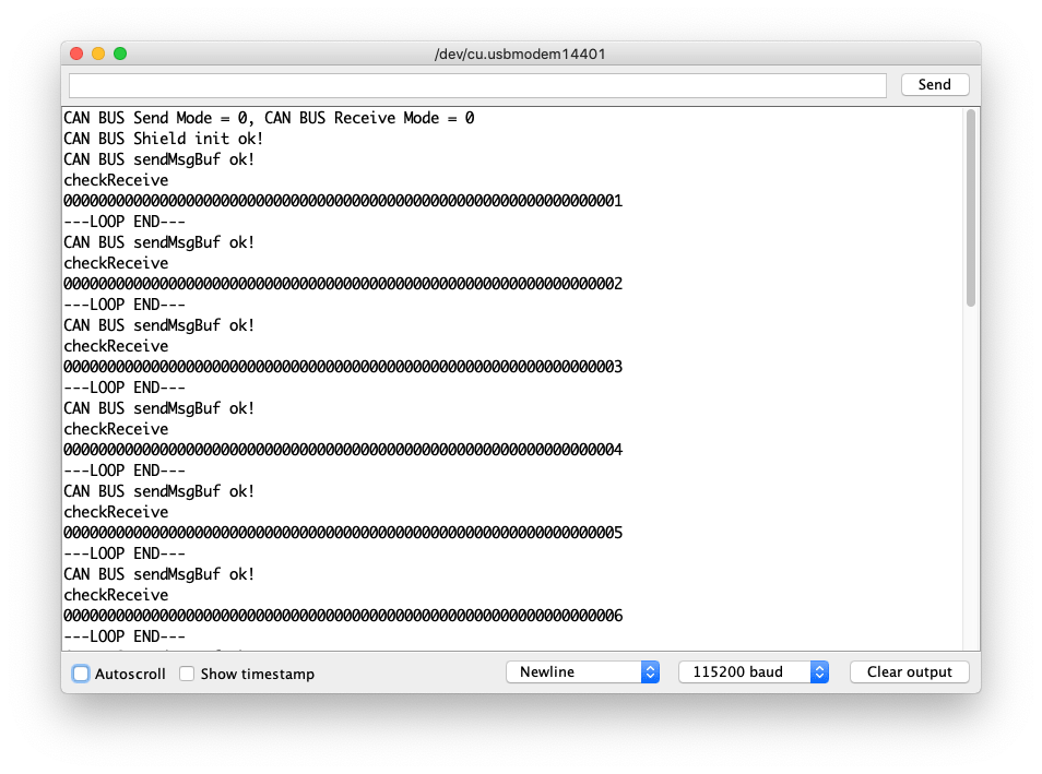
Código de Ejemplo de Envío FD
Este es un ejemplo de envío y recepción de datos CAN-BUS (hasta 64 bits) usando el protocolo FD por sí mismo utilizando el Shield CAN-BUS(FD) de 2 Canales para Raspberry Pi (MCP2518FD).
Conexión de Hardware
La misma conexión que el Ejemplo de Auto Envío-Recepción.
#include <SPI.h>
#include "mcp2518fd_can.h"

/*SAMD core*/
#ifdef ARDUINO_SAMD_VARIANT_COMPLIANCE
    #define SERIAL SerialUSB
#else
    #define SERIAL Serial
#endif

// Set SPI CS Pin according to your hardware
// For Wio Terminal w/ MCP2518FD RPi Hat:
// Channel 0 SPI_CS Pin: BCM 8
// Channel 1 SPI_CS Pin: BCM 7
// Interupt Pin: BCM25
// *****************************************
// For Arduino MCP2515 Hat:
// SPI_CS Pin: D9

const int SPI_CS_PIN_SEND = BCM8;
const int SPI_CS_PIN_RECEIVE = BCM7;

mcp2518fd CAN_SEND(SPI_CS_PIN_SEND);
mcp2518fd CAN_RECEIVE(SPI_CS_PIN_RECEIVE);

void setup() {
    SERIAL.begin(115200);
    while(!Serial); // wait for Serial
    CAN_SEND.setMode(0);
    CAN_RECEIVE.setMode(0);

    if (CAN_SEND.begin((byte)CAN_500K_1M) != 0 || CAN_RECEIVE.begin((byte)CAN_500K_1M) != 0) {
      Serial.println("CAN-BUS initiliased error!");
      while(1);
    }
    byte send_mode = CAN_SEND.getMode();
    byte receive_mode = CAN_RECEIVE.getMode();
    SERIAL.printf("CAN BUS Send Mode = %d, CAN BUS Receive Mode = %d\n\r",send_mode, receive_mode);
    SERIAL.println("CAN BUS Shield init ok!");
}

unsigned char stmp[64] = {0};
unsigned char len = 0;
unsigned char buf[64];

void loop() {
    stmp[63] = stmp[63] + 1;
    if (stmp[63] == 100) {
        stmp[63] = 0;
        stmp[62] = stmp[62] + 1;

        if (stmp[62] == 100) {
            stmp[62] = 0;
            stmp[61] = stmp[62] + 1;
        }
    }

    CAN_SEND.sendMsgBuf(0x00, 0, 15, stmp);
    delay(100);                       // send data per 100ms
    SERIAL.println("CAN BUS sendMsgBuf ok!");

    // ---------------------

    if (CAN_MSGAVAIL == CAN_RECEIVE.checkReceive()) {
    // read data,  len: data length, buf: data buf
      SERIAL.println("checkReceive");
      CAN_RECEIVE.readMsgBuf(&len, buf);
    // print the data
    for (int i = 0; i < len; i++) {
        SERIAL.print(buf[i]); SERIAL.print(" ");
    }
    SERIAL.println();
    }
    SERIAL.println("---LOOP END---");
}
Visor de Esquemas en Línea
Recursos
- [PDF] Esquemas del Shield CAN-BUS(FD) de 2 Canales para Raspberry Pi (MCP2518FD)
- [ZIP] Archivo de esquemas del Shield CAN-BUS(FD) de 2 Canales para Raspberry Pi
- [ZIP] Archivo de esquemas del Hat Maestro CAN FD de 2 Canales para RPi
- [PDF] Hoja de datos del MCP2517
- [PDF] Hoja de datos del MCP2557
Soporte Técnico y Discusión de Productos
¡Gracias por elegir nuestros productos! Estamos aquí para brindarle diferentes tipos de soporte para asegurar que su experiencia con nuestros productos sea lo más fluida posible. Ofrecemos varios canales de comunicación para satisfacer diferentes preferencias y necesidades.