Grove - Acelerómetro y Brújula de 6 Ejes V2.0

El Grove –Acelerómetro y Brújula de 6 Ejes V2.0 es un acelerómetro de 3 ejes combinado con un sensor magnético de 3 ejes. Es una versión mejorada del Grove - Acelerómetro y Brújula de 6 Ejes V1.0 y está basado en el módulo sensor LSM303D que tiene un rango de escala completa de aceleración lineal seleccionable de ±2g / ±4g / ±8g / ±16g y un rango de escala completa de campo magnético seleccionable de ±2 /±4 / ±8 / ±12 gauss. Tanto las partes magnéticas como las partes del acelerómetro pueden ser apagadas por separado para reducir el consumo de energía. El Arduino puede obtener estos datos a través de la interfaz I2C con la biblioteca proporcionada para este módulo.

Especificaciones
- Voltaje de Entrada: 5V
- Interfaz I2C e interfaz SPI seleccionable
- Escala de medición seleccionable
- Detección de orientación 6D
- 2 generadores de interrupción programables independientes
- Modo de apagado
- Dirección I2C 0x1E(predeterminada), o 0x1D
Si deseas usar múltiples dispositivos I2C, por favor consulta Software I2C.
Más detalles sobre los módulos Grove por favor consulta Sistema Grove
Plataformas Soportadas
| Arduino | Raspberry Pi |
|---|---|
|
|
Las plataformas mencionadas anteriormente como compatibles son una indicación de la compatibilidad de software o teórica del módulo. Solo proporcionamos biblioteca de software o ejemplos de código para la plataforma Arduino en la mayoría de los casos. No es posible proporcionar biblioteca de software / código de demostración para todas las plataformas MCU posibles. Por lo tanto, los usuarios tienen que escribir su propia biblioteca de software.
Descripción del Hardware

- ①Interfaz Grove, conectar a I2C
- ②Interfaz SPI
- ③Pad de selección I2C o SPI (por defecto es I2C), si quiere usar SPI, desconecte este pad
- ④Salida digital de interrupción
- ⑤Pad de selección de dirección, por defecto conectado b y a la dirección es 0x1E, si conecta b y c la dirección es 0x1D, si quiere usar SPI, desconecte este pad hacia cualquier lado.
Primeros pasos
El LSM303D es un módulo sensor 6D que contiene un acelerómetro 3D y un sensor magnético 3D. Tiene una interfaz digital I2C para que se evite el convertidor analógico a digital.
El MCU puede recopilar datos del sensor 6D directamente a través de la interfaz I2C. Bien, comencemos a usar este módulo sensor 6D LSM303D.
Jugar con Arduino
Hardware
- Paso 1. Prepare las siguientes cosas:
| Seeeduino V4.2 | Base Shield | Grove-6-Axis_AccelerometerAndCompass_V2.0 |
|---|---|---|
|
|
|
| Obtener Uno Ahora | Obtener Uno Ahora | Obtener Uno Ahora |


- Paso 2. Conecta Grove-6-Axis_AccelerometerAndCompass_V2 al puerto I2C del Grove-Base Shield.
- Paso 3. Conecta Grove - Base Shield al Seeeduino.
- Paso 4. Conecta Seeeduino a la PC mediante un cable USB.

Si no tenemos Grove Base Shield, también podemos conectar directamente este módulo al Seeeduino como se muestra a continuación.
| Seeeduino_v4 | Grove-6-Axis_AccelerometerAndCompass_V2 |
|---|---|
| 5V | VCC |
| GND | GND |
| SDA | SDA |
| SCL | SCL |
Software
Paso 1. Descarga la biblioteca desde Github.
Paso 2. Consulta Cómo instalar biblioteca para instalar la biblioteca para Arduino.
Paso 3. Crea un nuevo sketch de Arduino y pega los códigos a continuación o abre el código directamente por la ruta: File -> Example ->Accelerometer_Compass->Accelerometer_Compass.
Paso 4. Sube el código. Si no sabes cómo subir el código, por favor revisa cómo subir código.
Aquí está el código
/* LSM303DLM Example Code base on LSM303DLH example code by Jim Lindblom SparkFun Electronics

   date: 9/6/11
   license: Creative commons share-alike v3.0

   Modified by:Frankie.Chu
   Modified by:Jacky.Zhang 2014-12-11: Ported to 6-Axis Accelerometer&Compass of Seeed Studio
   Modified by:Jacky.Zhang 2015-1-6: added SPI driver

   Summary:
   Show how to calculate level and tilt-compensated heading using
   the snazzy LSM303DLH 3-axis magnetometer/3-axis accelerometer.

   Firmware:
   You can set the accelerometer's full-scale range by setting
   the SCALE constant to either 2, 4, or 8. This value is used
   in the initLSM303() function. For the most part, all other
   registers in the LSM303 will be at their default value.

   Use the write() and read() functions to write
   to and read from the LSM303's internal registers.

   Use getLSM303_accel() and getLSM303_mag() to get the acceleration
   and magneto values from the LSM303. You'll need to pass each of
   those functions an array, where the data will be stored upon
   return from the void.

   getHeading() calculates a heading assuming the sensor is level.
   A float between 0 and 360 is returned. You need to pass it a
   array with magneto values.

   getTiltHeading() calculates a tilt-compensated heading.
   A float between 0 and 360 degrees is returned. You need
   to pass this function both a magneto and acceleration array.

   Headings are calculated as specified in AN3192:
   http://www.sparkfun.com/datasheets/Sensors/Magneto/Tilt%20Compensated%20Compass.pdf
*/

/*
hardware & software comment
I2C mode:
1, solder the jumper "I2C EN" and the jumper of ADDR to 0x1E
2, use Lsm303d.initI2C() function to initialize the Grove by I2C
SPI mode:
1, break the jumper "I2C_EN" and the jumper ADDR to any side
2, define a pin as chip select for SPI protocol.
3, use Lsm303d.initSPI(SPI_CS) function to initialize the Grove by SPI
SPI.h sets these for us in arduino
const int SDI = 11;
const int SDO = 12;
const int SCL = 13;
*/

#include <LSM303D.h>
#include <Wire.h>
#include <SPI.h>

/* Global variables */
int accel[3];  // we'll store the raw acceleration values here
int mag[3];  // raw magnetometer values stored here
float realAccel[3];  // calculated acceleration values here
float heading, titleHeading;

#define SPI_CS 10

void setup()
{
 char rtn = 0;
    Serial.begin(9600);  // Serial is used for debugging
    Serial.println("\r\npower on");
    rtn = Lsm303d.initI2C();
    //rtn = Lsm303d.initSPI(SPI_CS);
    if(rtn != 0)  // Initialize the LSM303, using a SCALE full-scale range
 {
  Serial.println("\r\nLSM303D is not found");
  while(1);
 }
 else
 {
  Serial.println("\r\nLSM303D is found");
 }
}

void loop()
{
 Serial.println("\r\n**************");
 //getLSM303_accel(accel);  // get the acceleration values and store them in the accel array
 Lsm303d.getAccel(accel);
 while(!Lsm303d.isMagReady());// wait for the magnetometer readings to be ready
 Lsm303d.getMag(mag);  // get the magnetometer values, store them in mag

 for (int i=0; i<3; i++)
 {
  realAccel[i] = accel[i] / pow(2, 15) * ACCELE_SCALE;  // calculate real acceleration values, in units of g
 }
 heading = Lsm303d.getHeading(mag);
 titleHeading = Lsm303d.getTiltHeading(mag, realAccel);

 printValues();

 delay(200);  // delay for serial readability
}

void printValues()
{
 Serial.println("Acceleration of X,Y,Z is");
 for (int i=0; i<3; i++)
 {
  Serial.print(realAccel[i]);
  Serial.println("g");
 }
 //print both the level, and tilt-compensated headings below to compare
 Serial.println("The clockwise angle between the magnetic north and x-axis: ");
 Serial.print(heading, 3); // this only works if the sensor is level
 Serial.println(" degrees");
 Serial.print("The clockwise angle between the magnetic north and the projection");
 Serial.println(" of the positive x-axis in the horizontal plane: ");
 Serial.print(titleHeading, 3);  // see how awesome tilt compensation is?!
 Serial.println(" degrees");
}
Paso 5. Abre el monitor serie, verás el resultado de salida del Sensor de Color como se muestra a continuación:

Paso 6. Puedes ver los valores de aceleración y el ángulo en sentido horario entre el norte magnético y el eje x.
El X/Y/Z muestra la aceleración de los 3 ejes; y luego se calcula el ángulo entre el norte magnético y el eje x.
Y también se calcula el ángulo entre el norte magnético y la proyección del eje x positivo.
Jugar con Raspberry Pi
Hardware
- Paso 1. Prepara los siguientes elementos:
| Raspberry pi | GrovePi_Plus | Grove-6-Axis_AccelerometerAndCompass_V2.0 |
|---|---|---|
|
|
|
| Obtener Uno Ahora | Obtener Uno Ahora | Obtener Uno Ahora |

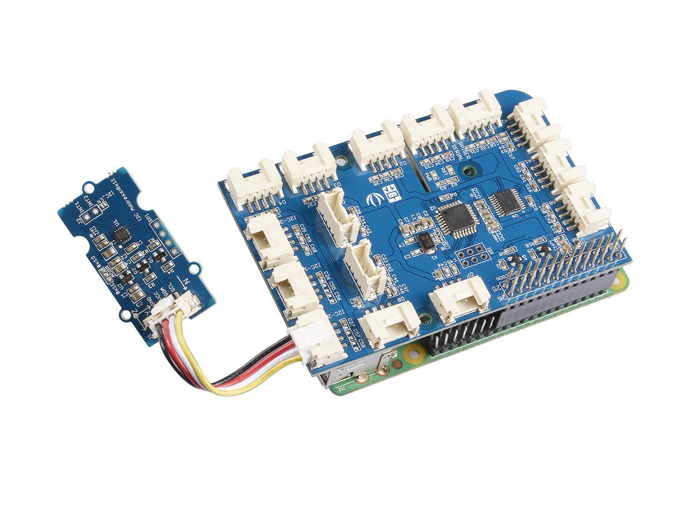
- Paso 2. Conecta el GrovePi_Plus al Raspberry.
- Paso 3. Conecta el Grove-6-Axis_AccelerometerAndCompass_V2.0 al puerto I2C del GrovePi_Plus.
- Paso 4. Conecta el Raspberry a la PC a través del cable USB.
Software
- Paso 1. Sigue Setting Software para configurar el entorno de desarrollo.
- Paso 2. Clona el repositorio de Github con Git.
cd ~
git clone https://github.com/DexterInd/GrovePi.git
- Paso 3. Ejecuta los siguientes comandos para usar este sensor
cd ~/GrovePi/Software/Python/grove_6axis_acc_compass
python grove_6axis_accel_compass_example.py
Aquí está el código del ejemplo:
#!/usr/bin/env python
#
# GrovePi example for using the Grove - 6-Axis Accelerometer&Compass v2.0(https://www.seeedstudio.com/depot/Grove-6Axis-AccelerometerCompass-v20-p-2476.html)
#
# The GrovePi connects the Raspberry Pi and Grove sensors.  You can learn more about GrovePi here:  http://www.dexterindustries.com/GrovePi
#
# Have a question about this library?  Ask on the forums here:  http://forum.dexterindustries.com/c/grovepi
#
'''
## License
The MIT License (MIT)
GrovePi for the Raspberry Pi: an open source platform for connecting Grove Sensors to the Raspberry Pi.
Copyright (C) 2017  Dexter Industries
Permission is hereby granted, free of charge, to any person obtaining a copy
of this software and associated documentation files (the "Software"), to deal
in the Software without restriction, including without limitation the rights
to use, copy, modify, merge, publish, distribute, sublicense, and/or sell
copies of the Software, and to permit persons to whom the Software is
furnished to do so, subject to the following conditions:
The above copyright notice and this permission notice shall be included in
all copies or substantial portions of the Software.
THE SOFTWARE IS PROVIDED "AS IS", WITHOUT WARRANTY OF ANY KIND, EXPRESS OR
IMPLIED, INCLUDING BUT NOT LIMITED TO THE WARRANTIES OF MERCHANTABILITY,
FITNESS FOR A PARTICULAR PURPOSE AND NONINFRINGEMENT. IN NO EVENT SHALL THE
AUTHORS OR COPYRIGHT HOLDERS BE LIABLE FOR ANY CLAIM, DAMAGES OR OTHER
LIABILITY, WHETHER IN AN ACTION OF CONTRACT, TORT OR OTHERWISE, ARISING FROM,
OUT OF OR IN CONNECTION WITH THE SOFTWARE OR THE USE OR OTHER DEALINGS IN
THE SOFTWARE.
'''
import lsm303d

try:
 acc_mag=lsm303d.lsm303d()

 while True:

  # Get accelerometer values
  acc=acc_mag.getRealAccel()

  # Wait for compass to get ready
  while True:
   if acc_mag.isMagReady():
    break

  # Read the heading
  heading= acc_mag.getHeading()

  print("Acceleration of X,Y,Z is %.3fg, %.3fg, %.3fg" %(acc[0],acc[1],acc[2]))
  print("Heading %.3f degrees\n" %(heading))

except IOError:
 print("Unable to read from accelerometer, check the sensor and try again")

Referencias
Haz clic aquí para conocer más sobre este parámetro.


Notas
1. Todos los acelerómetros MEMS de ST están calibrados de fábrica, permitiendo al usuario evitar cualquier calibración adicional para la mayoría de las aplicaciones. Sin embargo, para alcanzar una precisión de rumbo por debajo de 2°, se necesita un procedimiento de calibración sencillo.
2. Al probar el ángulo en sentido horario entre el norte magnético y el eje x, puedes alinear el eje Xa del dispositivo en cualquier dirección, pero no lo hagas mirando hacia abajo. Consulta la imagen a continuación:

Recursos
-
[Librería] Librería del Acelerómetro y Brújula de 6 Ejes v2.0 para arduino
-
[Librería] Librería del Acelerómetro y Brújula de 6 Ejes v2.0 para raspberry pi
-
[Hoja de datos] LSM303D_datashet
-
[Eagle] Archivo eagle del Acelerómetro y Brújula de 6 Ejes v2.0
Soporte Técnico y Discusión de Productos
¡Gracias por elegir nuestros productos! Estamos aquí para brindarte diferentes tipos de soporte para asegurar que tu experiencia con nuestros productos sea lo más fluida posible. Ofrecemos varios canales de comunicación para satisfacer diferentes preferencias y necesidades.