Grove - Micrófono Analógico

El Grove - Micrófono Analógico está basado en la tecnología SiSonic MEMS de alto rendimiento, ofreciendo un micrófono extremadamente silencioso, de bajo consumo, confiable y pequeño para la industria de hardware de código abierto, y tiene un rendimiento mejorado bajo condiciones severas.
Grove - Micrófono Analógico es una opción ideal de sensores de sonido donde se requiere un excelente rendimiento de audio. Puede proporcionar hasta 20dB de ganancia y también cuenta con bajo consumo de corriente, máxima protección RF, lo que lo convierte en un micrófono perfecto para Arduino y Raspberry Pi. Nuestro producto destacado ReSpeaker Core v2.0 también adopta tecnología MEMS y el mismo micrófono que usa Grove - Micrófono Analógico. Si vas a obtener un micrófono elegante, aquí está la opción.
Características
- Tecnología SiSonic MEMS de alto rendimiento
- Extremadamente silencioso, bajo consumo y confiable
- Diseño compacto y elegante
Este sensor de sonido se usa para detectar si hay sonido alrededor o no, por favor no uses el módulo para recopilar señales de sonido. Por ejemplo, puedes usarlo para hacer una lámpara controlada por sonido, pero no como un dispositivo de grabación.
Aplicaciones
- Sensor de sonido
- Recopilación de señales de sonido
- Reconocimiento de voz
- Grabación
Especificaciones
| Elemento | Valor |
|---|---|
| Dimensiones | 20mm x 20mm |
| Voltaje de Operación | 3.3V |
| Corriente de Operación | 5mA |
| Rango de Temperatura de Operación | -40 °C a 100 °C |
Más detalles sobre los módulos Grove consulte Sistema Grove
Plataformas Compatibles
| Arduino | Raspberry Pi | |||
|---|---|---|---|---|
 |  |  |  |  |
Las plataformas mencionadas anteriormente como compatibles son una indicación de la compatibilidad de software o teórica del módulo. Solo proporcionamos biblioteca de software o ejemplos de código para la plataforma Arduino en la mayoría de los casos. No es posible proporcionar biblioteca de software / código de demostración para todas las plataformas MCU posibles. Por lo tanto, los usuarios tienen que escribir su propia biblioteca de software.
Primeros Pasos
Si esta es la primera vez que trabajas con Arduino, te recomendamos firmemente que veas Primeros Pasos con Arduino antes de comenzar.
Jugar con Arduino
Hardware
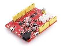
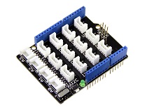
| Seeeduino V4.2 | Base Shield | Grove-Analog Microphone |
|---|---|---|
 |  |  |
| Obtener Uno Ahora | Obtener Uno Ahora | Obtener Uno Ahora |
- Paso 1. Conecta el Sensor de Sonido Grove al puerto A0 del Escudo Base Grove.
- Paso 2. Conecta el Escudo Base Grove al Seeeduino y conecta el Seeeduino a la PC mediante un cable USB.

Si no tenemos el Escudo Base Grove, también podemos conectar directamente el Sensor de Sonido Grove al Seeeduino como se muestra a continuación.
| Seeeduino | Sensor de Sonido Grove |
|---|---|
| 5V | Rojo |
| GND | Negro |
| A1 | Blanco |
| A0 | Amarillo |
Software
- Paso 1. Por favor copia el código de abajo al IDE de Arduino y súbelo al arduino. Si no sabes cómo subir el código, por favor revisa cómo subir código.
/*
  Analog input, analog output, serial output

  Reads an analog input pin, maps the result to a range from 0 to 255 and uses
  the result to set the pulse width modulation (PWM) of an output pin.
  Also prints the results to the Serial Monitor.
*/

// These constants won't change. They're used to give names to the pins used:
const int analogInPin = A0;  // Analog input pin that the potentiometer is attached to
const int analogOutPin = 9; // Analog output pin that the LED is attached to

int sensorValue = 0;        // value read from the pot
int outputValue = 0;        // value output to the PWM (analog out)

void setup() {
  Serial.begin(9600);      // initialize serial communications at 9600 bps
}

void loop() {
  sensorValue = analogRead(analogInPin);        // read the analog in value
  outputValue = map(sensorValue, 0, 1023, 0, 255);       // map it to the range of the analog out
  analogWrite(analogOutPin, outputValue);               // change the analog out value

  Serial.println(outputValue);    // print the results to the Serial Monitor

  // wait 2 milliseconds before the next loop for the analog-to-digital
  // converter to settle after the last reading:
  delay(2);
}
- Paso 2. Haz clic en Serial > Plotter para obtener la curva cambiante del sensor. Por favor haz ruido para ver el cambio del valor.

Jugar con Wio Terminal
Hardware
| Wio Terminal | Grove-Analog Microphone |
|---|---|
 |  |
| Obtener Uno Ahora | Obtener Uno Ahora |
Conexión de Hardware

Paso 1 Conecta Grove-Analog Microphone a Wio Terminal a través del cable Grove y también conecta Wio Terminal a la PC a través de un cable USB.
Paso 2 Copia el código de demostración en tu Arduino IDE y súbelo.
Software
#include "seeed_line_chart.h" //include the library

TFT_eSPI tft;
#define LINE_DIS 0X00
#define STRING_DIS 0X01
#define max_size 30 //maximum size of data
doubles data;       //Initilising a doubles type to store data
int brightness;
TFT_eSprite spr = TFT_eSprite(&tft); // Sprite

const int MIC = A0; //the microphone amplifier output is connected to pin A0
int adc;
int dB, PdB; //the variable that will hold the value read from the microphone each time
uint8_t mode = LINE_DIS;
void setup()
{
    Serial.begin(9600); //sets the baud rate at 9600 so we can check the values the microphone is obtaining on the Serial Monitor
    pinMode(A0, INPUT);
    pinMode(WIO_KEY_C, INPUT_PULLUP);
    pinMode(WIO_BUZZER, OUTPUT);
    tft.begin();
    spr.createSprite(TFT_HEIGHT, TFT_WIDTH);
    spr.setRotation(3);
    tft.setRotation(3);
}

void loop() {

    if (digitalRead(WIO_KEY_C) == LOW) {
        mode ++;
        if(mode > STRING_DIS ) mode = LINE_DIS;
        while(!digitalRead(WIO_KEY_C));
    }
    display(mode);
}

void display(uint8_t mode)
{
    adc = analogRead(MIC); //Read the ADC value from amplifer
    //Serial.println (adc);//Print ADC for initial calculation
    dB = (adc + 83.2073) / 7.003; //Convert ADC value to dB using Regression values

    if(dB > 50)
    {
        analogWrite(WIO_BUZZER, 128);

    }else{
        analogWrite(WIO_BUZZER, 0);
    }

    spr.fillSprite(TFT_WHITE);

    if (data.size() == max_size)
    {
        data.pop(); //this is used to remove the first read variable
    }
    data.push(dB); //read variables and store in data

    //Settings for the line graph title
    auto header = text(0, 0)
                      .value("MIC DB Readings")
                      .align(center)
                      .valign(vcenter)
                      .width(tft.width())
                      .thickness(2);

    header.height(header.font_height() * 2);
    header.draw(); //Header height is the twice the height of the font
    if (LINE_DIS == mode){
    //Settings for the line graph
    auto content = line_chart(20, header.height()); //(x,y) where the line graph begins
    content
        .height(tft.height() - header.height() * 1.5) //actual height of the line chart
        .width(tft.width() - content.x() * 2)         //actual width of the line chart
        .based_on(0.0)                                //Starting point of y-axis, must be a float
        .show_circle(false)                           //drawing a cirle at each point, default is on.
        .value(data)                                  //passing through the data to line graph
        .color(TFT_RED)                               //Setting the color for the line
        .draw();
    } else if (STRING_DIS == mode){
        for(int8_t line_index = 0;line_index < 5 ; line_index++)
        {
            spr.drawLine(0, 50 + line_index, tft.width(), 50 + line_index, TFT_GREEN);
        }
        auto header =  text(0, 0)
                    .thickness(1);
        spr.setFreeFont(&FreeSansBoldOblique24pt7b);
        if(dB > 50){
            spr.setTextColor(TFT_RED);
        }else{
            spr.setTextColor(TFT_BLUE);
        }
        spr.drawFloat(dB,2,70,110);
        spr.drawString(" dB",80 + 100,110,1);
    }
    spr.pushSprite(0, 0);
    delay(100);
}
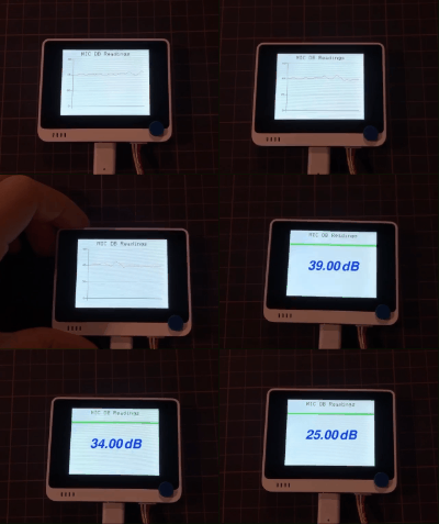
La imagen se mostrará en la pantalla del Wio Terminal si todo va bien.

Visor de Esquemático en Línea
Recursos
Soporte Técnico y Discusión de Productos
¡Gracias por elegir nuestros productos! Estamos aquí para brindarle diferentes tipos de soporte para asegurar que su experiencia con nuestros productos sea lo más fluida posible. Ofrecemos varios canales de comunicación para satisfacer diferentes preferencias y necesidades.