Grove - Sensor de Electricidad
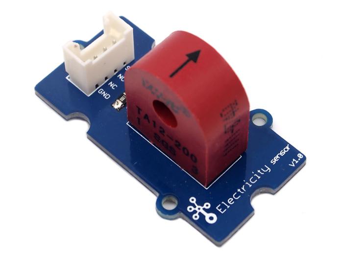
El módulo sensor de electricidad es un miembro de Grove. Está basado en el transformador de corriente TA12-200 que puede transformar la gran CA en pequeña amplitud. Puedes usarlo para probar corriente alterna grande hasta 5A.

Características
- Interfaz compatible con Grove
- Entrada máxima de 5A
- Alta precisión
- Tamaño pequeño
Para más detalles sobre los módulos Grove, consulte Sistema Grove
Ideas de Aplicación
- Medición de corriente alterna
- Monitoreo de condición de dispositivos
Especificación
Especificación Clave
| Elementos | Min |
|---|---|
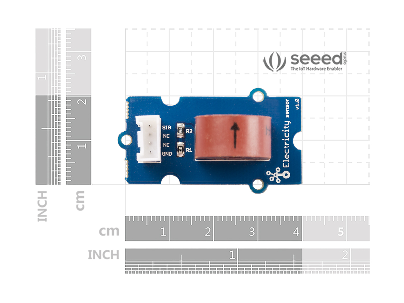
| Tamaño PCB | 2.0cm*4.0cm |
| Interfaz | Conector de pin de 2.0mm de paso |
| Estructura IO | SIG,NC,NC,GND |
| RoHS | SÍ |
Características Electrónicas
| Elementos | Mín | Nom | Máx | Unidad |
|---|---|---|---|---|
| Relación de transformación | - | 2000:1 | - | - |
| Corriente de Entrada | 0 | - | 5 | A |
| Corriente de Salida | 0 | - | 2.5 | mA |
| Resistencia de Muestreo | - | 800 | - | Ω |
| Voltaje de Muestreo | 0 | - | 2 | V |
| Frecuencia de Trabajo | 20 | - | 20K | HZ |
| Escala no lineal | - | - | 0.2% | - |
| Desplazamiento de Fase | - | - | 5' | - |
| Temperatura de Operación | -55 | - | 85 | ℃ |
| Resistencia dieléctrica | - | 6 | - | KVAC/1min |
Descripción General del Hardware
Plataformas Compatibles
| Arduino | Raspberry Pi | |||
|---|---|---|---|---|
Las plataformas mencionadas anteriormente como compatibles son una indicación de la compatibilidad de software o teórica del módulo. Solo proporcionamos biblioteca de software o ejemplos de código para la plataforma Arduino en la mayoría de los casos. No es posible proporcionar biblioteca de software / código de demostración para todas las plataformas MCU posibles. Por lo tanto, los usuarios tienen que escribir su propia biblioteca de software.
Primeros pasos
Jugar con Arduino
El siguiente sketch demuestra una aplicación simple de medición de la amplitud del voltaje alterno. El pin SIG emitirá un voltaje alterno basado en la corriente alterna que se está midiendo. Puedes medir el valor usando ADC.
Hardware
- Paso 1. Prepara los siguientes elementos:
| Seeeduino V4.2 | Base Shield | Grove-Electricity_Sensor |
|---|---|---|
 |  |  |
| Obtener Uno Ahora | Obtener Uno Ahora | Obtener Uno Ahora |
- Paso 2. Conecta el Grove-Electricity_Sensor al puerto A0 del Grove-Base Shield.
- Paso 3. Conecta el Grove - Base Shield al Seeeduino.
- Paso 4. Conecta el Seeeduino a la PC mediante un cable USB.

Si no tenemos el Grove Base Shield, también podemos conectar directamente este módulo al Seeeduino como se muestra a continuación.
| Seeeduino | Grove-Electricity_Sensor |
|---|---|
| 5V | Rojo |
| GND | Negro |
| No Conectado | Blanco |
| A0 | Amarillo |
Software
Paso 1. Copia el código y grábalo en la placa controladora y sube el código.
    /****************************************************************************/
    //  Function: Measure the amplitude current of the alternating current and
    //            the effective current of the sinusoidal alternating current.
    //  Hardware: Grove - Electricity Sensor
    //  Date:    Jan 19,2013
    //  by www.seeedstudio.com
    #define ELECTRICITY_SENSOR A0 // Analog input pin that sensor is attached to

    float amplitude_current;               //amplitude current
    float effective_value;       //effective current

    void setup()
    {
        Serial.begin(9600);
        pins_init();
    }
    void loop()
    {
        int sensor_max;
        sensor_max = getMaxValue();
        Serial.print("sensor_max = ");
        Serial.println(sensor_max);
        //the VCC on the Grove interface of the sensor is 5v
        amplitude_current=(float)sensor_max/1024*5/800*2000000;
        effective_value=amplitude_current/1.414;//minimum_current=1/1024*5/800*2000000/1.414=8.6(mA)
                            //Only for sinusoidal alternating current
        Serial.println("The amplitude of the current is(in mA)");
        Serial.println(amplitude_current,1);//Only one number after the decimal point
        Serial.println("The effective value of the current is(in mA)");
        Serial.println(effective_value,1);
    }
    void pins_init()
    {
        pinMode(ELECTRICITY_SENSOR, INPUT);
    }
    /*Function: Sample for 1000ms and get the maximum value from the SIG pin*/
    int getMaxValue()
    {
        int sensorValue;             //value read from the sensor
        int sensorMax = 0;
        uint32_t start_time = millis();
        while((millis()-start_time) < 1000)//sample for 1000ms
        {
            sensorValue = analogRead(ELECTRICITY_SENSOR);
            if (sensorValue > sensorMax)
            {
                /*record the maximum sensor value*/
                sensorMax = sensorValue;
            }
        }
        return sensorMax;
    }
La corriente efectiva mínima que puede ser detectada por el código se puede calcular usando la ecuación siguiente. corriente_mínima=1/10245/8002000000/1.414=8.6(mA).
- Paso 2. Abre el monitor serie, Los resultados son los siguientes:

Con Raspberry Pi
Hardware
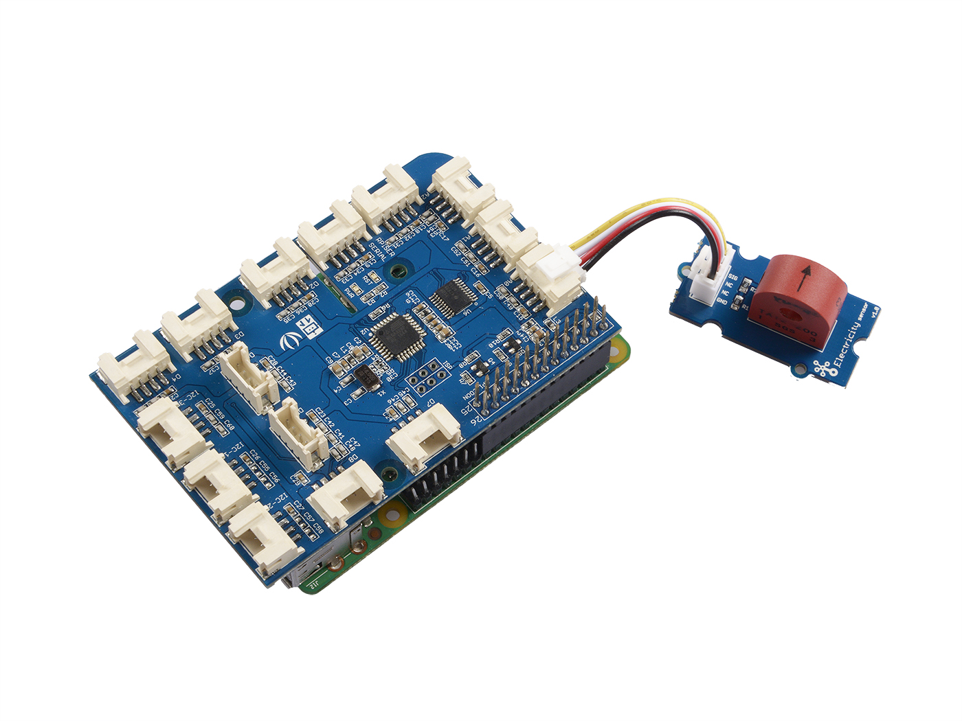
- Paso 1. Prepara los siguientes elementos:
| Raspberry pi | GrovePi_Plus | Grove-Electricity_Sensor |
|---|---|---|
 |  | |
| Consigue Uno Ahora | Consigue Uno Ahora | Consigue Uno Ahora |
- Paso 2. Conecta el GrovePi_Plus al Raspberry.
- Paso 3. Conecta el Grove-Electricity_Sensor al puerto A0 del GrovePi_Plus.
- Paso 4. Conecta el Raspberry a la PC a través del cable USB.
Software
- Paso 1. Sigue Setting Software para configurar el entorno de desarrollo.
- Paso 2. Clona el repositorio de Github con Git.
cd ~
git clone https://github.com/DexterInd/GrovePi.git
- Paso 3. Ejecuta los siguientes comandos para usar este sensor
cd ~/GrovePi/Software/Python
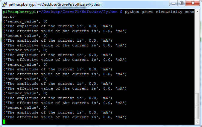
python grove_electricity_sensor.py
Aquí está el código del ejemplo:
#!/usr/bin/env python
#
# GrovePi Example for using the Grove Electricity Sensor (https://www.seeedstudio.com/wiki/Grove_-_Electricity_Sensor)
#
# The GrovePi connects the Raspberry Pi and Grove sensors.  You can learn more about GrovePi here:  http://www.dexterindustries.com/GrovePi
#
# Have a question about this example?  Ask on the forums here:  http://forum.dexterindustries.com/c/grovepi
#
'''
## License
The MIT License (MIT)
GrovePi for the Raspberry Pi: an open source platform for connecting Grove Sensors to the Raspberry Pi.
Copyright (C) 2017  Dexter Industries
Permission is hereby granted, free of charge, to any person obtaining a copy
of this software and associated documentation files (the "Software"), to deal
in the Software without restriction, including without limitation the rights
to use, copy, modify, merge, publish, distribute, sublicense, and/or sell
copies of the Software, and to permit persons to whom the Software is
furnished to do so, subject to the following conditions:
The above copyright notice and this permission notice shall be included in
all copies or substantial portions of the Software.
THE SOFTWARE IS PROVIDED "AS IS", WITHOUT WARRANTY OF ANY KIND, EXPRESS OR
IMPLIED, INCLUDING BUT NOT LIMITED TO THE WARRANTIES OF MERCHANTABILITY,
FITNESS FOR A PARTICULAR PURPOSE AND NONINFRINGEMENT. IN NO EVENT SHALL THE
AUTHORS OR COPYRIGHT HOLDERS BE LIABLE FOR ANY CLAIM, DAMAGES OR OTHER
LIABILITY, WHETHER IN AN ACTION OF CONTRACT, TORT OR OTHERWISE, ARISING FROM,
OUT OF OR IN CONNECTION WITH THE SOFTWARE OR THE USE OR OTHER DEALINGS IN
THE SOFTWARE.
'''

import time
import grovepi

# Connect the Grove Electricity Sensor to analog port A0
# SIG,NC,NC,GND
sensor = 0

grovepi.pinMode(sensor,"INPUT")

# Vcc of the grove interface is normally 5v
grove_vcc = 5

while True:
  try:
      # Get sensor value
      sensor_value = grovepi.analogRead(sensor)

      # Calculate amplitude current (mA)
      amplitude_current = (float)(sensor_value / 1024 * grove_vcc / 800 * 2000000)

      # Calculate effective value (mA)
      effective_value = amplitude_current / 1.414

      # minimum_current = 1 / 1024 * grove_vcc / 800 * 2000000 / 1.414 = 8.6(mA)
      # Only for sinusoidal alternating current

      print("sensor_value", sensor_value)
      print("The amplitude of the current is", amplitude_current, "mA")
      print("The effective value of the current is", effective_value, "mA")
      time.sleep(1)

  except IOError:
      print ("Error")
Visor de Esquemas en Línea
Recursos
- [Eagle] Archivo Eagle del Sensor de Electricidad Grove
- [PDF] Esquema en PDF
Soporte Técnico y Discusión de Productos
¡Gracias por elegir nuestros productos! Estamos aquí para brindarle diferentes tipos de soporte para asegurar que su experiencia con nuestros productos sea lo más fluida posible. Ofrecemos varios canales de comunicación para satisfacer diferentes preferencias y necesidades.