Grove - Cámara de Imagen Térmica IR-Array MLX90641
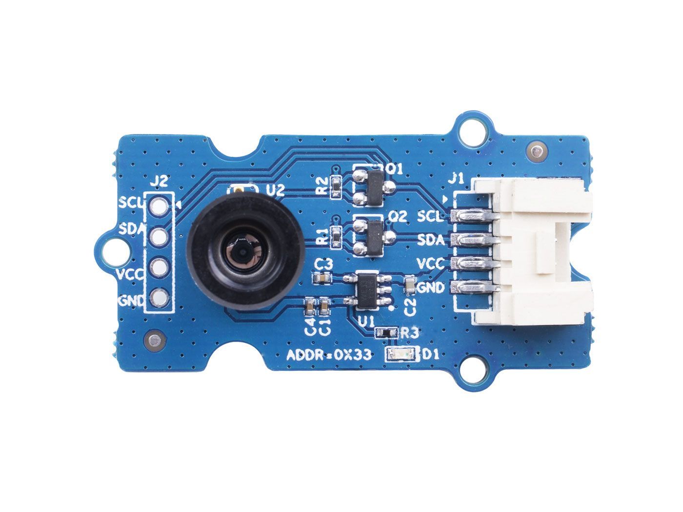
Esta cámara térmica IR lleva un arreglo de 16x12 sensores térmicos (MLX90641) y puede detectar la temperatura de objetos desde lejos con una precisión del área central de ±1℃ y una precisión promedio de ±1.5℃. Para obtener las imágenes térmicas fácilmente, se utiliza el protocolo I2C para obtener las imágenes de baja resolución de la cámara. El FOV (Campo de Visión) de esta cámara es de 110°x75°, y el rango de medición de temperatura es de -40℃ a 300℃. Para obtener la imagen térmica fácilmente, se utiliza el protocolo I2C para obtener la imagen de baja resolución de la cámara.
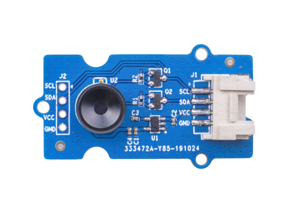
Mientras que Grove - Cámara de Imagen Térmica es un sensor térmico (MLX90640), que lleva un arreglo de 32x24 sensores térmicos, y puede detectar la temperatura de objetos desde pies de distancia con la precisión de ±1.5℃ y puede presentar imágenes térmicas dinámicas y detectar la temperatura circundante desde -40℃~300℃. La cámara con ángulo estrecho/ángulo amplio tiene un FOV(Campo de Visión) de 55°x35°/110°x75°. Para obtener la imagen térmica fácilmente, se utiliza el protocolo I2C para obtener la imagen de baja resolución de la cámara.
Versiones
| Versión | Fecha de Lanzamiento | Pedido |
|---|---|---|
| Grove - Cámara de Imagen Térmica / IR Array MLX90641 110 grados [Nuevo] | 03-Junio-2020 | Cómpralo |
| Grove - Cámara de Imagen Térmica / IR Array MLX90640 110 grados | 12-Nov-2019 | Cómpralo |
Esta wiki es compatible con ambos tipos de la Cámara de Imagen Térmica IR Array MLX90641 y MLX90640.
Características
- Tamaño compacto de matriz de sensor térmico IR de 16x12 píxeles (MLX90641), matriz de sensor térmico IR de 32x24 píxeles (MLX90640)
- Alto FOV (campo de visión) de 110°x75° para capturar más área
- Amplio rango de medición de temperatura (-40℃~300℃)
- Interfaz I2C Grove para comunicación fácil con un MCU
- Matriz IR completamente calibrada para configuración conveniente
Especificación
| Elemento | Grove - Cámara de Imagen Térmica - MLX90640 | Grove - Cámara de Imagen Térmica - MLX90641 |
|---|---|---|
| Sensor térmico | matriz 32X24 MLX90640 | matriz 16x12 MLX90641 |
|Voltaje de Operación|3.3V - 5V|3.3V - 5V |Consumo de Corriente|~18mA|~18mA| |FOV(Campo de Visión)|110°x75°|110°x75°| |Rango de Medición de Temperatura|-40°C - 300°C|-40°C - 300°C |Resolución de Temperatura|± 1.5°C|± 1.5°C (±1℃ en el área central)| |Frecuencia de Actualización|0.5Hz - 64Hz|0.5Hz - 64Hz| |Interfaz|Interfaz I2C Grove|Interfaz I2C Grove| |Dirección I2C|0x33|0x33|
Plataformas Soportadas
| Arduino | Raspberry Pi | |||
|---|---|---|---|---|
Comenzando
Comenzando con Wio Terminal
Materiales requeridos
| Wio Terminal | Grove - Cámara de Imagen Térmica / Matriz IR MLX90641 110 grados |
|---|---|
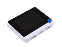 |  |
| Consigue uno ahora | Consigue uno ahora |
Conexión de Hardware
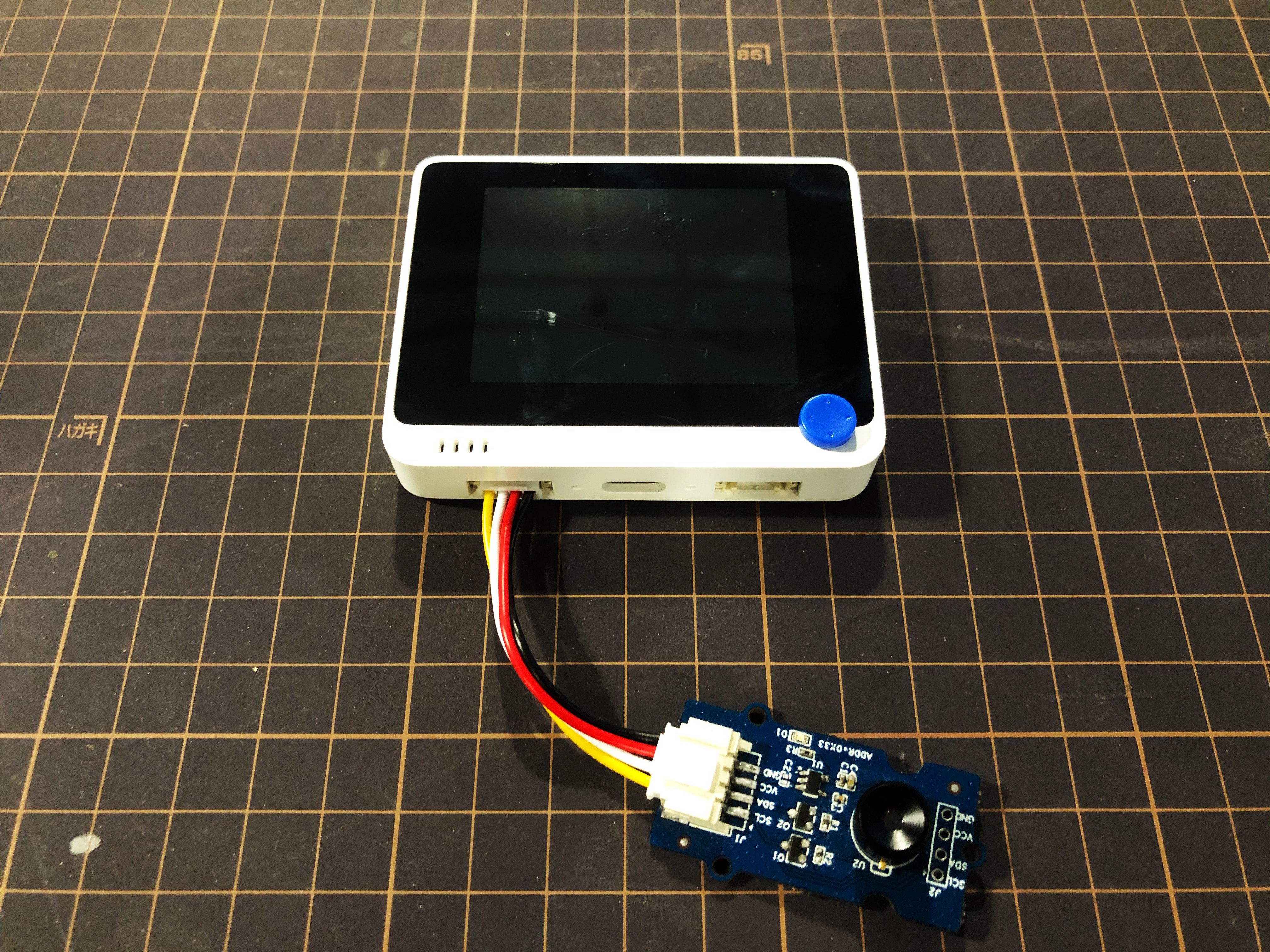
Paso 1. Conecta Grove - Thermal Imaging Camera al Wio Terminal mediante el cable Grove y también conecta el Wio Terminal a la PC a través de un cable USB.
Paso 2. Descarga la Librería y copia todo el archivo Seeed_Arduino_MLX9064x y pégalo en tu archivo de librerías del Arduino IDE.
Si es la primera vez que juegas con Wio Terminal y no estás seguro de qué interfaz conectar en el Wio Terminal, por favor consulta Comenzar con Wio Terminal.
Paso 3. Copia el Código de Software 1 a continuación en tu Arduino IDE y súbelo para el formato de visualización mostrado a través del Puerto Serie.
Resultado del Formato de Visualización
Código de Software 1
/*
    Output the temperature readings to all pixels to be read by a Processing visualizer
*/

#include <Wire.h>

#define USE_MLX90641

#ifndef USE_MLX90641
    #include "MLX90640_API.h"
#else
    #include "MLX90641_API.h"
#endif

#include "MLX9064X_I2C_Driver.h"

#if defined(ARDUINO_ARCH_AVR)
    #define debug  Serial

#elif defined(ARDUINO_ARCH_SAMD) ||  defined(ARDUINO_ARCH_SAM)
    #define debug  Serial
#else
    #define debug  Serial
#endif

#ifdef USE_MLX90641
    const byte MLX90641_address = 0x33; //Default 7-bit unshifted address of the MLX90641
    #define TA_SHIFT 8 //Default shift for MLX90641 in open air

    uint16_t eeMLX90641[832];
    float MLX90641To[192];
    uint16_t MLX90641Frame[242];
    paramsMLX90641 MLX90641;
    int errorno = 0;
#else
    const byte MLX90640_address = 0x33; //Default 7-bit unshifted address of the MLX90640

    #define TA_SHIFT 8 //Default shift for MLX90640 in open air

    float mlx90640To[768];
    paramsMLX90640 mlx90640;
#endif
void setup() {
    Wire.begin();
    Wire.setClock(400000); //Increase I2C clock speed to 400kHz

    debug.begin(115200); //Fast debug as possible

    while (!debug); //Wait for user to open terminal
    //debug.println("MLX90640 IR Array Example");


#ifndef USE_MLX90641
    if (isConnected() == false) {
        debug.println("MLX9064x not detected at default I2C address. Please check wiring. Freezing.");
        while (1);
    }
    //Get device parameters - We only have to do this once
    int status;
    uint16_t eeMLX90640[832];
    status = MLX90640_DumpEE(MLX90640_address, eeMLX90640);
    if (status != 0) {
        debug.println("Failed to load system parameters");
    }

    status = MLX90640_ExtractParameters(eeMLX90640, &mlx90640);
    if (status != 0) {
        debug.println("Parameter extraction failed");
    }

    //Once params are extracted, we can release eeMLX90640 array

    //MLX90640_SetRefreshRate(MLX90640_address, 0x02); //Set rate to 2Hz
    MLX90640_SetRefreshRate(MLX90640_address, 0x03); //Set rate to 4Hz
    //MLX90640_SetRefreshRate(MLX90640_address, 0x07); //Set rate to 64H
#else
    if (isConnected() == false) {
        debug.println("MLX90641 not detected at default I2C address. Please check wiring. Freezing.");
        while (1);
    }
    //Get device parameters - We only have to do this once
    int status;
    status = MLX90641_DumpEE(MLX90641_address, eeMLX90641);
    errorno = status;//MLX90641_CheckEEPROMValid(eeMLX90641);//eeMLX90641[10] & 0x0040;//

    if (status != 0) {
        debug.println("Failed to load system parameters");
       while(1);
    }

    status = MLX90641_ExtractParameters(eeMLX90641, &MLX90641);
    //errorno = status;
    if (status != 0) {
        debug.println("Parameter extraction failed");
        while(1);
    }

    //Once params are extracted, we can release eeMLX90641 array

    //MLX90641_SetRefreshRate(MLX90641_address, 0x02); //Set rate to 2Hz
    MLX90641_SetRefreshRate(MLX90641_address, 0x03); //Set rate to 4Hz
    //MLX90641_SetRefreshRate(MLX90641_address, 0x07); //Set rate to 64Hz
#endif

}

void loop() {
#ifndef USE_MLX90641
    long startTime = millis();
    for (byte x = 0 ; x < 2 ; x++) {
        uint16_t mlx90640Frame[834];
        int status = MLX90640_GetFrameData(MLX90640_address, mlx90640Frame);

        float vdd = MLX90640_GetVdd(mlx90640Frame, &mlx90640);
        float Ta = MLX90640_GetTa(mlx90640Frame, &mlx90640);

        float tr = Ta - TA_SHIFT; //Reflected temperature based on the sensor ambient temperature
        float emissivity = 0.95;

        MLX90640_CalculateTo(mlx90640Frame, &mlx90640, emissivity, tr, mlx90640To);
    }
    long stopTime = millis();

    for (int x = 0 ; x < 768 ; x++) {
        //if(x % 8 == 0) debug.println();
        debug.print(mlx90640To[x], 2);
        debug.print(",");
    }
    debug.println("");
#else
    long startTime = millis();

    for (byte x = 0 ; x < 2 ; x++) {
        int status = MLX90641_GetFrameData(MLX90641_address, MLX90641Frame);

        float vdd = MLX90641_GetVdd(MLX90641Frame, &MLX90641);
        float Ta = MLX90641_GetTa(MLX90641Frame, &MLX90641);

        float tr = Ta - TA_SHIFT; //Reflected temperature based on the sensor ambient temperature
        float emissivity = 0.95;

        MLX90641_CalculateTo(MLX90641Frame, &MLX90641, emissivity, tr, MLX90641To);
    }
    long stopTime = millis();
   /*
    debug.print("vdd=");
    debug.print(vdd,2);
    debug.print(",Ta=");
    debug.print(Ta,2);

    debug.print(",errorno=");
    debug.print(errorno,DEC);


    for (int x = 0 ; x < 64 ; x++) {
        debug.print(MLX90641Frame[x], HEX);
        debug.print(",");
    }

    delay(1000);
    */
    for (int x = 0 ; x < 192 ; x++) {
        debug.print(MLX90641To[x], 2);
        debug.print(",");
    }
    debug.println("");
#endif
}

//Returns true if the MLX90640 is detected on the I2C bus
boolean isConnected() {
#ifndef USE_MLX90641
    Wire.beginTransmission((uint8_t)MLX90640_address);
#else
    Wire.beginTransmission((uint8_t)MLX90641_address);
#endif
    if (Wire.endTransmission() != 0) {
        return (false);    //Sensor did not ACK
    }
    return (true);
}
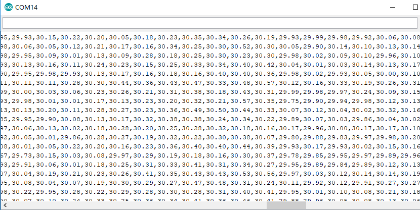
Sube el código de software 1 anterior a tu Arduino IDE y abre el Puerto Serie, verás un resultado en formato de visualización como el siguiente:
Resultado de Visualización en Wio Terminal
Paso 4. Sube el Código de Software 2 a continuación a tu Arduino IDE para la visualización mostrada en Wio Terminal.
Código de Software 2
#include <Wire.h>
#include "MLX90641_API.h"
#include "MLX9064X_I2C_Driver.h"
#include <TFT_eSPI.h>                // Include the graphics library (this includes the sprite functions)

const byte MLX90641_address = 0x33; //Default 7-bit unshifted address of the MLX90641
#define TA_SHIFT 12 //Default shift for MLX90641 in open air
#define debug  Serial
uint16_t eeMLX90641[832];
float MLX90641To[192];
uint16_t MLX90641Frame[242];
paramsMLX90641 MLX90641;
int errorno = 0;

TFT_eSPI    tft = TFT_eSPI();
TFT_eSprite Display = TFT_eSprite(&tft);  // Create Sprite object "img" with pointer to "tft" object
// the pointer is used by pushSprite() to push it onto the TFT

unsigned long CurTime;

uint16_t TheColor;
// start with some initial colors
uint16_t MinTemp = 25;
uint16_t MaxTemp = 38;

// variables for interpolated colors
byte red, green, blue;

// variables for row/column interpolation
byte i, j, k, row, col, incr;
float intPoint, val, a, b, c, d, ii;
byte aLow, aHigh;

// size of a display "pixel"
byte BoxWidth = 3;
byte BoxHeight = 3;

int x, y;
char buf[20];

// variable to toggle the display grid
int ShowGrid = -1;

// array for the interpolated array
float HDTemp[6400];

void setup() {
    Wire.begin();
    Wire.setClock(2000000); //Increase I2C clock speed to 2M
    debug.begin(115200); //Fast debug as possible

    // start the display and set the background to black

    if (isConnected() == false) {
        debug.println("MLX90641 not detected at default I2C address. Please check wiring. Freezing.");
        while (1);
    }
    //Get device parameters - We only have to do this once
    int status;
    status = MLX90641_DumpEE(MLX90641_address, eeMLX90641);
    errorno = status;//MLX90641_CheckEEPROMValid(eeMLX90641);//eeMLX90641[10] & 0x0040;//

    if (status != 0) {
        debug.println("Failed to load system parameters");
       while(1);
    }

    status = MLX90641_ExtractParameters(eeMLX90641, &MLX90641);
    //errorno = status;
    if (status != 0) {
        debug.println("Parameter extraction failed");
        while(1);
    }

    //Once params are extracted, we can release eeMLX90641 array

    MLX90641_SetRefreshRate(MLX90641_address, 0x05); //Set rate to 16Hz

    tft.begin();
    tft.setRotation(3);
    tft.fillScreen(TFT_BLACK);
    Display.createSprite(TFT_HEIGHT, TFT_WIDTH);
    Display.fillSprite(TFT_BLACK);

    // get the cutoff points for the color interpolation routines
    // note this function called when the temp scale is changed
    Getabcd();

    // draw a legend with the scale that matches the sensors max and min
    DrawLegend();
}
void loop() {
    // draw a large white border for the temperature area
    Display.fillRect(10, 10, 220, 220, TFT_WHITE);
    for (byte x = 0 ; x < 2 ; x++) {
        int status = MLX90641_GetFrameData(MLX90641_address, MLX90641Frame);

        float vdd = MLX90641_GetVdd(MLX90641Frame, &MLX90641);
        float Ta = MLX90641_GetTa(MLX90641Frame, &MLX90641);

        float tr = Ta - TA_SHIFT; //Reflected temperature based on the sensor ambient temperature
        float emissivity = 0.95;

        MLX90641_CalculateTo(MLX90641Frame, &MLX90641, emissivity, tr, MLX90641To);
    }

    interpolate_image(MLX90641To,12,16,HDTemp,80,80);

    //display the 80 x 80 array
    DisplayGradient();

    //Crosshair in the middle of the screen
    Display.drawCircle(115, 115, 5, TFT_WHITE);
    Display.drawFastVLine(115, 105, 20, TFT_WHITE);
    Display.drawFastHLine(105, 115, 20, TFT_WHITE);
    //Displaying the temp at the middle of the Screen

    //Push the Sprite to the screen
    Display.pushSprite(0, 0);

    tft.setRotation(3);
    tft.setTextColor(TFT_WHITE);
    tft.drawFloat(HDTemp[35 * 80 + 35], 2, 90, 20);

}
//Returns true if the MLX90640 is detected on the I2C bus
boolean isConnected() {
    Wire.beginTransmission((uint8_t)MLX90641_address);
    if (Wire.endTransmission() != 0) {
        return (false);    //Sensor did not ACK
    }
    return (true);
}
// function to display the results
void DisplayGradient() {

  tft.setRotation(4);

  // rip through 70 rows
  for (row = 0; row < 70; row ++) {

    // fast way to draw a non-flicker grid--just make every 10 MLX90641To 2x2 as opposed to 3x3
    // drawing lines after the grid will just flicker too much
    if (ShowGrid < 0) {
      BoxWidth = 3;
    }
    else {
      if ((row % 10 == 9) ) {
        BoxWidth = 2;
      }
      else {
        BoxWidth = 3;
      }
    }
    // then rip through each 70 cols
    for (col = 0; col < 70; col++) {

      // fast way to draw a non-flicker grid--just make every 10 MLX90641To 2x2 as opposed to 3x3
      if (ShowGrid < 0) {
        BoxHeight = 3;
      }
      else {
        if ( (col % 10 == 9)) {
          BoxHeight = 2;
        }
        else {
          BoxHeight = 3;
        }
      }
      // finally we can draw each the 70 x 70 points, note the call to get interpolated color
      Display.fillRect((row * 3) + 15, (col * 3) + 15, BoxWidth, BoxHeight, GetColor(HDTemp[row * 80 + col]));
    }
  }

}
// my fast yet effective color interpolation routine
uint16_t GetColor(float val) {

  /*
    pass in value and figure out R G B
    several published ways to do this I basically graphed R G B and developed simple linear equations
    again a 5-6-5 color display will not need accurate temp to R G B color calculation

    equations based on
    http://web-tech.ga-usa.com/2012/05/creating-a-custom-hot-to-cold-temperature-color-gradient-for-use-with-rrdtool/index.html

  */

  red = constrain(255.0 / (c - b) * val - ((b * 255.0) / (c - b)), 0, 255);

  if ((val > MinTemp) & (val < a)) {
    green = constrain(255.0 / (a - MinTemp) * val - (255.0 * MinTemp) / (a - MinTemp), 0, 255);
  }
  else if ((val >= a) & (val <= c)) {
    green = 255;
  }
  else if (val > c) {
    green = constrain(255.0 / (c - d) * val - (d * 255.0) / (c - d), 0, 255);
  }
  else if ((val > d) | (val < a)) {
    green = 0;
  }

  if (val <= b) {
    blue = constrain(255.0 / (a - b) * val - (255.0 * b) / (a - b), 0, 255);
  }
  else if ((val > b) & (val <= d)) {
    blue = 0;
  }
  else if (val > d) {
    blue = constrain(240.0 / (MaxTemp - d) * val - (d * 240.0) / (MaxTemp - d), 0, 240);
  }

  // use the displays color mapping function to get 5-6-5 color palet (R=5 bits, G=6 bits, B-5 bits)
  return Display.color565(red, green, blue);

}

// function to get the cutoff points in the temp vs RGB graph
void Getabcd() {

  a = MinTemp + (MaxTemp - MinTemp) * 0.2121;
  b = MinTemp + (MaxTemp - MinTemp) * 0.3182;
  c = MinTemp + (MaxTemp - MinTemp) * 0.4242;
  d = MinTemp + (MaxTemp - MinTemp) * 0.8182;

}
float get_point(float *p, uint8_t rows, uint8_t cols, int8_t x, int8_t y)
{
    if (x < 0)
    {
        x = 0;
    }
    if (y < 0)
    {
        y = 0;
    }
    if (x >= cols)
    {
        x = cols - 1;
    }
    if (y >= rows)
    {
        y = rows - 1;
    }
    return p[y * cols + x];
}

void set_point(float *p, uint8_t rows, uint8_t cols, int8_t x, int8_t y, float f)
{
    if ((x < 0) || (x >= cols))
    {
        return;
    }
    if ((y < 0) || (y >= rows))
    {
        return;
    }
    p[y * cols + x] = f;
}

// src is a grid src_rows * src_cols
// dest is a pre-allocated grid, dest_rows*dest_cols
void interpolate_image(float *src, uint8_t src_rows, uint8_t src_cols,
                       float *dest, uint8_t dest_rows, uint8_t dest_cols)
{
    float mu_x = (src_cols - 1.0) / (dest_cols - 1.0);
    float mu_y = (src_rows - 1.0) / (dest_rows - 1.0);

    float adj_2d[16]; // matrix for storing adjacents

    for (uint8_t y_idx = 0; y_idx < dest_rows; y_idx++)
    {
        for (uint8_t x_idx = 0; x_idx < dest_cols; x_idx++)
        {
            float x = x_idx * mu_x;
            float y = y_idx * mu_y;
            get_adjacents_2d(src, adj_2d, src_rows, src_cols, x, y);

            float frac_x = x - (int)x; // we only need the ~delta~ between the points
            float frac_y = y - (int)y; // we only need the ~delta~ between the points
            float out = bicubicInterpolate(adj_2d, frac_x, frac_y);
            set_point(dest, dest_rows, dest_cols, x_idx, y_idx, out);
        }
    }
}

// p is a list of 4 points, 2 to the left, 2 to the right
float cubicInterpolate(float p[], float x)
{
    float r = p[1] + (0.5 * x * (p[2] - p[0] + x * (2.0 * p[0] - 5.0 * p[1] + 4.0 * p[2] - p[3] + x * (3.0 * (p[1] - p[2]) + p[3] - p[0]))));
    return r;
}

// p is a 16-point 4x4 array of the 2 rows & columns left/right/above/below
float bicubicInterpolate(float p[], float x, float y)
{
    float arr[4] = {0, 0, 0, 0};
    arr[0] = cubicInterpolate(p + 0, x);
    arr[1] = cubicInterpolate(p + 4, x);
    arr[2] = cubicInterpolate(p + 8, x);
    arr[3] = cubicInterpolate(p + 12, x);
    return cubicInterpolate(arr, y);
}

// src is rows*cols and dest is a 4-point array passed in already allocated!
void get_adjacents_1d(float *src, float *dest, uint8_t rows, uint8_t cols, int8_t x, int8_t y)
{
    // pick two items to the left
    dest[0] = get_point(src, rows, cols, x - 1, y);
    dest[1] = get_point(src, rows, cols, x, y);
    // pick two items to the right
    dest[2] = get_point(src, rows, cols, x + 1, y);
    dest[3] = get_point(src, rows, cols, x + 2, y);
}

// src is rows*cols and dest is a 16-point array passed in already allocated!
void get_adjacents_2d(float *src, float *dest, uint8_t rows, uint8_t cols, int8_t x, int8_t y)
{
    float arr[4];
    for (int8_t delta_y = -1; delta_y < 3; delta_y++)
    {                                          // -1, 0, 1, 2
        float *row = dest + 4 * (delta_y + 1); // index into each chunk of 4
        for (int8_t delta_x = -1; delta_x < 3; delta_x++)
        { // -1, 0, 1, 2
            row[delta_x + 1] = get_point(src, rows, cols, x + delta_x, y + delta_y);
        }
    }
}

// function to draw a legend
void DrawLegend() {

  //color legend with max and min text
  j = 0;

  float inc = (MaxTemp - MinTemp ) / 160.0;

  for (ii = MinTemp; ii < MaxTemp; ii += inc) {
    tft.drawFastHLine(260, 200 - j++, 30, GetColor(ii));
  }

  tft.setTextSize(2);
  tft.setCursor(245, 20);
  tft.setTextColor(TFT_WHITE, TFT_BLACK);
  sprintf(buf, "%2d/%2d", MaxTemp, (int) (MaxTemp * 1.12) + 32);
  tft.print(buf);

  tft.setTextSize(2);
  tft.setCursor(245, 210);
  tft.setTextColor(TFT_WHITE, TFT_BLACK);
  sprintf(buf, "%2d/%2d", MinTemp, (int) (MinTemp * 1.12) + 32);
  tft.print(buf);

}
El resultado de la visualización se mostrará en la pantalla del Wio Terminal si todo va bien
Primeros Pasos con Raspberry Pi
Hardware
Materiales requeridos
| Raspberry Pi 4 | Grove Base Hat para Raspberry Pi | Grove - Cámara de Imagen Térmica / Array IR MLX90641 110 grados |
|---|---|---|
 | 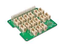 | |
| Consigue uno ahora | Consigue uno ahora | Consigue uno ahora |
Conexión de Hardware
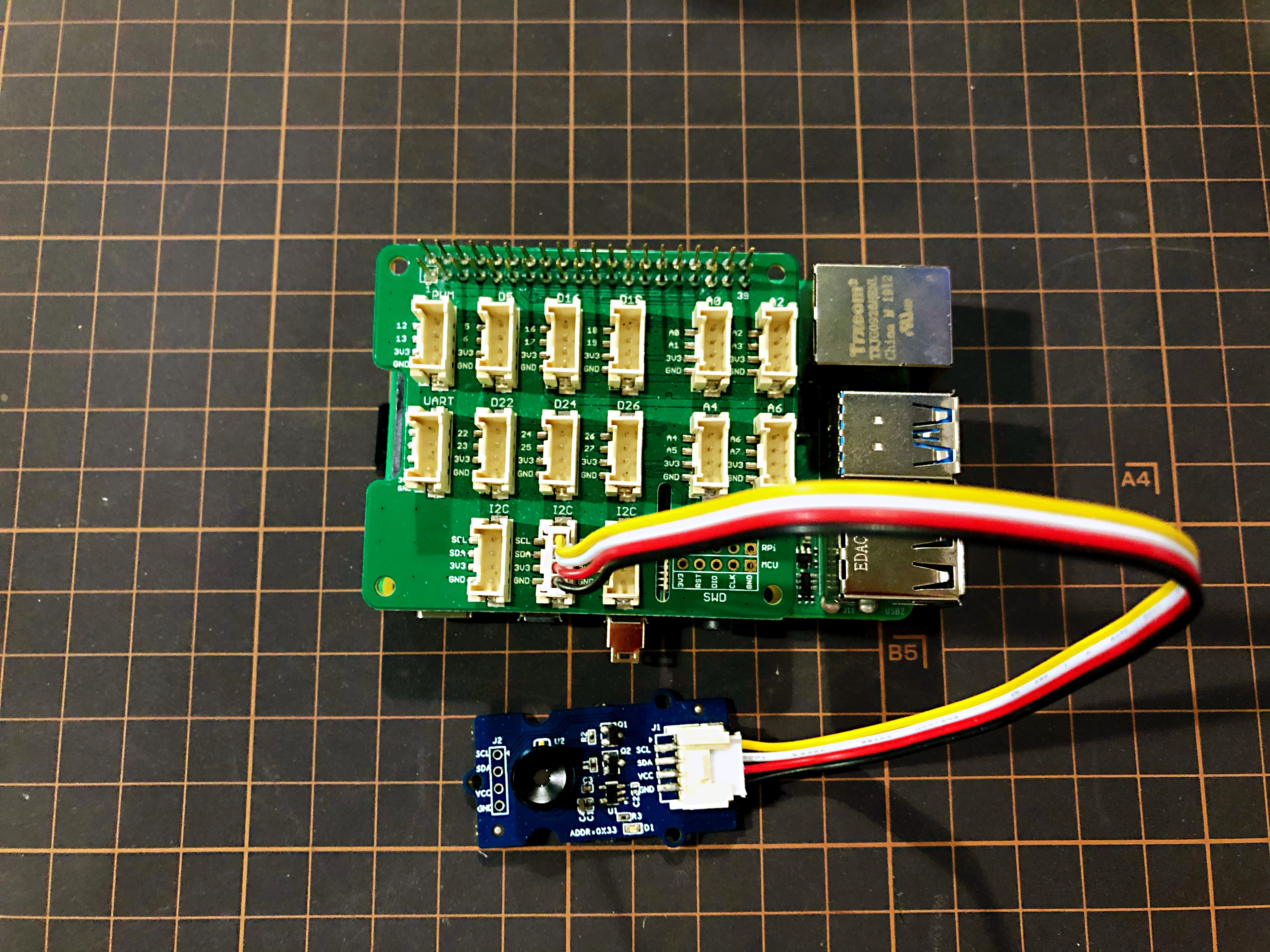
- Paso 1 Conecta la Grove - Thermal Imaging Camera a uno de los dos puertos I2C.
- Paso 2 Conecta la Raspberry Pi 4 al Grove Base Hat for Raspberry Pi.
- Paso 3 Conecta la Raspberry Pi a una pantalla mediante cable HDMI, y enciende la Raspberry Pi 4 por USB tipo-C.
Software
La Raspberry Pi 4 soporta Python, por lo que la demostración del proyecto puede mostrarse fácilmente desde la pantalla de la Raspberry Pi 4 si sigues los pasos a continuación.
- Paso 1 Instala grove.py mediante el comando
pip3 install Seeed-grove.py
- Paso 2 Instala el controlador MLX90641 con el siguiente comando. Entorno Python(Si no tienes autoridad en tu Raspberry Pi):
pip3 install seeed-python-mlx9064x
Actualizar al controlador más reciente:
pip3 install --upgrade seeed-python-mlx9064x
- Paso 3 Verifica el número i2c correspondiente de la Raspberry Pi:
ls /dev/i2c*
Puedes obtener un resultado como este:
/dev/i2c-1
-
Paso 4 Descarga la Librería MLX90641 mediante git clone con el comando.
-
Paso 5 Ejecuta el archivo BasicReadings.py con los siguientes comandos:
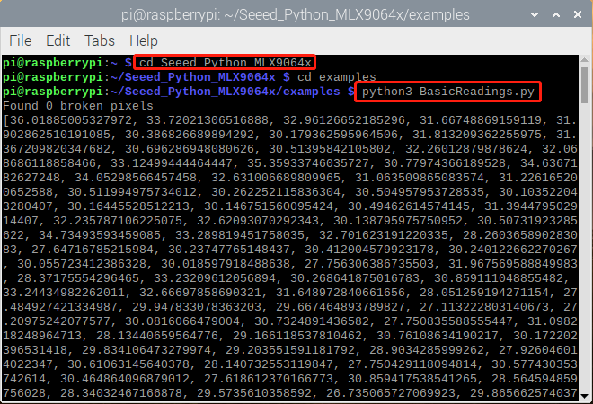
El resultado se mostrará como se ve arriba si todo va bien.
Se ha lanzado una interfaz de usuario mejorada del resultado en Raspberry Pi como se muestra a continuación:
- Paso 1 Instala pyqt5:
sudo apt-get install python3-pyqt5 -y
- Paso 2 Instalación desde PyPI:
sudo pip3 install seeed_python_ircamera
- Paso 3 Establece la velocidad máxima de i2c y luego reinicia:
sudo sh -c "echo dtparam=i2c_arm=on,i2c_arm_baudrate=400000 >> /boot/config.txt"
sudo reboot
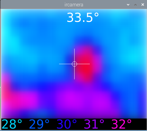
- Paso 4 Ingresa el siguiente comando en la terminal:
sudo ircamera I2C MLX90641
El resultado se mostrará como se indica a continuación si todo va bien.
Recursos
- [PDF] Hoja de datos del MLX90641
- [ZIP] Visualización MLX90641
Soporte Técnico y Discusión del Producto
Por favor envía cualquier problema técnico a nuestro foro.
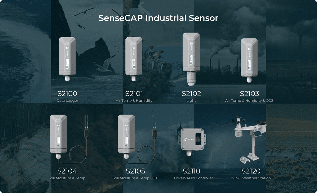
Actualizable a Sensores Industriales
Con el controlador S2110 y el registrador de datos S2100 de SenseCAP, puedes convertir fácilmente el Grove en un sensor LoRaWAN®. Seeed no solo te ayuda con la creación de prototipos, sino que también te ofrece la posibilidad de expandir tu proyecto con la serie SenseCAP de sensores industriales robustos.
La carcasa IP66, la configuración Bluetooth, la compatibilidad con la red global LoRaWAN®, la batería integrada de 19 Ah y el potente soporte de la APP hacen del SenseCAP S210x la mejor opción para aplicaciones industriales. La serie incluye sensores para humedad del suelo, temperatura y humedad del aire, intensidad de luz, CO2, EC, y una estación meteorológica 8 en 1. Prueba el último SenseCAP S210x para tu próximo proyecto industrial exitoso.