Desarrollar SenseCAP Indicator ambos chips con Arduino
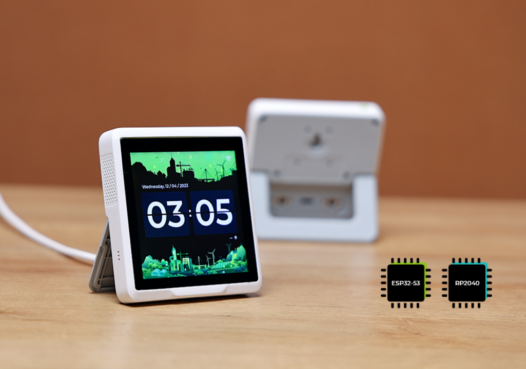
El SenseCAP Indicator es un dispositivo de pantalla táctil de 4 pulgadas que está alimentado por los MCUs duales ESP32 y RP2040. ESP32 y RP2040 son ambos microcontroladores altamente capaces que ofrecen una gama de características y funciones.
Este tutorial te guiará para desarrollar tu propio proyecto/firmware personalizado para el Sensecap Indicator usando la simplicidad y flexibilidad del Framework Arduino.
Preparación del Hardware
Estoy usando SenseCAP Indicator como el hardware aquí y hay cuatro tipos de sensores(CO2, Temp, Humi, TVOC) en él. Los contenidos aquí deben incluir:
| SenseCAP Indicator D1S |
|---|
 |
Descripción General del Hardware y Conocimiento de Desarrollo
El Indicator está diseñado con dos MCU donde están el RP2040 y el ESP32S3 trabajando al mismo tiempo.
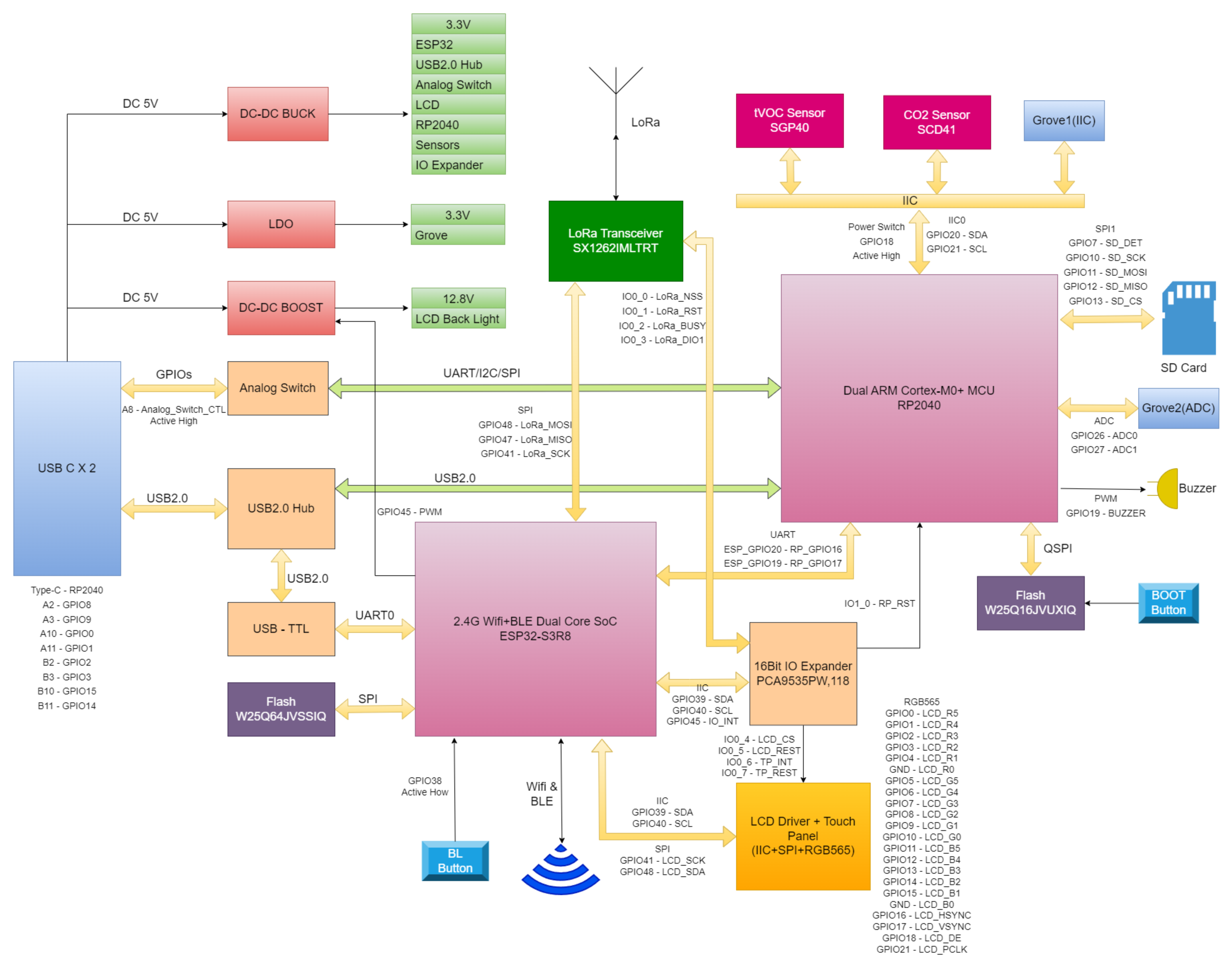
Basándonos en el diagrama anterior sabemos que:
- Todos los sensores están conectados al microcontrolador RP2040 usando protocolo I2C
- Hay un módulo expansor I2C IO usando el IC PCA9535
- La pantalla está conectada al microcontrolador ESP32S3 con 2 pines (CS, RESET) conectados al expansor I2C PCA9535
- El RP2040 está conectado al ESP32S3 a través del pin 20 y pin 19 en el ESP32S3 usando interfaces UART
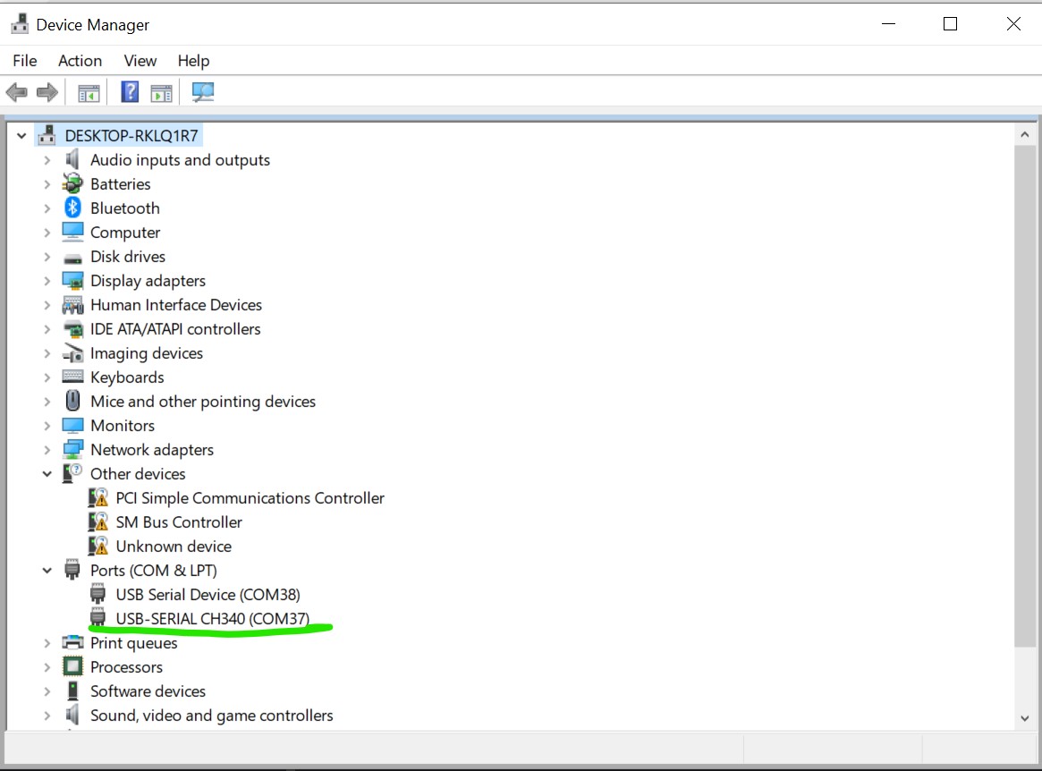
Por lo tanto, si el Sensecap Indicator se conecta a la computadora se te presentarán 2 puertos serie, uno para el RP2040 y uno para el ESP32S3. El que tiene la información USB-SERIAL CH340 es el que está conectado al ESP32S3 y este es el que se usará para el resto del tutorial.
Preparación del Software
Estamos usando Arduino aquí.
Antes de continuar con el tutorial, asegúrate de que los siguientes pasos estén completados en el Arduino IDE:
- Definición de placa ESP32: Asegúrate de que la definición de placa ESP32 esté instalada y actualizada a la última versión. Puedes seguir esta guía si la placa ESP32 aún no está en el Arduino IDE.
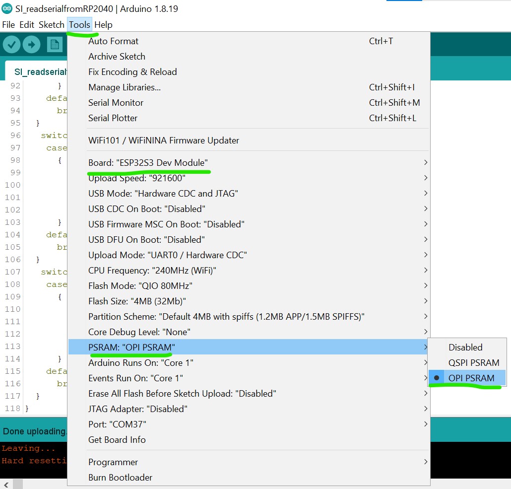
- Selección de placa: Elige el ESP32S3 Dev Module como la definición de placa.
- PSRAM: Habilita la función OPI PSRAM en el Arduino IDE para asegurar el funcionamiento adecuado de la pantalla.
Placas Utilizadas
Para asegurar compatibilidad con el proyecto, por favor usa las siguientes versiones de las placas:
- ESP32: versión 3.1.2
- Raspberry Pi Pico Arduino: versión 4.4.3
Librerías Utilizadas
TouchLib: versión 0.0.2
Para integrar el controlador táctil y unificar la interfaz táctil, se necesita la librería TouchLib. No está disponible en el Administrador de Librerías del Arduino IDE. Puedes descargarla manualmente desde el repositorio GitHub de TouchLib, y luego añadirla al Arduino IDE a través de Sketch > Include Library > Add .ZIP Library.
Después de que la librería sea descargada, abre el Arduino IDE, ve al menú Sketch, elige "Add .ZIP Library," y luego añade la librería descargada al IDE.
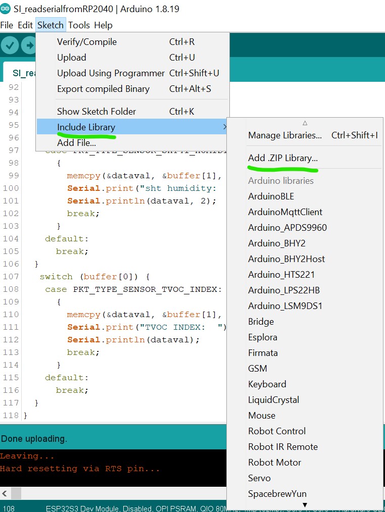
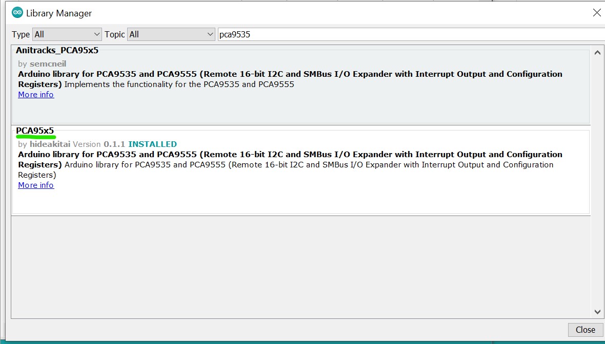
De manera similar, para una integración fluida, necesitas verificar el mismo menú sketch y seleccionar "Manage Libraries," luego buscar las librerías requeridas (ej., "PCA9535," elige la hecha por hidea kitai) e instalarlas, mientras aseguras las siguientes versiones para todas las otras librerías requeridas:
- Adafruit TinyUSB: versión 3.4.2
- Anitracks_PCA95x5: versión 0.1.3
- GFX Library for Arduino: versión 1.5.3
- PacketSerial: versión 1.4.0
- lvgl: versión 9.2.2
- PCA95x5: versión 0.1.3
Asegúrate de que estas librerías y placas estén instaladas en el Arduino IDE para evitar problemas de compatibilidad.
Comenzando
- Nuevo Tutorial (por LongDirtyAnimAlf)
- Tutorial Anterior (por Hendra)
Después de que todas las librerías necesarias estén instaladas, sube el código de abajo para probar si la pantalla está funcionando con el entorno Arduino. Puedes subir el código de abajo:
#include <Arduino_GFX_Library.h>
#include <PCA95x5.h>
#define GFX_BL DF_GFX_BL // default backlight pin, you may replace DF_GFX_BL to actual backlight pin

/* More dev device declaration: https://github.com/moononournation/Arduino_GFX/wiki/Dev-Device-Declaration */
#if defined(DISPLAY_DEV_KIT)
Arduino_GFX *gfx = create_default_Arduino_GFX();
#else /* !defined(DISPLAY_DEV_KIT) */

#define GFX_DEV_DEVICE ESP32_S3_RGB
#define GFX_BL 45
Arduino_DataBus *bus = new Arduino_SWSPI(
    GFX_NOT_DEFINED /* DC */, PCA95x5::Port::P04 /* CS */,
    41 /* SCK */, 48 /* MOSI */, GFX_NOT_DEFINED /* MISO */);

// option 1:
// Uncomment for 4" rect display
Arduino_ESP32RGBPanel *rgbpanel = new Arduino_ESP32RGBPanel(
    18 /* DE */, 17 /* VSYNC */, 16 /* HSYNC */, 21 /* PCLK */,
    4 /* R0 */, 3 /* R1 */, 2 /* R2 */, 1 /* R3 */, 0 /* R4 */,
    10 /* G0 */, 9 /* G1 */, 8 /* G2 */, 7 /* G3 */, 6 /* G4 */, 5 /* G5 */,
    15 /* B0 */, 14 /* B1 */, 13 /* B2 */, 12 /* B3 */, 11 /* B4 */,
    1 /* hsync_polarity */, 10 /* hsync_front_porch */, 8 /* hsync_pulse_width */, 50 /* hsync_back_porch */,
    1 /* vsync_polarity */, 10 /* vsync_front_porch */, 8 /* vsync_pulse_width */, 20 /* vsync_back_porch */);
Arduino_RGB_Display *gfx = new Arduino_RGB_Display(
    480 /* width */, 480 /* height */, rgbpanel, 2 /* rotation */, true /* auto_flush */,
    bus, GFX_NOT_DEFINED /* RST */, st7701_type1_init_operations, sizeof(st7701_type1_init_operations));

#endif /* !defined(DISPLAY_DEV_KIT) */
/*******************************************************************************
 * End of Arduino_GFX setting
 ******************************************************************************/

void setup(void)
{
  Serial.begin(115200);
  // Serial.setDebugOutput(true);
  // while(!Serial);
  Serial.println("Arduino_GFX Hello World example");

#ifdef GFX_EXTRA_PRE_INIT
  GFX_EXTRA_PRE_INIT();
#endif

  // Init Display
  if (!gfx->begin())
  {
    Serial.println("gfx->begin() failed!");
  }
  gfx->fillScreen(BLACK);

#ifdef GFX_BL
  pinMode(GFX_BL, OUTPUT);
  digitalWrite(GFX_BL, HIGH);
#endif

  gfx->setCursor(10, 10);
  gfx->setTextColor(RED);
  gfx->println("Sensecap Indicator");

  delay(5000); // 5 seconds
}

void loop()
{
  gfx->setCursor(random(gfx->width()), random(gfx->height()));
  gfx->setTextColor(random(0xffff), random(0xffff));
  gfx->setTextSize(random(6) /* x scale */, random(6) /* y scale */, random(2) /* pixel_margin */);
  gfx->println("Sensecap Indicator");

  delay(1000); // 1 second
}
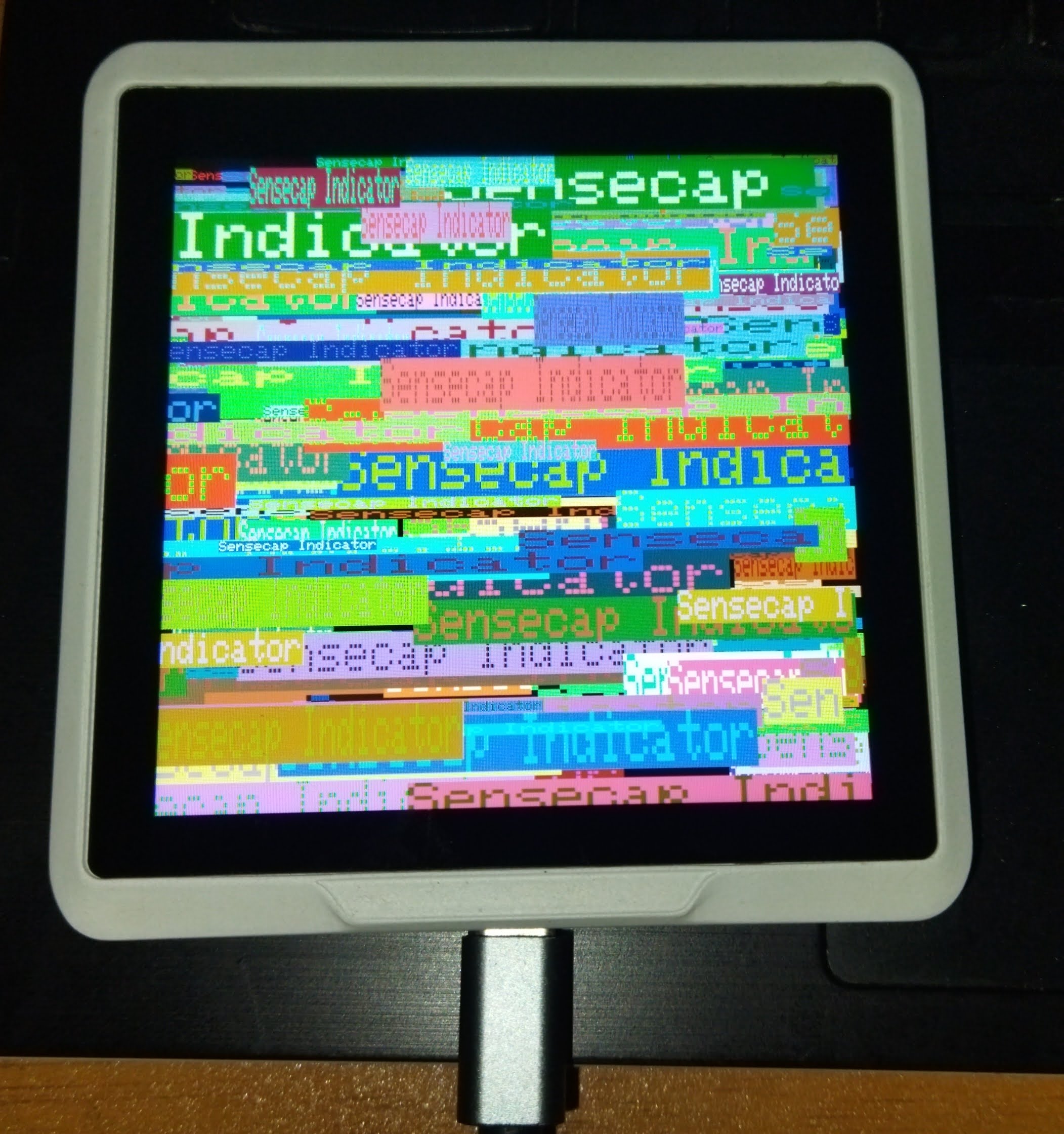
Si todo va bien, se imprimirá aleatoriamente un texto "Sensecap Indicator" en la pantalla.
Creando Aplicaciones GUI Simples con SenseCap Indicator
El SenseCap Indicator tiene un potente microcontrolador ESP32-S3 y una pantalla de alta resolución de 480x480 que lo hace ideal para crear interfaces gráficas de usuario. Ahora, continuaremos nuestro desarrollo con el SenseCap Indicator explorando cómo crear aplicaciones GUI interactivas usando LVGL. Puedes descargar el proyecto completo incluyendo código fuente y archivos de cabecera desde el repositorio: Descargar Proyecto LVGL de SenseCap Indicator
Después de descargar y extraer los archivos del proyecto, sube el siguiente código para crear una aplicación GUI básica de múltiples pantallas:
/*Using LVGL with Arduino requires some extra steps:
 *Be sure to read the docs here: https://docs.lvgl.io/master/get-started/platforms/arduino.html
 Install: lvgl*/

// This define is sometimes missing when using old ESP32-IDF version
//#define ESP_INTR_CPU_AFFINITY_AUTO 0

#include <Arduino.h>
#include <lvgl.h>
#include <Arduino_GFX_Library.h>
#include <PacketSerial.h>
#include "Indicator_Extender.h"
#include "Indicator_SWSPI.h"
#include "ui.h"
#include "touch.h"

#define HOR_RES 480
#define VER_RES 480

#define PACKET_UART_RXD 20
#define PACKET_UART_TXD 19

#define BUTTON_PIN 38

#define GFX_DEV_DEVICE ESP32_S3_RGB
#define RGB_PANEL
#define GFX_BL 45
Arduino_DataBus *bus = new Indicator_SWSPI(
    GFX_NOT_DEFINED /* DC */, EXPANDER_IO_LCD_CS /* CS */,
    SPI_SCLK /* SCK */, SPI_MOSI /* MOSI */, GFX_NOT_DEFINED /* MISO */);

Arduino_ESP32RGBPanel *rgbpanel = new Arduino_ESP32RGBPanel(
    18 /* DE */, 17 /* VSYNC */, 16 /* HSYNC */, 21 /* PCLK */,
    4 /* R0 */, 3 /* R1 */, 2 /* R2 */, 1 /* R3 */, 0 /* R4 */,
    10 /* G0 */, 9 /* G1 */, 8 /* G2 */, 7 /* G3 */, 6 /* G4 */, 5 /* G5 */,
    15 /* B0 */, 14 /* B1 */, 13 /* B2 */, 12 /* B3 */, 11 /* B4 */,
    1 /* hsync_polarity */, 10 /* hsync_front_porch */, 8 /* hsync_pulse_width */, 50 /* hsync_back_porch */,
    1 /* vsync_polarity */, 10 /* vsync_front_porch */, 8 /* vsync_pulse_width */, 20 /* vsync_back_porch */);
Arduino_RGB_Display *gfx = new Arduino_RGB_Display(
    HOR_RES /* width */, VER_RES /* height */, rgbpanel, 0 /* rotation */, false /* auto_flush */,
    bus, GFX_NOT_DEFINED /* RST */, st7701_indicator_init_operations, sizeof(st7701_indicator_init_operations));


COBSPacketSerial myPacketSerial;

void onPacketReceived(const uint8_t* buffer, size_t size);

uint32_t millis_cb(void)
{
  return millis();
}

/*Read the touchpad*/
void my_touchpad_read(lv_indev_t *indev, lv_indev_data_t *data)
{
  if (touch_has_signal())
  {
    if (touch_touched())
    {
      data->state = LV_INDEV_STATE_PRESSED;

      /*Set the coordinates*/
      data->point.x = touch_last_x;
      data->point.y = touch_last_y;
    }
    else if (touch_released())
    {
      data->state = LV_INDEV_STATE_RELEASED;
    }
  }
  else
  {
    data->state = LV_INDEV_STATE_RELEASED;
  }
}

// Main buttons event handler
static void event_handler(lv_event_t * e)
{
  lv_event_code_t code = lv_event_get_code(e);
  lv_obj_t * btn = lv_event_get_current_target_obj(e);

  if (btn != NULL)
  {
    if(code == LV_EVENT_CLICKED)
    {
      void * btn_no_void = (void*)lv_event_get_user_data(e);
      byte btn_no = (byte)((uintptr_t)btn_no_void);
      lv_obj_t * screen = lv_obj_get_screen(btn);
      if (screen != NULL)
      {
        Serial.println("Screen assigned");
        if (screen == screen2)
        {
          Serial.println("Screen 2");
          if (btn_no != 0)
          {
            Create_Screen3(event_handler);
            lv_screen_load(screen3);
          }
        }
        if (screen == screen3)
        {
          Serial.println("Screen 3");
          if (btn_no == 0)
          {
            lv_screen_load(screen2);
            lv_obj_delete(screen3);
          }
        }
      }
    }
  }
}

void setup()
{
  Serial.begin(115200);
  Serial.println("SenseCap Indicator startup");
  String LVGL_Arduino = String('V') + lv_version_major() + "." + lv_version_minor() + "." + lv_version_patch();
  Serial.println(LVGL_Arduino);

  pinMode(BUTTON_PIN, INPUT);

  // Init Indicator hardware
  extender_init();

  myPacketSerial.begin(115200);
  Serial1.begin(115200, SERIAL_8N1, PACKET_UART_RXD, PACKET_UART_TXD);
  myPacketSerial.setStream(&Serial1);
  myPacketSerial.setPacketHandler(&onPacketReceived);

  // Init Display
  if (!gfx->begin(12000000L))
  {
    Serial.println("gfx->begin() failed!");
    Serial.println("Expect sever errors !!!");
  }
  gfx->fillScreen(RGB565_BLACK);

#ifdef GFX_BL
  pinMode(GFX_BL, OUTPUT);
  digitalWrite(GFX_BL, HIGH);
#endif
  lv_init();

  /*Set a tick source so that LVGL will know how much time elapsed. */
  lv_tick_set_cb(millis_cb);

  /* register print function for debugging */
#if LV_USE_LOG != 0
  lv_log_register_print_cb(my_print);
#endif

  lv_screen_init(gfx, HOR_RES, VER_RES);
  //lv_display_set_rotation(disp, LV_DISPLAY_ROTATION_0);
  //lv_display_set_antialiasing(disp,false);

  // Init touch device
  touch_init(HOR_RES, VER_RES, 0); // rotation will be handled by lvgl
  /*Initialize the input device driver*/
  lv_indev_t *indev = lv_indev_create();
  lv_indev_set_type(indev, LV_INDEV_TYPE_POINTER); /*Touchpad should have POINTER type*/
  lv_indev_set_read_cb(indev, my_touchpad_read);

  Screen2Create(event_handler);

  lv_screen_load(screen2);

  Serial.println("Setup done");
}

void loop()
{
  static TickType_t xLastWakeTime = xTaskGetTickCount();

  /*
  unsigned long startTime = millis();
  while (digitalRead(BUTTON_PIN) == LOW)
  {
    if (millis() - startTime >= 10000)
    {
      ESP.restart();
      //esp_restart();
    }
  }
  */

  myPacketSerial.update();
  // Check for a receive buffer overflow (optional).
  if (myPacketSerial.overflow())
  {
    // Send an alert via a pin (e.g. make an overflow LED) or return a
    // user-defined packet to the sender.
  }

  lv_task_handler(); /* let the GUI do its work */

  // Simple delay always 5ms
  //delay(5);

  // This delay will adapt to the time consumed in the above tasks
  // If these tasks consume time, it will delay shorter
  vTaskDelayUntil( &xLastWakeTime, ( 5 / portTICK_PERIOD_MS ) );
}

void onPacketReceived(const uint8_t* buffer, size_t size)
{
  if (size < 1) {
    return;
  }

  byte index = 0;
  byte Command = buffer[index++];
  if (Command == 0x55)
  {
    long Temperature = 0;
    long Humidity = 0;

    memcpy(&Temperature, &buffer[index], sizeof(Temperature));
    index += sizeof(Temperature);
    memcpy(&Humidity, &buffer[index], sizeof(Humidity));
    index += sizeof(Humidity);

    Screen2AddData(Temperature,Humidity);
  }
}
Después de cargar el código, abre el Monitor Serie y establece la velocidad de baudios a 115200. Deberías ver mensajes de inicialización y tu GUI aparecerá en la pantalla, mostrando Screen2 con cualquier dato de temperatura y humedad recibido a través de la conexión UART.
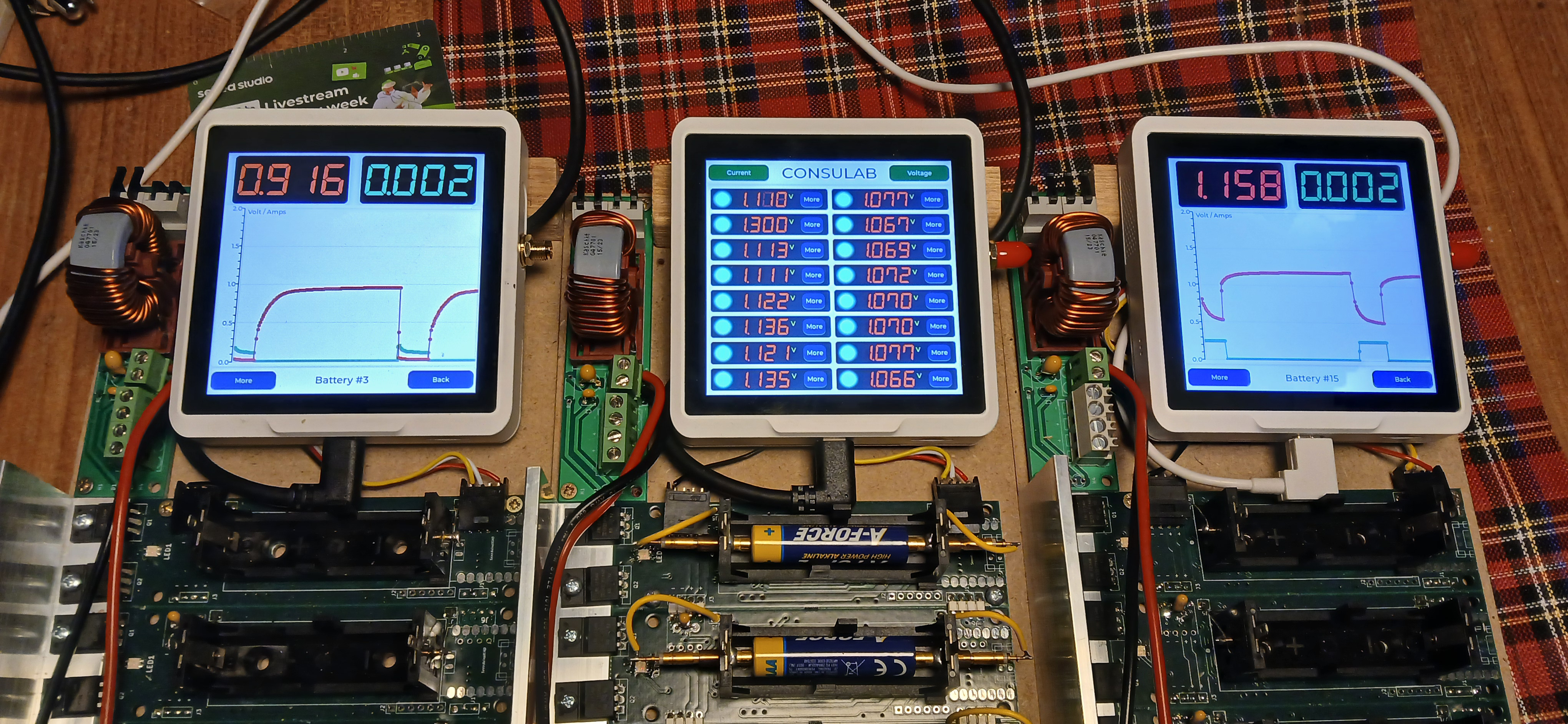
Aplicación GUI Avanzada con Múltiples Pantallas y Visualización de Datos
El segundo ejemplo se basa en la aplicación básica añadiendo características más sofisticadas incluyendo monitoreo de batería, visualización dinámica de datos e indicadores de estado codificados por colores. Puedes descargar el proyecto completo incluyendo código fuente y archivos de cabecera desde el repositorio: Descargar Proyecto SenseCap Indicator LVGL
Para implementar esta versión, carga el siguiente código:
/*Using LVGL with Arduino requires some extra steps:
 *Be sure to read the docs here: https://docs.lvgl.io/master/get-started/platforms/arduino.html
 Install: lvgl*/

// This define is sometimes missing when using old ESP32-IDF version
//#define ESP_INTR_CPU_AFFINITY_AUTO 0

#include <Arduino.h>
#include <lvgl.h>
#include <Arduino_GFX_Library.h>
#include <PacketSerial.h>
#include "Indicator_Extender.h"
#include "Indicator_SWSPI.h"
#include "ui.h"
#include "touch.h"
#include "shared.h"

#define HOR_RES 480
#define VER_RES 480

#define PACKET_UART_RXD 20
#define PACKET_UART_TXD 19

#define BUTTON_PIN 38

#define GFX_DEV_DEVICE ESP32_S3_RGB
#define RGB_PANEL
#define GFX_BL 45
Arduino_DataBus *bus = new Indicator_SWSPI(
    GFX_NOT_DEFINED /* DC */, EXPANDER_IO_LCD_CS /* CS */,
    SPI_SCLK /* SCK */, SPI_MOSI /* MOSI */, GFX_NOT_DEFINED /* MISO */);

Arduino_ESP32RGBPanel *rgbpanel = new Arduino_ESP32RGBPanel(
    18 /* DE */, 17 /* VSYNC */, 16 /* HSYNC */, 21 /* PCLK */,
    4 /* R0 */, 3 /* R1 */, 2 /* R2 */, 1 /* R3 */, 0 /* R4 */,
    10 /* G0 */, 9 /* G1 */, 8 /* G2 */, 7 /* G3 */, 6 /* G4 */, 5 /* G5 */,
    15 /* B0 */, 14 /* B1 */, 13 /* B2 */, 12 /* B3 */, 11 /* B4 */,
    1 /* hsync_polarity */, 10 /* hsync_front_porch */, 8 /* hsync_pulse_width */, 50 /* hsync_back_porch */,
    1 /* vsync_polarity */, 10 /* vsync_front_porch */, 8 /* vsync_pulse_width */, 20 /* vsync_back_porch */);
Arduino_RGB_Display *gfx = new Arduino_RGB_Display(
    HOR_RES /* width */, VER_RES /* height */, rgbpanel, 0 /* rotation */, false /* auto_flush */,
    bus, GFX_NOT_DEFINED /* RST */, st7701_indicator_init_operations, sizeof(st7701_indicator_init_operations));

TBatteryBoard BatteryBoards[DAUGHTERBOARDCOUNT] = {0};

COBSPacketSerial myPacketSerial;
//PacketSerial_<COBS, 0, 1024> myPacketSerial;

void onPacketReceived(const uint8_t* buffer, size_t size);

#if LV_USE_LOG != 0
void my_print(lv_log_level_t level, const char *buf)
{
  LV_UNUSED(level);
  Serial.println(buf);
  Serial.flush();
}
#endif

uint32_t millis_cb(void)
{
  return millis();
}

/*Read the touchpad*/
void my_touchpad_read(lv_indev_t *indev, lv_indev_data_t *data)
{
  if (touch_has_signal())
  {
    if (touch_touched())
    {
      data->state = LV_INDEV_STATE_PRESSED;

      /*Set the coordinates*/
      data->point.x = touch_last_x;
      data->point.y = touch_last_y;
    }
    else if (touch_released())
    {
      data->state = LV_INDEV_STATE_RELEASED;
    }
  }
  else
  {
    data->state = LV_INDEV_STATE_RELEASED;
  }
}

static void event_handler(lv_event_t * e)
{
  lv_event_code_t code = lv_event_get_code(e);
  lv_obj_t * btn = lv_event_get_current_target_obj(e);

  if (btn != NULL)
  {
    if(code == LV_EVENT_CLICKED)
    {
      void * btn_no_void = (void*)lv_event_get_user_data(e);
      byte btn_no = (byte)((uintptr_t)btn_no_void);
      lv_obj_t * screen = lv_obj_get_screen(btn);
      if (screen != NULL)
      {
        Serial.println("Screen assigned");

        if (screen == screen1)
        {
          Serial.println("Screen 1");
          Screen2SetActive(btn_no);
          lv_screen_load(screen2);
          //Screen2SetActive(5);
        }
        if (screen == screen2)
        {
          Serial.println("Screen 2");
          if (btn_no == 0)
          {
            lv_screen_load(screen1);
          }
          else
          {
            Create_Screen3(event_handler);
            lv_screen_load(screen3);
          }
        }
        if (screen == screen3)
        {
          Serial.println("Screen 3");
          if (btn_no == 0)
          {
            lv_screen_load(screen2);
            lv_obj_delete(screen3);
          }
        }
      }
    }
  }
}

void setup()
{
  Serial.begin(115200);
  // Serial.setDebugOutput(true);
  // while(!Serial);
  Serial.println("SenseCap Indicator startup");
  String LVGL_Arduino = String('V') + lv_version_major() + "." + lv_version_minor() + "." + lv_version_patch();
  Serial.println(LVGL_Arduino);

  pinMode(BUTTON_PIN, INPUT);

  // Init Indicator hardware
  extender_init();

  myPacketSerial.begin(115200);
  Serial1.begin(115200, SERIAL_8N1, PACKET_UART_RXD, PACKET_UART_TXD);
  myPacketSerial.setStream(&Serial1);
  myPacketSerial.setPacketHandler(&onPacketReceived);

  // Init Display
  if (!gfx->begin(12000000L))
  {
    Serial.println("gfx->begin() failed!");
    Serial.println("Expect sever errors !!!");
  }
  gfx->fillScreen(RGB565_BLACK);

#ifdef GFX_BL
  pinMode(GFX_BL, OUTPUT);
  digitalWrite(GFX_BL, HIGH);
#endif
  lv_init();

  /*Set a tick source so that LVGL will know how much time elapsed. */
  lv_tick_set_cb(millis_cb);

  /* register print function for debugging */
#if LV_USE_LOG != 0
  lv_log_register_print_cb(my_print);
#endif

  lv_screen_init(gfx, HOR_RES, VER_RES);
  //lv_display_set_rotation(disp, LV_DISPLAY_ROTATION_0);
  //lv_display_set_antialiasing(disp,false);

  // Init touch device
  touch_init(HOR_RES, VER_RES, 0); // rotation will be handled by lvgl
  /*Initialize the input device driver*/
  lv_indev_t *indev = lv_indev_create();
  lv_indev_set_type(indev, LV_INDEV_TYPE_POINTER); /*Touchpad should have POINTER type*/
  lv_indev_set_read_cb(indev, my_touchpad_read);

  Create_Screen1(event_handler);

  Screen2Create(event_handler);
  Screen2InitData();

  lv_screen_load(screen1);

  Serial.println("Setup done");
}

void loop()
{
  static TickType_t xLastWakeTime = xTaskGetTickCount();

  /*
  unsigned long startTime = millis();
  while (digitalRead(BUTTON_PIN) == LOW)
  {
    if (millis() - startTime >= 10000)
    {
      ESP.restart();
      //esp_restart();
    }
  }
  */

  myPacketSerial.update();
  // Check for a receive buffer overflow (optional).
  if (myPacketSerial.overflow())
  {
    // Send an alert via a pin (e.g. make an overflow LED) or return a
    // user-defined packet to the sender.
  }

  lv_task_handler(); /* let the GUI do its work */

  // Simple delay always 5ms
  //delay(5);

  // This delay will adapt to the time consumed in the above tasks
  // If these tasks consume time, it will delay shorter
  vTaskDelayUntil( &xLastWakeTime, ( 5 / portTICK_PERIOD_MS ) );
}

void onPacketReceived(const uint8_t* buffer, size_t size)
{
#ifndef YOLO
  Serial.printf("<--- recv len:%d, data: ", size);
  for (int i = 0; i < size; i++) {
    Serial.printf("0x%x ", buffer[i]);
  }
  Serial.println("");
#endif


  if (size < 1) {
    return;
  }

  byte index = 0;

  TCommands Command = (TCommands)buffer[index++];

  if ((Command == CMD_get_data) || (Command == CMD_set_value))
  {
    byte BatteryNumber = buffer[index++];

    if (Command == CMD_get_data)
    {
      dword tempcalc;
      word Volt = 0;
      word Amps = 0;

      memcpy(&Volt, &buffer[index], 2);
      index += 2;
      memcpy(&Amps, &buffer[index], 2);
      index += 2;

      Screen2AddData((BatteryNumber+1),Volt,Amps);

      // Put data on screen 1
      tempcalc = Volt * 3300u;
      tempcalc /= (dword)((1u << BITS)-1u);
      SetVoltageScreen1mV(BatteryNumber,(word)tempcalc);

      tempcalc = Amps * 6000u;
      tempcalc /= (dword)((1u << BITS)-1u);
      SetCurrentScreen1mA(BatteryNumber,(word)tempcalc);
    }

    if (Command == CMD_set_value)
    {
      lv_color_t c = LV_COLOR_MAKE(0,0,0);
      TBatteryStatus Status = (TBatteryStatus)buffer[index++];
      switch (Status)
      {
        case BSCurrent:
        case BSPower:
        case BSResistor:
        {
          c = lv_palette_main(LV_PALETTE_DEEP_ORANGE);
          break;
        }
        case BSCharge:
        case BSVoltage:
        case BSPulse:
        {
          c = lv_palette_main(LV_PALETTE_PURPLE);
          break;
        }
        case BSOff:
        {
          c = LV_COLOR_MAKE(0X00,0xFF,0xFF);
          break;
        }
        default:
        {
          c = lv_palette_main(LV_PALETTE_YELLOW);
        }
      }
      SetLedScreen1(BatteryNumber,c);
    }
  }
}
Con este código, el SenseCap Indicator mostrará una aplicación de tres pantallas. La Pantalla1 muestra una vista general de los datos de la batería con indicadores de estado codificados por colores, la Pantalla2 proporciona información detallada para baterías individuales, y la Pantalla3 ofrece controles adicionales o información.
Ahora podemos desarrollar con la pantalla que se conecta al chip ESP32S3 y leer los sensores que se vinculan al chip RP2040. Finalmente combinar ambos.
Desarrollar con una Pantalla Conectada al Chip ESP32-S3
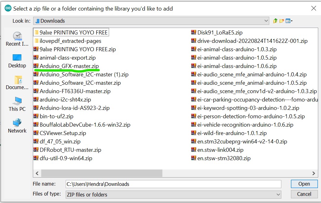
El Sensecap Indicator está usando el módulo ST7701 para la pantalla y utiliza interfaces paralelas y ya está conectado a los pines en el MCU ESP32S3. Para poder controlar la pantalla se necesitan algunas librerías de arduino. Puedes descargar aquí
Después de que la librería sea descargada abre el Arduino, en el menú sketch elige agregar librería zip
Agrega la librería descargada al IDE de Arduino.
Mientras tanto, necesitas verificar el mismo menú sketch y elegir "administrar librerías" luego buscar "PCA9535" y elegir la hecha por hidea kitai luego instalarla
La librería PCA9535 es necesaria porque el pin CS del ST7701 está conectado al módulo expansor i2c PCA9535. Específicamente el Pin 4 del módulo i2c.
Después de que todas las librerías necesarias estén instaladas sube el código de abajo para probar si la pantalla está funcionando con el entorno de Arduino. Puedes subir el código de abajo:
#include <Arduino_GFX_Library.h>
#include <PCA95x5.h>
#define GFX_BL DF_GFX_BL // default backlight pin, you may replace DF_GFX_BL to actual backlight pin

/* More dev device declaration: https://github.com/moononournation/Arduino_GFX/wiki/Dev-Device-Declaration */
#if defined(DISPLAY_DEV_KIT)
Arduino_GFX *gfx = create_default_Arduino_GFX();
#else /* !defined(DISPLAY_DEV_KIT) */

#define GFX_DEV_DEVICE ESP32_S3_RGB
#define GFX_BL 45
Arduino_DataBus *bus = new Arduino_SWSPI(
    GFX_NOT_DEFINED /* DC */, PCA95x5::Port::P04 /* CS */,
    41 /* SCK */, 48 /* MOSI */, GFX_NOT_DEFINED /* MISO */);

// option 1:
// Uncomment for 4" rect display
Arduino_ESP32RGBPanel *rgbpanel = new Arduino_ESP32RGBPanel(
    18 /* DE */, 17 /* VSYNC */, 16 /* HSYNC */, 21 /* PCLK */,
    4 /* R0 */, 3 /* R1 */, 2 /* R2 */, 1 /* R3 */, 0 /* R4 */,
    10 /* G0 */, 9 /* G1 */, 8 /* G2 */, 7 /* G3 */, 6 /* G4 */, 5 /* G5 */,
    15 /* B0 */, 14 /* B1 */, 13 /* B2 */, 12 /* B3 */, 11 /* B4 */,
    1 /* hsync_polarity */, 10 /* hsync_front_porch */, 8 /* hsync_pulse_width */, 50 /* hsync_back_porch */,
    1 /* vsync_polarity */, 10 /* vsync_front_porch */, 8 /* vsync_pulse_width */, 20 /* vsync_back_porch */);
Arduino_RGB_Display *gfx = new Arduino_RGB_Display(
    480 /* width */, 480 /* height */, rgbpanel, 2 /* rotation */, true /* auto_flush */,
    bus, GFX_NOT_DEFINED /* RST */, st7701_type1_init_operations, sizeof(st7701_type1_init_operations));

#endif /* !defined(DISPLAY_DEV_KIT) */
/*******************************************************************************
 * End of Arduino_GFX setting
 ******************************************************************************/

void setup(void)
{
  Serial.begin(115200);
  // Serial.setDebugOutput(true);
  // while(!Serial);
  Serial.println("Arduino_GFX Hello World example");

#ifdef GFX_EXTRA_PRE_INIT
  GFX_EXTRA_PRE_INIT();
#endif

  // Init Display
  if (!gfx->begin())
  {
    Serial.println("gfx->begin() failed!");
  }
  gfx->fillScreen(BLACK);

#ifdef GFX_BL
  pinMode(GFX_BL, OUTPUT);
  digitalWrite(GFX_BL, HIGH);
#endif

  gfx->setCursor(10, 10);
  gfx->setTextColor(RED);
  gfx->println("Sensecap Indicator");

  delay(5000); // 5 seconds
}

void loop()
{
  gfx->setCursor(random(gfx->width()), random(gfx->height()));
  gfx->setTextColor(random(0xffff), random(0xffff));
  gfx->setTextSize(random(6) /* x scale */, random(6) /* y scale */, random(2) /* pixel_margin */);
  gfx->println("Sensecap Indicator");

  delay(1000); // 1 second
}
Si todo va bien, se imprimirá aleatoriamente un texto "Sensecap Indicator" en la pantalla.
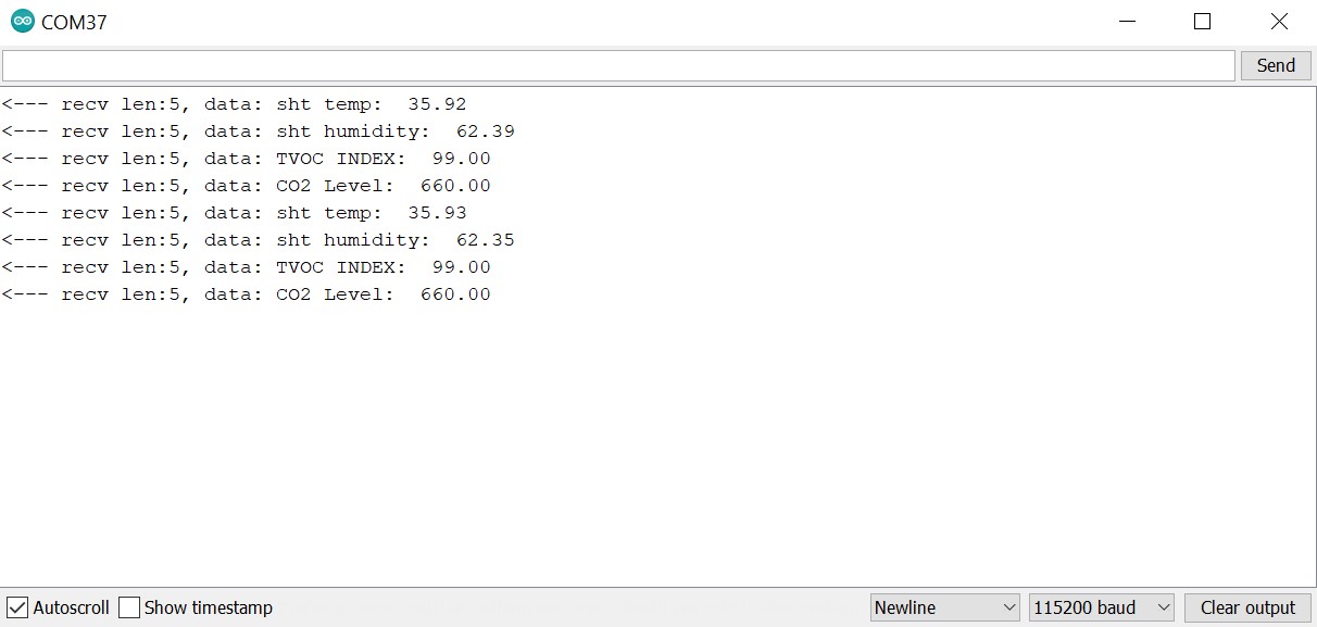
Leer los sensores que están conectados al chip RP2040
Como se mencionó anteriormente en la sección de preparación, todos los sensores están conectados al RP2040. Asumiendo que aún tienes el firmware predeterminado en el RP2040, los datos del sensor se envían al ESP32S3 usando la interfaz UART.
Para que el ESP32S3 pueda leer los datos, es necesario instalar una biblioteca llamada PacketSerial.
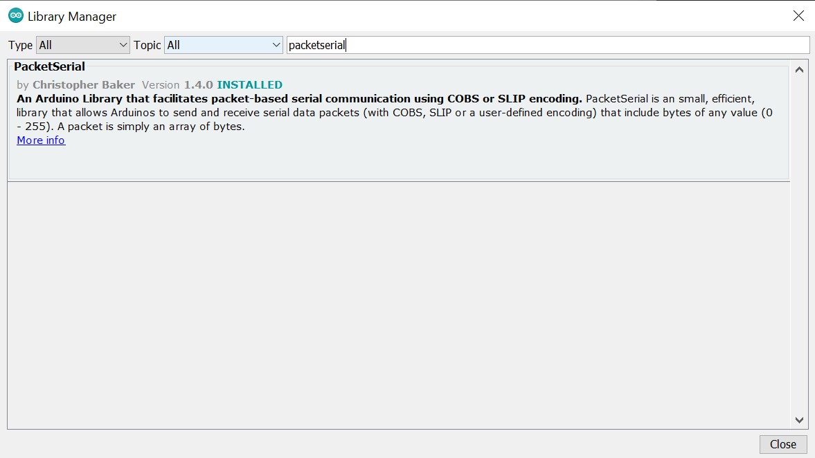
Después de que la biblioteca esté instalada, puedes cargar el código de abajo para obtener los datos del sensor en el ESP32S3:
//
// Copyright (c) 2012 Christopher Baker <https://christopherbaker.net>
//
// SPDX-License-Identifier: MIT
//


#include <PacketSerial.h>

PacketSerial myPacketSerial;

#define RXD2 20
#define TXD2 19

#define PKT_TYPE_SENSOR_SCD41_CO2 0XB2
#define PKT_TYPE_SENSOR_SHT41_TEMP 0XB3
#define PKT_TYPE_SENSOR_SHT41_HUMIDITY 0XB4
#define PKT_TYPE_SENSOR_TVOC_INDEX 0XB5
#define DEBUG   0

void setup()
{
  // We begin communication with our PacketSerial object by setting the
  // communication speed in bits / second (baud).
  myPacketSerial.begin(115200);

  // If we want to receive packets, we must specify a packet handler function.
  // The packet handler is a custom function with a signature like the
  // onPacketReceived function below.

  Serial1.begin(115200, SERIAL_8N1, RXD2, TXD2);
  myPacketSerial.setStream(&Serial1);
  myPacketSerial.setPacketHandler(&onPacketReceived);
}


void loop()
{
  // Do your program-specific loop() work here as usual.

  // The PacketSerial::update() method attempts to read in any incoming serial
  // data and emits received and decoded packets via the packet handler
  // function specified by the user in the void setup() function.
  //
  // The PacketSerial::update() method should be called once per loop(). Failure
  // to call the PacketSerial::update() frequently enough may result in buffer
  // serial overflows.
  myPacketSerial.update();

  // Check for a receive buffer overflow (optional).
  if (myPacketSerial.overflow())
  {
    // Send an alert via a pin (e.g. make an overflow LED) or return a
    // user-defined packet to the sender.
    //
    // Ultimately you may need to just increase your recieve buffer via the
    // template parameters (see the README.md).
  }
}


void onPacketReceived(const uint8_t *buffer, size_t size) {


  Serial.printf("<--- recv len:%d, data: ", size);


  if (size < 1) {
    return;
  }
  //byte serbytes[] = buffer[i];
  float dataval;
  switch (buffer[0]) {
    case PKT_TYPE_SENSOR_SCD41_CO2:
      {
        memcpy(&dataval, &buffer[1], sizeof(float));
        Serial.print("CO2 Level:  ");
        Serial.println(dataval);
        break;
      }
    default:
      break;
  }
   switch (buffer[0]) {
    case PKT_TYPE_SENSOR_SHT41_TEMP:
      {
        memcpy(&dataval, &buffer[1], sizeof(float));
        Serial.print("sht temp:  ");
        Serial.println(dataval, 2);
        break;
      }
    default:
      break;
  }
   switch (buffer[0]) {
    case PKT_TYPE_SENSOR_SHT41_HUMIDITY:
      {
        memcpy(&dataval, &buffer[1], sizeof(float));
        Serial.print("sht humidity:  ");
        Serial.println(dataval, 2);
        break;
      }
    default:
      break;
  }
   switch (buffer[0]) {
    case PKT_TYPE_SENSOR_TVOC_INDEX:
      {
        memcpy(&dataval, &buffer[1], sizeof(float));
        Serial.print("TVOC INDEX:  ");
        Serial.println(dataval);
        break;
      }
    default:
      break;
  }
}
Haz clic y abre el Monitor Serie y establece la Velocidad de Baudios a 115200, entonces se te presentarán los datos de los sensores del RP2040
Combina dos ejemplos y muestra los datos de los sensores en la pantalla
Abre el menú de ejemplos en el IDE de Arduino y dirígete a GFX library for Arduino luego elige el ejemplo SI_displaysensordata y súbelo.
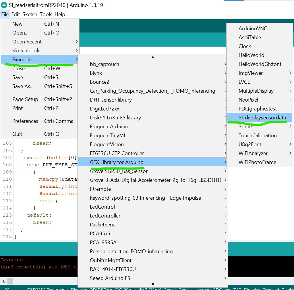
Si se sube exitosamente se te presentarán los datos de los sensores mostrados en la pantalla.
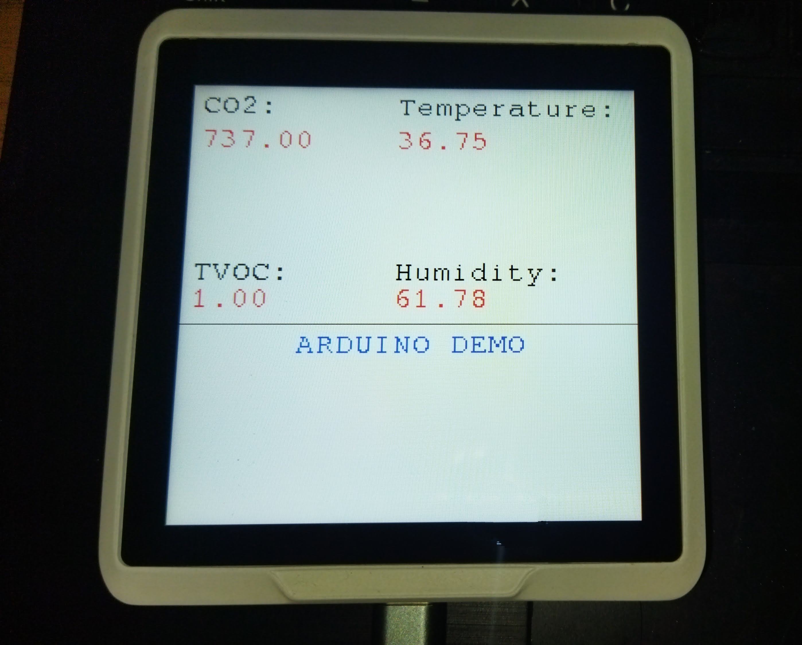
¡Felicitaciones, ahora puedes desarrollar el Sensecap Indicator usando el IDE de Arduino!
Qué Más
- Esto sigue siendo la FASE UNO para el desarrollo y lo que no está configurado en este tutorial es la parte de la pantalla táctil. Ya probé algunas librerías de arduino para el módulo FT6336 pero ninguna tuvo un resultado exitoso.
- Esto se debe a que el Pin INT y el pin RESET del módulo FT6366 están conectados al expansor I2C PCA9535 y necesita ser configurado manualmente en la librería. Podría volver a intentar esto en el futuro.
- Por cierto, para más comprensión sobre el uso de la librería Arduino GFX puedes visitar la página de github de Arduino_GFX
Agradecimientos Especiales
Gracias al usuario de github u4mzu4 por el archivo de configuración SWSPI que soporta el indicador Sensecap
Gracias a LongDirtyAnimAlf por ayudar a actualizar la librería de Arduino para el indicador SenseCAP, incluyendo soporte para pantalla táctil.
✨ Proyecto de Colaborador
- Este proyecto está respaldado por el Proyecto de Colaborador de Seeed Studio.
- Gracias LongDirtyAnimAlf, Hendra y u4mzu4 por sus esfuerzos y su trabajo será exhibido.
Soporte Técnico y Discusión de Productos
¡Gracias por elegir nuestros productos! Estamos aquí para brindarte diferentes tipos de soporte para asegurar que tu experiencia con nuestros productos sea lo más fluida posible. Ofrecemos varios canales de comunicación para atender diferentes preferencias y necesidades.