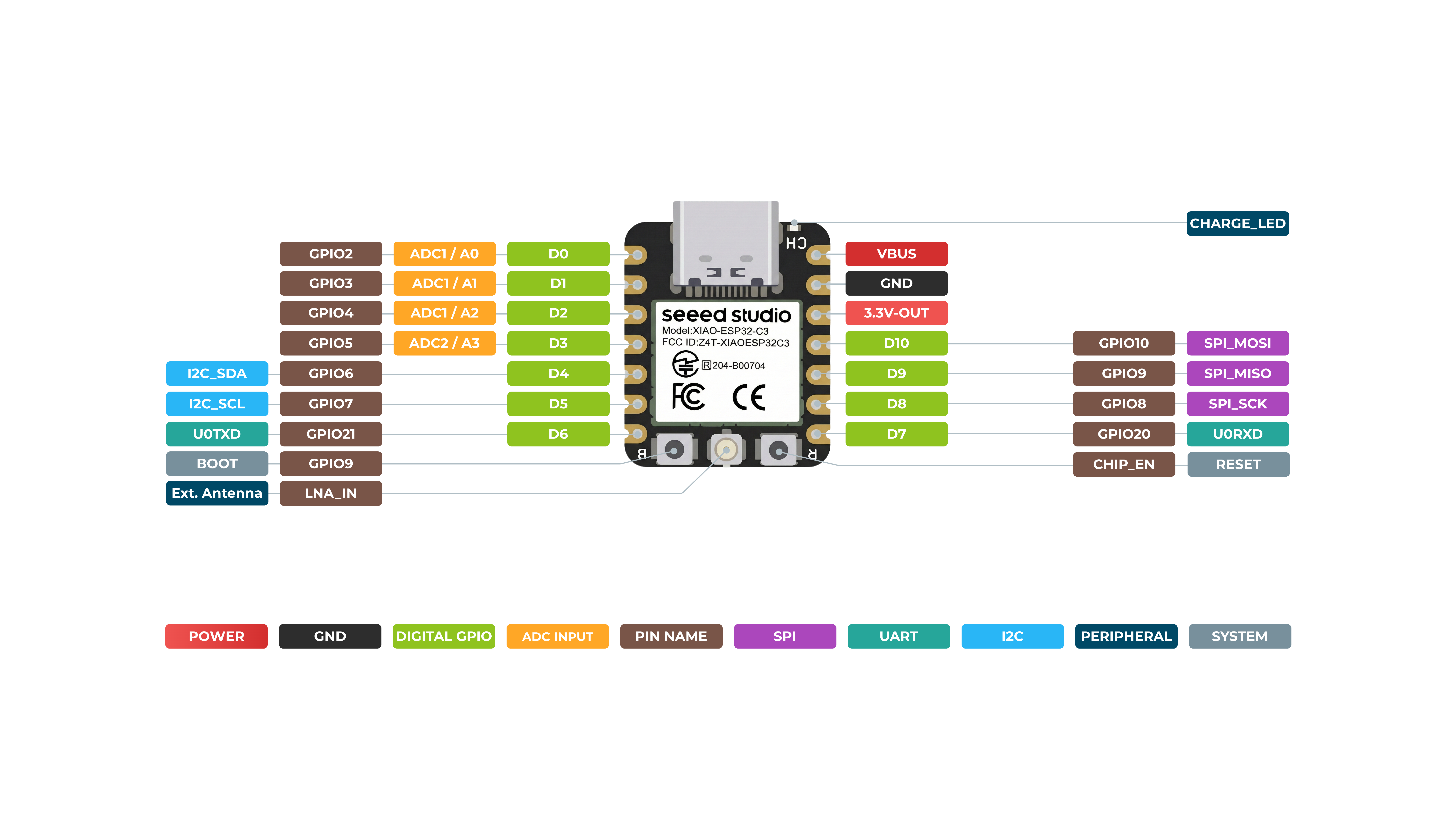
Multiplexación de pines
Seeed Studio XIAO ESP32C3 tiene interfaces muy completas. Hay 11 E/S digitales que se pueden usar como pines PWM y 4 entradas analógicas que se pueden usar como pines ADC. Es compatible con cuatro interfaces de comunicación serie como UART, I2C, SPI e I2S. ¡Este wiki será útil para aprender sobre estas interfaces e implementarlas en tus próximos proyectos!
Descripción general del hardware
*A3(GP105) - Usa ADC2, que puede dejar de funcionar debido a señales de muestreo falsas. Para lecturas analógicas fiables, utiliza ADC1(A0/A1/A2) en su lugar. Consulta la hoja de datos del ESP32-C3.
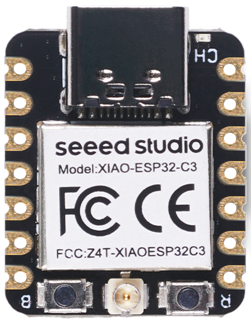
Parte frontal
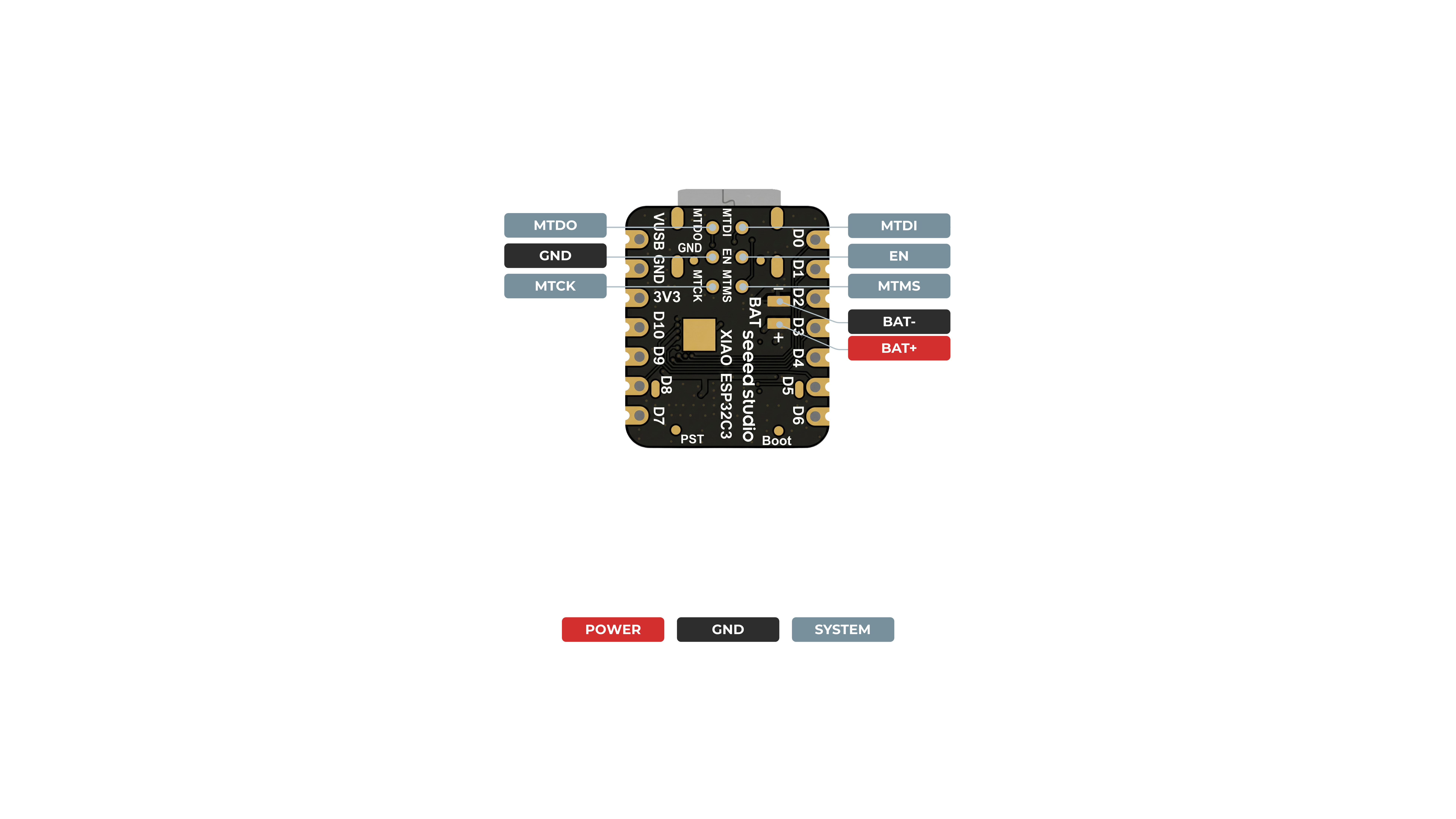
Parte trasera
Digital
Conecta un pulsador al pin D6 y un LED al pin D10. Luego sube el siguiente código para controlar el ENCENDIDO/APAGADO del LED usando el pulsador.
const int buttonPin = D6;     // pushbutton connected to digital pin 6
const int ledPin =  D10;      // LED connected to digital pin 10

int buttonState = 0;         // variable for reading the pushbutton status

void setup() {
  // initialize the LED pin as an output:
  pinMode(ledPin, OUTPUT);
  // initialize the pushbutton pin as an input:
  pinMode(buttonPin, INPUT);
}

void loop() {
  // read the state of the pushbutton value:
  buttonState = digitalRead(buttonPin);

  // check if the pushbutton is pressed. If it is, the buttonState is HIGH:
  if (buttonState == HIGH) {
    // turn LED on:
    digitalWrite(ledPin, HIGH);
  } else {
    // turn LED off:
    digitalWrite(ledPin, LOW);
  }
}
Digital como PWM
Conecta un LED al pin D10. Luego sube el siguiente código para ver cómo el LED se atenúa gradualmente.
int ledPin = D10;    // LED connected to digital pin 10

void setup() {
  // declaring LED pin as output
  pinMode(ledPin, OUTPUT);
}

void loop() {
  // fade in from min to max in increments of 5 points:
  for (int fadeValue = 0 ; fadeValue <= 255; fadeValue += 5) {
    // sets the value (range from 0 to 255):
    analogWrite(ledPin, fadeValue);
    // wait for 30 milliseconds to see the dimming effect
    delay(30);
  }

  // fade out from max to min in increments of 5 points:
  for (int fadeValue = 255 ; fadeValue >= 0; fadeValue -= 5) {
    // sets the value (range from 0 to 255):
    analogWrite(ledPin, fadeValue);
    // wait for 30 milliseconds to see the dimming effect
    delay(30);
  }
}
Analógico
Conecta un potenciómetro al pin A0 y un LED al pin D10. Luego sube el siguiente código para controlar el intervalo de parpadeo del LED girando la perilla del potenciómetro.
El rango de mapeo del ADC es 0-2500mV.
const int sensorPin = A0;
const int ledPin =  D10;

void setup() {
  pinMode(sensorPin, INPUT);  // declare the sensorPin as an INPUT
  pinMode(ledPin, OUTPUT);   // declare the ledPin as an OUTPUT
}

void loop() {
  // read the value from the sensor:
  int sensorValue = analogRead(sensorPin);
  // turn the ledPin on
  digitalWrite(ledPin, HIGH);
  // stop the program for <sensorValue> milliseconds:
  delay(sensorValue);
  // turn the ledPin off:
  digitalWrite(ledPin, LOW);
  // stop the program for for <sensorValue> milliseconds:
  delay(sensorValue);
}
Serie - UART
Método habitual: elige usar uno de los puertos serie USB o UART0
Hay 2 interfaces serie en esta placa:
- USB Serial
- UART0 Serial
No hay Serial2 para XIAO ESP32 C3.
Además, si necesitas usar Serial1, debes definir los pines; de lo contrario, puede que no reciba datos. Para la serie XIAO ESP32, usa Serial1 de la siguiente manera:
Serial1.begin(115200, SERIAL_8N1, D7, D6); // RX, TX
De forma predeterminada, el puerto serie USB está habilitado, lo que significa que puedes conectar la placa a un PC mediante USB Type-C y abrir el monitor serie en Arduino IDE para ver los datos enviados por serie.
Sin embargo, si quieres usar UART0 como puerto serie, necesitas conectar el pin D6 como pin TX y el pin D7 como pin RX con un adaptador USB-Serial.
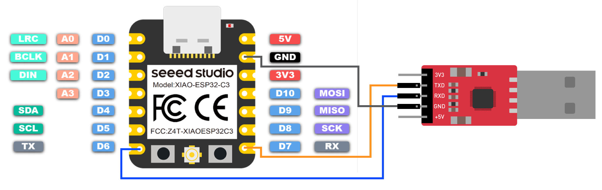
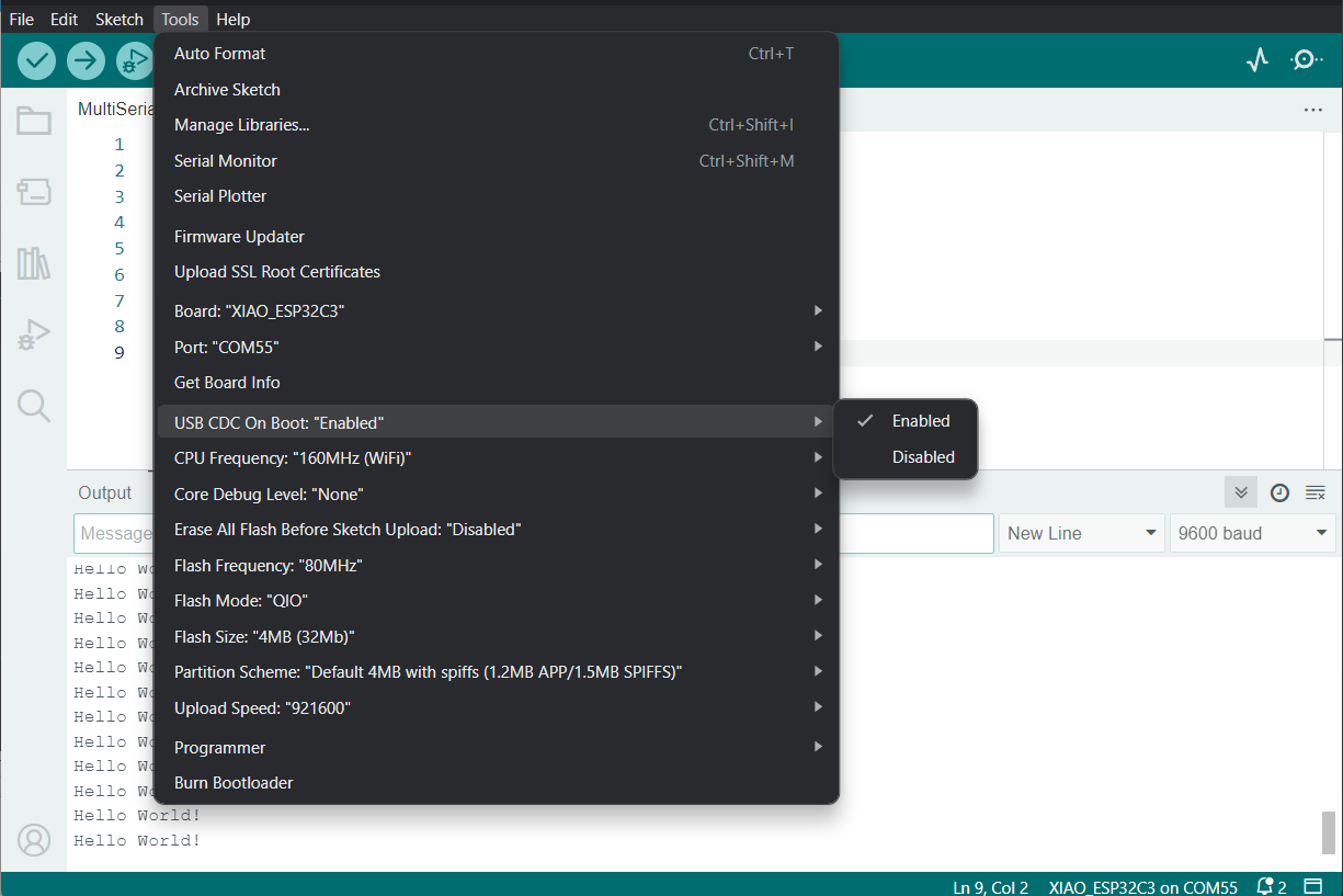
Además, necesitas configurar USB CDC On Boot como Disabled desde Arduino IDE.
NOTA: Cambia la foto cuando la placa aparezca en Arduino Board Manager
Sube el siguiente código a Arduino IDE para enviar la cadena "Hello World!" por serie
void setup() {
    Serial.begin(115200);
    while (!Serial);
}

void loop() {
    Serial.println("Hello World!");
    delay(1000);
}
La salida será la siguiente en el monitor serie de Arduino
Método especial: usar el puerto serie USB y UART0/UART1 al mismo tiempo
Muy a menudo, necesitamos usar sensores UART para conectarlos al puerto serie por hardware del XIAO ESP32C3 para obtener datos y, al mismo tiempo, puede que necesites usar el puerto serie USB para mostrar los datos en el monitor serie. Esto se puede lograr mediante algunos métodos especiales.
- Programa de ejemplo:
// Need this for the lower level access to set them up.
#include <HardwareSerial.h>

//Define two Serial devices mapped to the two internal UARTs
HardwareSerial MySerial0(0);
HardwareSerial MySerial1(1);

void setup()
{
    // For the USB, just use Serial as normal:
    Serial.begin(115200);

    // Configure MySerial0 on pins TX=D6 and RX=D7 (-1, -1 means use the default)
    MySerial0.begin(9600, SERIAL_8N1, -1, -1);
    MySerial0.print("MySerial0");

    // And configure MySerial1 on pins RX=D9, TX=D10
    MySerial1.begin(115200, SERIAL_8N1, 9, 10);
    MySerial1.print("MySerial1");
}

void loop()
{

}
Como puedes ver, el XIAO ESP32C3 en realidad tiene tres UART disponibles.
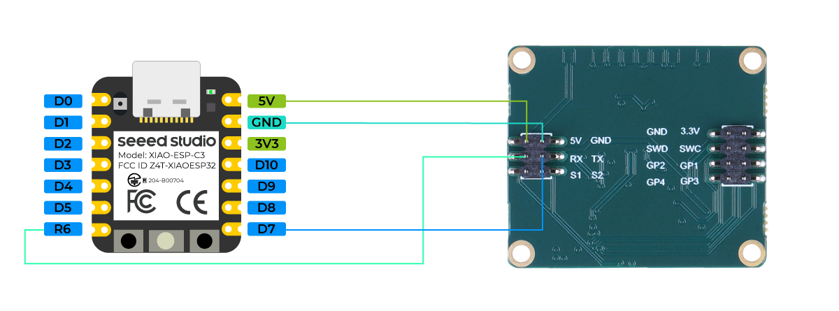
A continuación, tomaremos como ejemplo el 60GHz mmWave Sensor - Human Resting Breathing and Heartbeat Module, que está disponible para la venta, y explicaremos cómo usar los puertos serie por hardware D6 y D7 y el puerto serie USB.
Por favor, prepárate con lo siguiente.
| XIAO ESP32C3 | Sensor mmWave de 60GHz - Módulo de respiración en reposo y latidos del corazón humanos |
|---|---|
 | 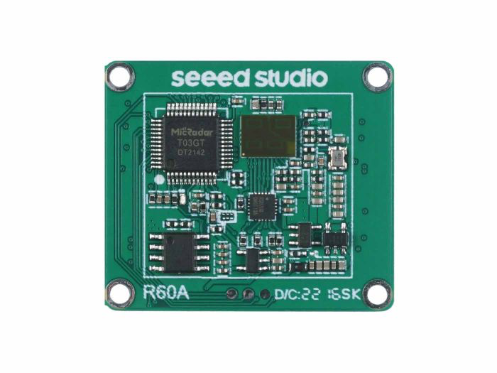 |
| Consigue uno ahora | Consigue uno ahora |
Descarga la biblioteca del sensor a tu ordenador y añádela al Arduino IDE.
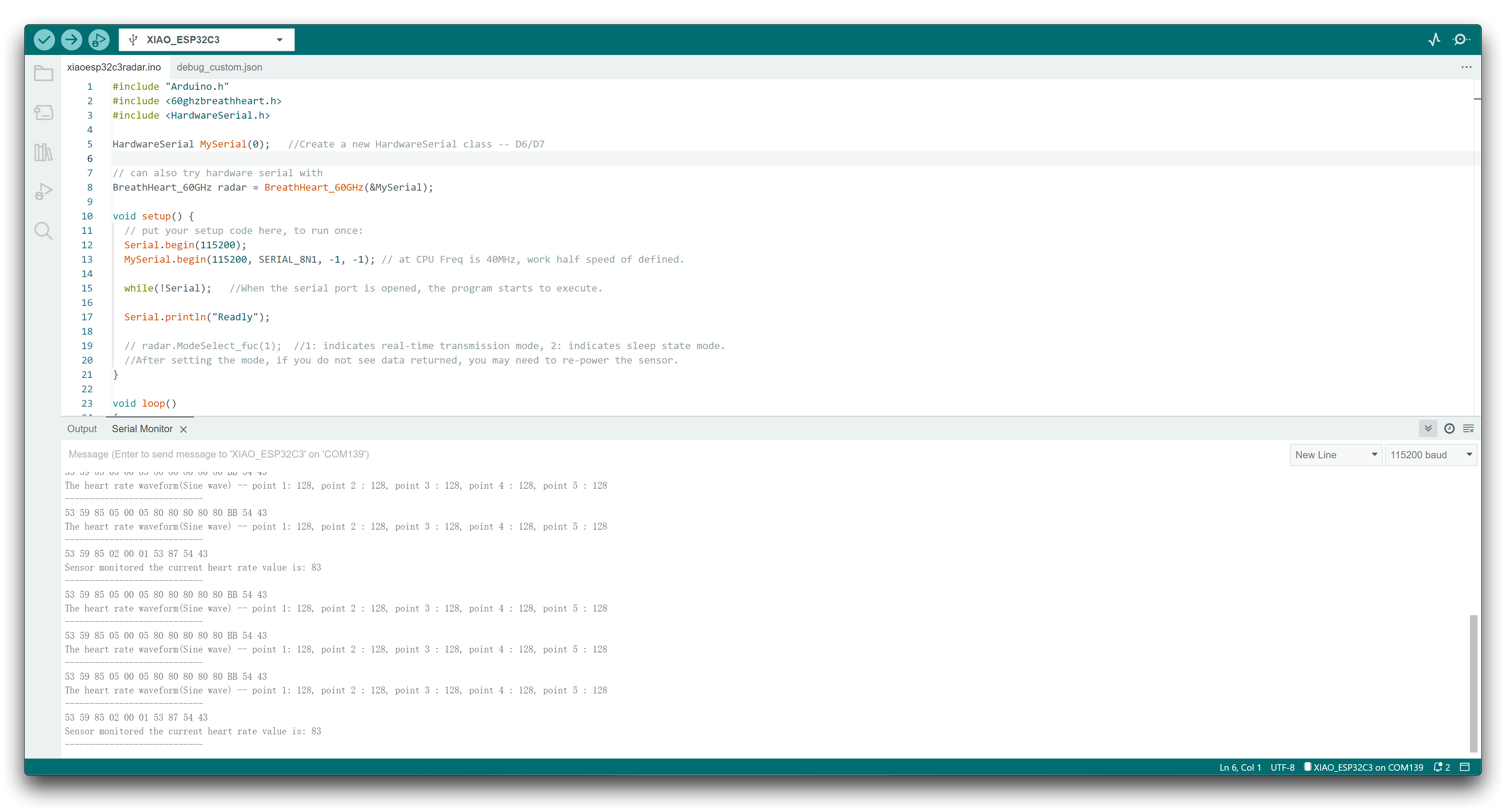
Aquí queremos analizar la información de los datos de latidos y respiración, luego puedes reescribir tu programa de esta manera.
#include "Arduino.h"
#include <60ghzbreathheart.h>
#include <HardwareSerial.h>

HardwareSerial MySerial(0);   //Create a new HardwareSerial class -- D6/D7

// can also try hardware serial with
BreathHeart_60GHz radar = BreathHeart_60GHz(&MySerial);

void setup() {
  // put your setup code here, to run once:
  Serial.begin(115200);
  MySerial.begin(115200, SERIAL_8N1, -1, -1); // at CPU Freq is 40MHz, work half speed of defined.

  while(!Serial);   //When the serial port is opened, the program starts to execute.

  Serial.println("Readly");

  // radar.ModeSelect_fuc(1);  //1: indicates real-time transmission mode, 2: indicates sleep state mode.
  //After setting the mode, if you do not see data returned, you may need to re-power the sensor.
}

void loop()
{
  // put your main code here, to run repeatedly:
  radar.Breath_Heart();           //Breath and heartbeat information output
  if(radar.sensor_report != 0x00){
    switch(radar.sensor_report){
      case HEARTRATEVAL:
        Serial.print("Sensor monitored the current heart rate value is: ");
        Serial.println(radar.heart_rate, DEC);
        Serial.println("----------------------------");
        break;
      case HEARTRATEWAVE:  //Valid only when real-time data transfer mode is on
        Serial.print("The heart rate waveform(Sine wave) -- point 1: ");
        Serial.print(radar.heart_point_1);
        Serial.print(", point 2 : ");
        Serial.print(radar.heart_point_2);
        Serial.print(", point 3 : ");
        Serial.print(radar.heart_point_3);
        Serial.print(", point 4 : ");
        Serial.print(radar.heart_point_4);
        Serial.print(", point 5 : ");
        Serial.println(radar.heart_point_5);
        Serial.println("----------------------------");
        break;
      case BREATHNOR:
        Serial.println("Sensor detects current breath rate is normal.");
        Serial.println("----------------------------");
        break;
      case BREATHRAPID:
        Serial.println("Sensor detects current breath rate is too fast.");
        Serial.println("----------------------------");
        break;
      case BREATHSLOW:
        Serial.println("Sensor detects current breath rate is too slow.");
        Serial.println("----------------------------");
        break;
      case BREATHNONE:
        Serial.println("There is no breathing information yet, please wait...");
        Serial.println("----------------------------");
        break;
      case BREATHVAL:
        Serial.print("Sensor monitored the current breath rate value is: ");
        Serial.println(radar.breath_rate, DEC);
        Serial.println("----------------------------");
        break;
      case BREATHWAVE:  //Valid only when real-time data transfer mode is on
        Serial.print("The breath rate waveform(Sine wave) -- point 1: ");
        Serial.print(radar.breath_point_1);
        Serial.print(", point 2 : ");
        Serial.print(radar.breath_point_2);
        Serial.print(", point 3 : ");
        Serial.print(radar.breath_point_3);
        Serial.print(", point 4 : ");
        Serial.print(radar.breath_point_4);
        Serial.print(", point 5 : ");
        Serial.println(radar.breath_point_5);
        Serial.println("----------------------------");
        break;
    }
  }
  delay(200);                       //Add time delay to avoid program jam
}
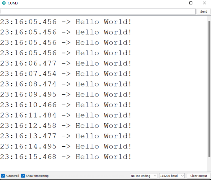
Por favor, sube el programa, luego abre el monitor serie y establece la velocidad en baudios a 115200.
A continuación, podemos conectar el sensor al XIAO ESP32C3 utilizando el siguiente método de conexión.
Si todo va bien, verás mensajes de datos en el monitor serie.
Uso de Serial1
De acuerdo con los diagramas de pines del XIAO ESP32C3 anteriores para parámetros específicos, podemos observar que hay un pin TX y un pin RX. Esto es diferente de la comunicación serie, pero el uso también es muy similar, excepto que es necesario añadir algunos parámetros. Así que a continuación, utilizaremos los pines sacados por el chip para la comunicación serie.
Función principal que se debe incluir:
Serial1.begin(BAUD,SERIAL_8N1,RX_PIN,TX_PIN);-- habilita Serial1, el prototipo de la función:<Serial.Type>.begin(unsigned long baud, uint32_t config, int8_t rxPin, int8_t txPin);baud:velocidad en baudiosconfig:bit de configuraciónrxPin:pin de recepcióntxPin:pin de envío
Cabe destacar que si utilizamos el puerto de pin digital para definir, este lugar debería ser #define RX_PIN D7、#define TX_PIN D6, por favor consulta los diagramas de pines de las diferentes XIAO Serie para parámetros específicos.
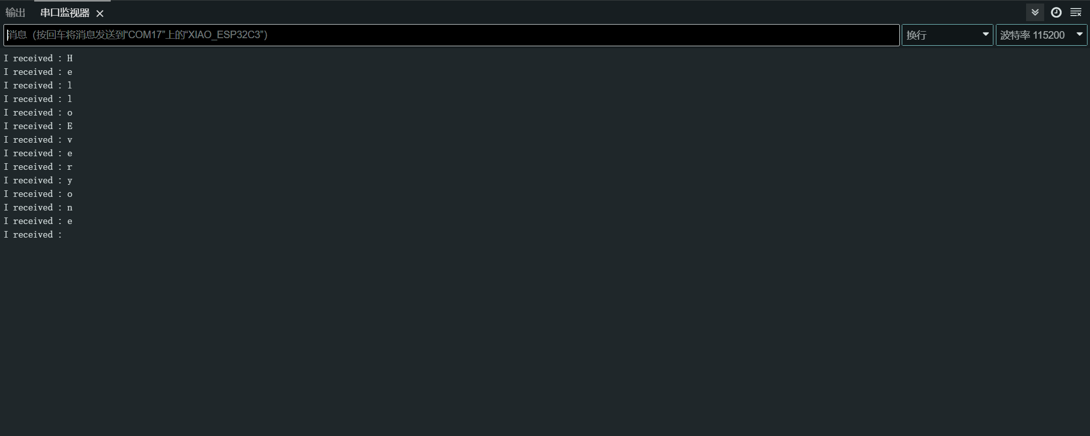
Aquí hay un programa de ejemplo:
#define RX_PIN D7
#define TX_PIN D6
#define BAUD 115200

void setup() {
    Serial1.begin(BAUD,SERIAL_8N1,RX_PIN,TX_PIN);
}

void loop() {
  if(Serial1.available() > 0)
  {
    char incominByte = Serial1.read();
    Serial1.print("I received : ");
    Serial1.println(incominByte);
  }
  delay(1000);
}
Después de subir el programa, abre el Monitor Serie en Arduino IDE y establece la velocidad en baudios a 115200. Entonces, puedes enviar el contenido que quieras al XIAO ESP32C3 a través del monitor serie Serial, y XIAO imprimirá cada byte del contenido que envíes. Aquí, el contenido que introduje es "Hello Everyone", mi gráfico de resultados es el siguiente
Software Serial
Para usar software serial, instala la biblioteca EspSoftwareSerial.
Actualmente recomendamos la versión 7.0.0 de la biblioteca EspSoftwareSerial. Otras versiones pueden tener distintos grados de problemas que impidan que el puerto serie por software funcione correctamente.
#include <SoftwareSerial.h>

SoftwareSerial mySerial(D7, D6); // RX, TX

void setup() {
  Serial.begin(9600);
  mySerial.begin(9600);
}

void loop() {
  if (mySerial.available()) {
    char data = mySerial.read();
    Serial.print("Received via software serial: ");
    Serial.println(data);
  }

  if (Serial.available()) {
    char data = Serial.read();
    mySerial.print("Received via hardware serial: ");
    mySerial.println(data);
  }
}
Este ejemplo configura un puerto serie por software en los pines D7 (RX) y D6 (TX) a 9600 baudios. Supervisa tanto el puerto serie por hardware (USB) como el puerto serie por software, reenviando los datos recibidos entre ellos.
I2C
Conexión de hardware
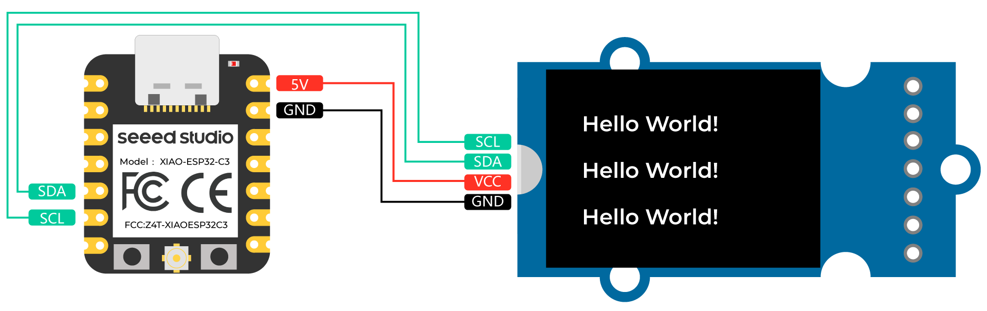
Conecta un Grove - OLED Yellow&Blue Display 0.96 (SSD1315) al XIAO ESP32C3 siguiendo la conexión de hardware que se muestra a continuación.
| Grove - OLED Yellow&Blue Display 0.96 (SSD1315) | XIAO ESP32C3 |
|---|---|
| SCL | SCL |
| SDA | SDA |
| VCC | 5V |
| GND | GND |
Configuración de software
-
Paso 1. Abre Arduino IDE, navega a
Sketch > Include Library > Manage Libraries... -
Paso 2. Busca u8g2 e instálalo

- Paso 3. Sube el siguiente código para mostrar cadenas de texto en la pantalla OLED
//#include <Arduino.h>
#include <U8g2lib.h>

#ifdef U8X8_HAVE_HW_SPI
#include <SPI.h>
#endif
#ifdef U8X8_HAVE_HW_I2C
#include <Wire.h>
#endif

U8G2_SSD1306_128X64_NONAME_F_SW_I2C u8g2(U8G2_R0, /* clock=*/ SCL, /* data=*/ SDA, /* reset=*/ U8X8_PIN_NONE);    //Low spped I2C

void setup(void) {
  u8g2.begin();
//  u8x8.setFlipMode(1);   // set number from 1 to 3, the screen word will rotary 180
}

void loop(void) {
  u8g2.clearBuffer();                   // clear the internal memory
  u8g2.setFont(u8g2_font_ncenB08_tr);   // choose a suitable font
  u8g2.drawStr(0,15,"Hello World!");    // write something to the internal memory
  u8g2.drawStr(0,30,"Hello World!");
  u8g2.drawStr(0,40,"Hello World!");
  u8g2.sendBuffer();                    // transfer internal memory to the display
//  delay(1000);
}
SPI
Conexión de hardware
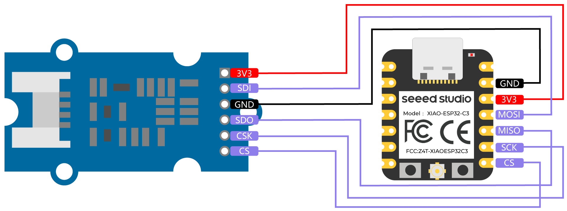
Conecta un Grove - High Precision Barometric Pressure Sensor (DPS310) al XIAO ESP32C3 siguiendo la conexión de hardware que se muestra a continuación.
| Grove - High Precision Barometric Pressure Sensor (DPS310) | XIAO ESP32C3 |
|---|---|
| 3V3 | 3V3 |
| SDI | MOSI |
| GND | GND |
| SDO | MISO |
| CSK | SCK |
| CS | CS |
Configuración de software
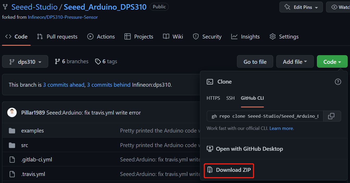
- Paso 1. Descarga Seeed_Arduino_DPS310 Library como un archivo zip
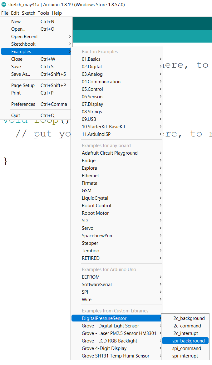
- Paso 2. Abre Arduino IDE, navega a
Sketch > Include Library > Add .ZIP Library...y abre el archivo zip descargado

- Paso 3. Navega a
File > Examples > DigitalPressureSensor > spi_backgroundpara abrir el ejemplo spi_background
Alternativamente, también puedes copiar el código de abajo
#include <Dps310.h>

// Dps310 Opject
Dps310 Dps310PressureSensor = Dps310();

void setup() {
    //pin number of your slave select line
    //XMC2GO
    int16_t pin_cs = SS;
    //for XMC 1100 Bootkit  & XMC4700 Relax Kit uncomment the following line
    //int16_t pin_cs = 10;

    Serial.begin(9600);
    while (!Serial);


    //Call begin to initialize Dps310
    //The parameter pin_nr is the number of the CS pin on your Microcontroller
    Dps310PressureSensor.begin(SPI, pin_cs);

    //temperature measure rate (value from 0 to 7)
    //2^temp_mr temperature measurement results per second
    int16_t temp_mr = 2;
    //temperature oversampling rate (value from 0 to 7)
    //2^temp_osr internal temperature measurements per result
    //A higher value increases precision
    int16_t temp_osr = 2;
    //pressure measure rate (value from 0 to 7)
    //2^prs_mr pressure measurement results per second
    int16_t prs_mr = 2;
    //pressure oversampling rate (value from 0 to 7)
    //2^prs_osr internal pressure measurements per result
    //A higher value increases precision
    int16_t prs_osr = 2;
    //startMeasureBothCont enables background mode
    //temperature and pressure ar measured automatically
    //High precision and hgh measure rates at the same time are not available.
    //Consult Datasheet (or trial and error) for more information
    int16_t ret = Dps310PressureSensor.startMeasureBothCont(temp_mr, temp_osr, prs_mr, prs_osr);
    //Use one of the commented lines below instead to measure only temperature or pressure
    //int16_t ret = Dps310PressureSensor.startMeasureTempCont(temp_mr, temp_osr);
    //int16_t ret = Dps310PressureSensor.startMeasurePressureCont(prs_mr, prs_osr);


    if (ret != 0) {
        Serial.print("Init FAILED! ret = ");
        Serial.println(ret);
    } else {
        Serial.println("Init complete!");
    }
}


void loop() {
    uint8_t pressureCount = 20;
    float pressure[pressureCount];
    uint8_t temperatureCount = 20;
    float temperature[temperatureCount];

    //This function writes the results of continuous measurements to the arrays given as parameters
    //The parameters temperatureCount and pressureCount should hold the sizes of the arrays temperature and pressure when the function is called
    //After the end of the function, temperatureCount and pressureCount hold the numbers of values written to the arrays
    //Note: The Dps310 cannot save more than 32 results. When its result buffer is full, it won't save any new measurement results
    int16_t ret = Dps310PressureSensor.getContResults(temperature, temperatureCount, pressure, pressureCount);

    if (ret != 0) {
        Serial.println();
        Serial.println();
        Serial.print("FAIL! ret = ");
        Serial.println(ret);
    } else {
        Serial.println();
        Serial.println();
        Serial.print(temperatureCount);
        Serial.println(" temperature values found: ");
        for (int16_t i = 0; i < temperatureCount; i++) {
            Serial.print(temperature[i]);
            Serial.println(" degrees of Celsius");
        }

        Serial.println();
        Serial.print(pressureCount);
        Serial.println(" pressure values found: ");
        for (int16_t i = 0; i < pressureCount; i++) {
            Serial.print(pressure[i]);
            Serial.println(" Pascal");
        }
    }

    //Wait some time, so that the Dps310 can refill its buffer
    delay(10000);
}
- Paso 4. Carga los códigos y abre el Monitor Serie
Nota: Una vez que cargues los códigos, no se ejecutarán automáticamente hasta que hagas clic en Serial Monitor en la esquina superior derecha de la ventana de Arduino.
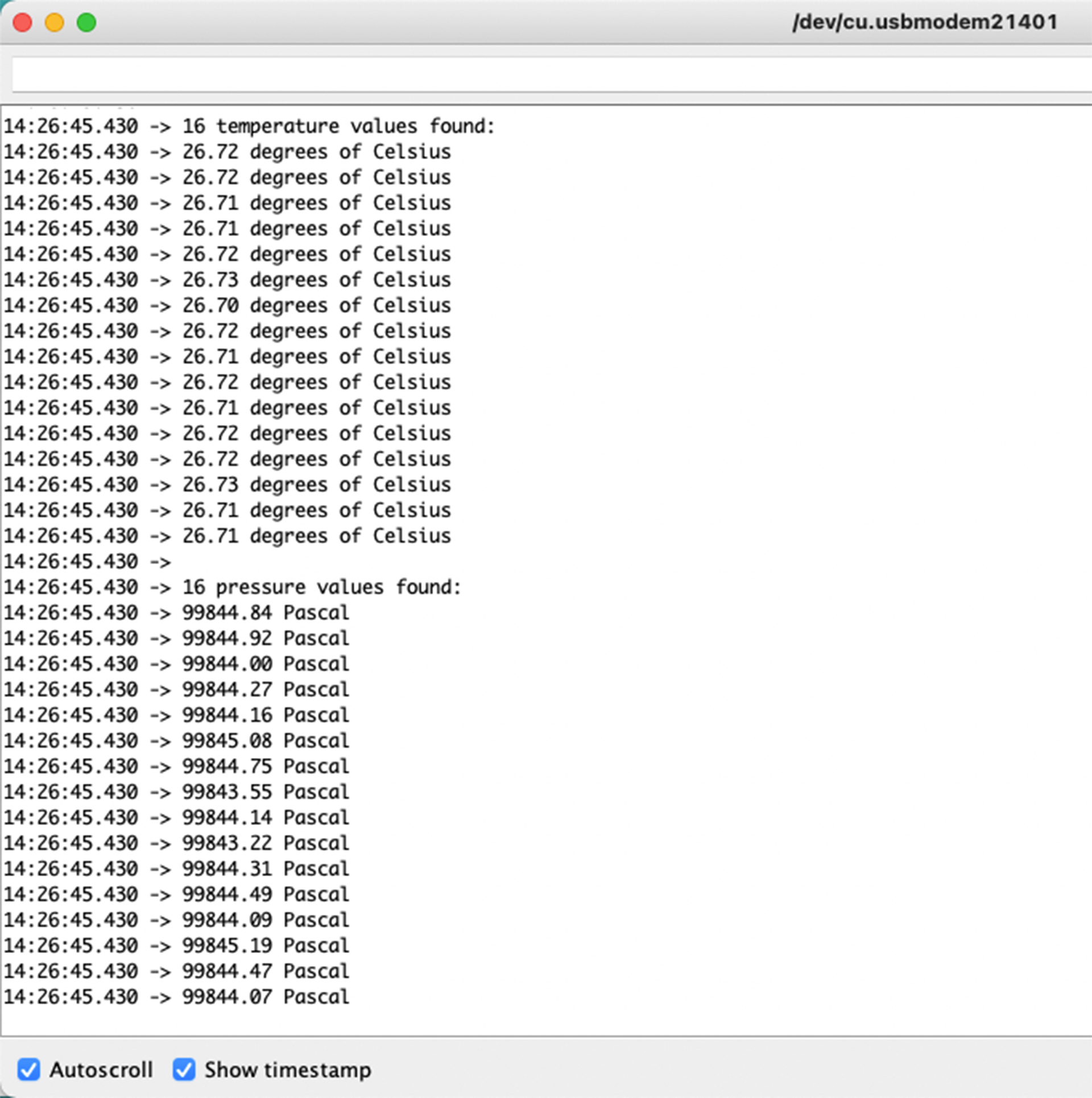
Ahora verás los datos de temperatura y presión mostrados uno tras otro en el monitor serie como arriba.
Nota sobre la asignación de E/S del XIAO ESP32C3
D9
El D9 del XIAO ESP32C3 se conecta al GPIO9 (15) del ESP32-C3, a la resistencia pull-up (R6) y al botón BOOT. El botón BOOT (y el botón RESET) te permite cambiar manualmente el modo de arranque del ESP32-C3.
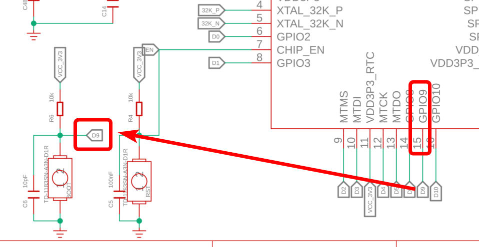
Al presionar el botón BOOT se conecta D9 a GND. Por lo tanto, es mejor usar D9 como una entrada de interruptor.
D6
D6 del XIAO ESP32C3 está conectado a U0TXD (28) del ESP32-C3. El estado de funcionamiento del bootloader de 1ª/2ª etapa se envía como texto a U0TXD.
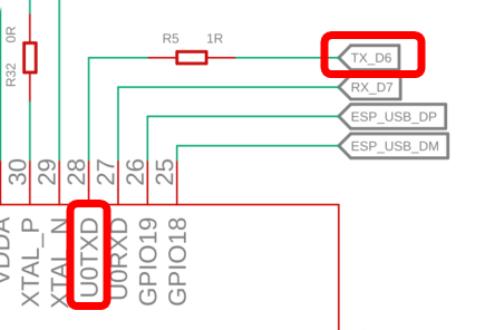
D6 se configura como salida UART al inicio, por lo que si usas D6 como entrada, podrías generar accidentalmente una corriente alta. Por lo tanto, se recomienda usar el pin D6 solo en modo de salida.
Sin embargo, dado que este D6 es una salida UART, debes tener cuidado con algunas cosas: una es que está en HIGH en modo de espera cuando no está comunicando. La otra es la salida de texto del bootloader de 1ª/2ª etapa. La señal oscila entre HIGH/LOW inmediatamente después del arranque y debe contrarrestarse si es necesario.
Así que intenta no usar D6. (Está bien usarlo después de que lo entiendas, por supuesto).
D8
D8 del Seeed Studio XIAO ESP32C3 está conectado al GPIO8 (14) del ESP32-C3.
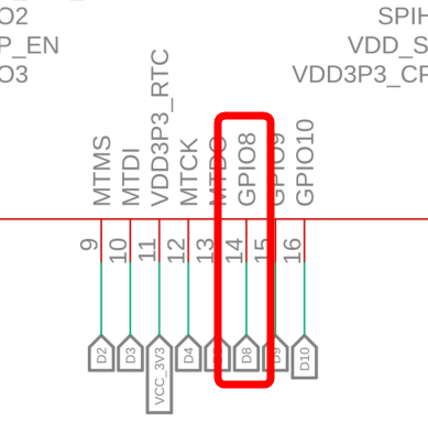
GPIO8 se referencia cuando el modo de arranque se establece en descarga de arranque manteniendo presionado el botón BOOT y debe estar en HIGH en ese momento. (Aquí dice: "The strapping combination of GPIO8 = 0 and GPIO9 = 0 is invalid and will trigger unexpected behaviour.")
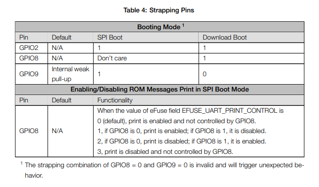
Si usas descarga de arranque, añade una resistencia pull-up para que GPIO8 esté en HIGH en el momento del arranque.
Un agradecimiento especial a nuestro colega de SeeedJP matsujirushi por probar y contribuir a esta sección. Aquí está el enlace de referencia al artículo original.