XIAO ESP32S3 Sense Modos de Suspensión
Aquí, presentaré algunos ejemplos simples para demostrar el uso de estos modos de suspensión de bajo consumo. Todas las placas ESP32 son versátiles, y la placa de desarrollo que estoy usando en este contexto es el XIAO ESP32S3 Sense.
Descripción del Hardware
| Seeed Studio XIAO ESP32S3 Sense |
|---|
 |
Sueño Profundo
Introducción
En el modo de Sueño Profundo, el ESP32 apaga las CPUs, la mayor parte de la RAM y todos los periféricos digitales sincronizados desde APB_CLK. Los únicos componentes que permanecen encendidos son:
- Controlador RTC
- Coprocesador ULP
- Memoria RTC FAST
- Memoria RTC SLOW
Métodos de Despertar
-
**Despertar por Temporizador:**El ESP32 puede despertar automáticamente después de un tiempo especificado configurando un temporizador.
-
**Despertar por Interrupción de Panel Táctil:**El dispositivo puede ser despertado por actividad en el panel táctil, adecuado para aplicaciones que requieren interacción del usuario.
-
**Despertar Externo:**El ESP32 puede ser despertado por señales externas (por ejemplo, pulsaciones de botones), ideal para aplicaciones de bajo consumo.
-
**Despertar por Actividad del Coprocesador ULP:**El coprocesador ULP puede operar independientemente, monitoreando condiciones específicas y despertando la CPU principal para ahorrar energía.
-
**Despertar por GPIO:**El dispositivo puede ser despertado por cambios en los estados de los pines GPIO (alto o bajo), proporcionando flexibilidad para varios sensores y periféricos.
A continuación se presentan tres ejemplos simples del XIAO ESP32 S3 Sense usando el modo DeepSleep.
Realización del código
- TimerWakeUP
- ExternalWakeUp
- TouchWakeUp
- SmoothBink_ULP
#define uS_TO_S_FACTOR 1000000ULL
#define TIME_TO_SLEEP  5

RTC_DATA_ATTR int bootCount = 0;

void print_wakeup_reason() {
  esp_sleep_wakeup_cause_t wakeup_reason;

  wakeup_reason = esp_sleep_get_wakeup_cause();

  switch (wakeup_reason) {
    case ESP_SLEEP_WAKEUP_EXT0:     Serial.println("Wakeup caused by external signal using RTC_IO"); break;
    case ESP_SLEEP_WAKEUP_EXT1:     Serial.println("Wakeup caused by external signal using RTC_CNTL"); break;
    case ESP_SLEEP_WAKEUP_TIMER:    Serial.println("Wakeup caused by timer"); break;
    case ESP_SLEEP_WAKEUP_TOUCHPAD: Serial.println("Wakeup caused by touchpad"); break;
    case ESP_SLEEP_WAKEUP_ULP:      Serial.println("Wakeup caused by ULP program"); break;
    default:                        Serial.printf("Wakeup was not caused by deep sleep: %d\n", wakeup_reason); break;
  }
}

void setup() {
  Serial.begin(115200);
  delay(1000);


  ++bootCount;
  Serial.println("Boot number: " + String(bootCount));


  print_wakeup_reason();


  esp_sleep_enable_timer_wakeup(TIME_TO_SLEEP * uS_TO_S_FACTOR);
  Serial.println("Setup ESP32 to sleep for every " + String(TIME_TO_SLEEP) + " Seconds");

  Serial.println("Going to sleep now");
  Serial.flush();
  esp_deep_sleep_start();
  Serial.println("This will never be printed");
}

void loop() {

}
Notas Detalladas
#define uS_TO_S_FACTOR 1000000ULL
- Define una macro para convertir microsegundos a segundos. 1000000ULL es el factor utilizado para convertir microsegundos a segundos.
#define TIME_TO_SLEEP 5
- Define una macro que establece el tiempo durante el cual el ESP32 entrará en modo de suspensión, en este caso, 5 segundos.
RTC_DATA_ATTR int bootCount = 0;
- Declara una variable entera
bootCountcon el atributoRTC_DATA_ATTR, que le permite retener su valor durante el sueño profundo.
void print_wakeup_reason() {
- Define una función llamada
print_wakeup_reason()que imprimirá la razón por la cual el ESP32 se despertó.
esp_sleep_wakeup_cause_t wakeup_reason;
- Declara una variable
wakeup_reasonde tipoesp_sleep_wakeup_cause_tpara almacenar la causa del evento de despertar.
wakeup_reason = esp_sleep_get_wakeup_cause();
- Llama a la función
esp_sleep_get_wakeup_cause()para obtener la razón del despertar y asígnala a la variablewakeup_reason.
  switch (wakeup_reason) {
    case ESP_SLEEP_WAKEUP_EXT0:     Serial.println("Wakeup caused by external signal using RTC_IO"); break;
    case ESP_SLEEP_WAKEUP_EXT1:     Serial.println("Wakeup caused by external signal using RTC_CNTL"); break;
    case ESP_SLEEP_WAKEUP_TIMER:    Serial.println("Wakeup caused by timer"); break;
    case ESP_SLEEP_WAKEUP_TOUCHPAD: Serial.println("Wakeup caused by touchpad"); break;
    case ESP_SLEEP_WAKEUP_ULP:      Serial.println("Wakeup caused by ULP program"); break;
    default:                        Serial.printf("Wakeup was not caused by deep sleep: %d\n", wakeup_reason); break;
}
ESP_SLEEP_WAKEUP_EXT0: Esta razón de despertar indica que el ESP32 se despertó debido a una señal externa detectada en un pin GPIO configurado para E/S RTC (Reloj de Tiempo Real). Esto se usa típicamente para despertar del sueño cuando se activa un botón o sensor.ESP_SLEEP_WAKEUP_EXT1: Esto indica que el despertar fue causado por una señal externa en pines GPIO gestionados por el controlador RTC. A diferencia de EXT0, EXT1 puede manejar múltiples pines y puede despertar cuando cualquiera de los pines especificados cambie de estado (por ejemplo, vaya a bajo o alto).ESP_SLEEP_WAKEUP_TIMER: Esta razón de despertar significa que el ESP32 se despertó después de una duración de temporizador predefinida. Esto es útil para aplicaciones que necesitan realizar tareas periódicas sin requerir interacción del usuario.ESP_SLEEP_WAKEUP_TOUCHPAD: Esto indica que el ESP32 se despertó debido a un evento de touchpad. Si un touchpad configurado para despertar detecta un toque, puede sacar al dispositivo del modo de sueño.ESP_SLEEP_WAKEUP_ULP: Esta razón de despertar significa que el despertar fue activado por un programa ULP (Ultra-Bajo Consumo). Los ULP pueden ejecutarse mientras la CPU principal está en sueño profundo y pueden despertar el ESP32 cuando se cumplen ciertas condiciones, permitiendo operación de bajo consumo con drenaje mínimo de batería.
++bootCount;
- Incrementar el contador de arranque e imprimirlo cada vez que el dispositivo se reinicie.
print_wakeup_reason();
- Imprime la razón del despertar del ESP32.
esp_sleep_enable_timer_wakeup(TIME_TO_SLEEP * uS_TO_S_FACTOR);
Serial.println("Setup ESP32 to sleep for every " + String(TIME_TO_SLEEP) + " Seconds");

Serial.println("Going to sleep now");
Serial.flush();
esp_deep_sleep_start();
Serial.println("This will never be printed");
esp_sleep_enable_timer_wakeup(TIME_TO_SLEEP * uS_TO_S_FACTOR);Habilita el temporizador para despertar el ESP32 después de un tiempo especificado.Serial.flush();Asegura que todos los datos serie se envíen antes de entrar en modo de suspensión.esp_deep_sleep_start();Pone el ESP32 en modo de suspensión profunda.
#include "driver/rtc_io.h"

#define BUTTON_PIN_BITMASK(GPIO) (1ULL << GPIO)
#define USE_EXT0_WAKEUP          1
#define WAKEUP_GPIO              GPIO_NUM_33
RTC_DATA_ATTR int bootCount = 0;


void print_wakeup_reason() {
  esp_sleep_wakeup_cause_t wakeup_reason;

  wakeup_reason = esp_sleep_get_wakeup_cause();

  switch (wakeup_reason) {
    case ESP_SLEEP_WAKEUP_EXT0:     Serial.println("Wakeup caused by external signal using RTC_IO"); break;
    case ESP_SLEEP_WAKEUP_EXT1:     Serial.println("Wakeup caused by external signal using RTC_CNTL"); break;
    case ESP_SLEEP_WAKEUP_TIMER:    Serial.println("Wakeup caused by timer"); break;
    case ESP_SLEEP_WAKEUP_TOUCHPAD: Serial.println("Wakeup caused by touchpad"); break;
    case ESP_SLEEP_WAKEUP_ULP:      Serial.println("Wakeup caused by ULP program"); break;
    default:                        Serial.printf("Wakeup was not caused by deep sleep: %d\n", wakeup_reason); break;
  }
}

void setup() {
  Serial.begin(115200);
  delay(1000);

  ++bootCount;
  Serial.println("Boot number: " + String(bootCount));

  print_wakeup_reason();

#if USE_EXT0_WAKEUP
  esp_sleep_enable_ext0_wakeup(WAKEUP_GPIO, 1);

  rtc_gpio_pullup_dis(WAKEUP_GPIO);
  rtc_gpio_pulldown_en(WAKEUP_GPIO);

#else
  esp_sleep_enable_ext1_wakeup_io(BUTTON_PIN_BITMASK(WAKEUP_GPIO), ESP_EXT1_WAKEUP_ANY_HIGH);

  rtc_gpio_pulldown_en(WAKEUP_GPIO);
  rtc_gpio_pullup_dis(WAKEUP_GPIO);
#endif

  Serial.println("Going to sleep now");
  esp_deep_sleep_start();
  Serial.println("This will never be printed");
}

void loop() {
}
Notas Detalladas
#include "driver/rtc_io.h"
- Incluye el controlador de E/S RTC para acceder a GPIO RTC.
#define BUTTON_PIN_BITMASK(GPIO) (1ULL << GPIO)
#define USE_EXT0_WAKEUP          1
#define WAKEUP_GPIO              GPIO_NUM_33
RTC_DATA_ATTR int bootCount = 0;
- 2 ^ GPIO_NUMBER en hexadecimal
- 1 = despertar EXT0, 0 = despertar EXT1
- Solo se permiten RTC IO - ejemplo de Pin ESP32
  switch (wakeup_reason) {
    case ESP_SLEEP_WAKEUP_EXT0:     Serial.println("Wakeup caused by external signal using RTC_IO"); break;
    case ESP_SLEEP_WAKEUP_EXT1:     Serial.println("Wakeup caused by external signal using RTC_CNTL"); break;
    case ESP_SLEEP_WAKEUP_TIMER:    Serial.println("Wakeup caused by timer"); break;
    case ESP_SLEEP_WAKEUP_TOUCHPAD: Serial.println("Wakeup caused by touchpad"); break;
    case ESP_SLEEP_WAKEUP_ULP:      Serial.println("Wakeup caused by ULP program"); break;
    default:                        Serial.printf("Wakeup was not caused by deep sleep: %d\n", wakeup_reason); break;
}
ESP_SLEEP_WAKEUP_EXT0: Esta razón de despertar indica que el ESP32 se despertó debido a una señal externa detectada en un pin GPIO configurado para E/S RTC (Reloj de Tiempo Real). Esto se usa típicamente para despertar del sueño cuando se activa un botón o sensor.ESP_SLEEP_WAKEUP_EXT1: Esto indica que el despertar fue causado por una señal externa en pines GPIO gestionados por el controlador RTC. A diferencia de EXT0, EXT1 puede manejar múltiples pines y puede despertar cuando cualquiera de los pines especificados cambie de estado (por ejemplo, vaya a bajo o alto).ESP_SLEEP_WAKEUP_TIMER: Esta razón de despertar significa que el ESP32 se despertó después de una duración de temporizador predefinida. Esto es útil para aplicaciones que necesitan realizar tareas periódicas sin requerir interacción del usuario.ESP_SLEEP_WAKEUP_TOUCHPAD: Esto indica que el ESP32 se despertó debido a un evento de touchpad. Si un touchpad configurado para despertar detecta un toque, puede sacar al dispositivo del modo de sueño.ESP_SLEEP_WAKEUP_ULP: Esta razón de despertar significa que el despertar fue activado por un programa ULP (Ultra-Bajo Consumo). Los ULP pueden ejecutarse mientras la CPU principal está en sueño profundo y pueden despertar el ESP32 cuando se cumplen ciertas condiciones, permitiendo operación de bajo consumo con drenaje mínimo de batería.
  Serial.begin(115200);
  delay(1000);
  ++bootCount;
  Serial.println("Boot number: " + String(bootCount));
  print_wakeup_reason();
++bootCount;Incrementa el número de arranque y lo imprime en cada reinicioprint_wakeup_reason();Imprime la razón de activación para ESP32
#if USE_EXT0_WAKEUP
  esp_sleep_enable_ext0_wakeup(WAKEUP_GPIO, 1);

  rtc_gpio_pullup_dis(WAKEUP_GPIO);
  rtc_gpio_pulldown_en(WAKEUP_GPIO);
esp_sleep_enable_ext0_wakeup(WAKEUP_GPIO, 1);Habilita el despertar EXT0 en el pin GPIO especificado cuando se pone en alto.rtc_gpio_pullup_dis(WAKEUP_GPIO);Deshabilita la resistencia pull-up en el pin GPIO de despertar.rtc_gpio_pulldown_en(WAKEUP_GPIO);Habilita la resistencia pull-down en el pin GPIO de despertar.
#else
  esp_sleep_enable_ext1_wakeup_io(BUTTON_PIN_BITMASK(WAKEUP_GPIO), ESP_EXT1_WAKEUP_ANY_HIGH);

  rtc_gpio_pulldown_en(WAKEUP_GPIO);
  rtc_gpio_pullup_dis(WAKEUP_GPIO);
-
esp_sleep_enable_ext1_wakeup_io(BUTTON_PIN_BITMASK(WAKEUP_GPIO), ESP_EXT1_WAKEUP_ANY_HIGH);EXT1 WAKEUP -
rtc_gpio_pulldown_en(WAKEUP_GPIO);GPIO33 está conectado a GND para despertar en HIGH -
rtc_gpio_pullup_dis(WAKEUP_GPIO);Deshabilitar PULL_UP para permitir que despierte en HIGH -
esp_sleep_enable_ext1_wakeup_io(BUTTON_PIN_BITMASK(WAKEUP_GPIO), ESP_EXT1_WAKEUP_ANY_HIGH);Si fueras a usar ext1, lo usarías así -
rtc_gpio_pulldown_en(WAKEUP_GPIO);GPIO33 está conectado a GND para despertar en HIGH -
rtc_gpio_pullup_dis(WAKEUP_GPIO);Deshabilitar PULL_UP para permitir que despierte en HIGH
  Serial.println("Going to sleep now");
  esp_deep_sleep_start();
  Serial.println("This will never be printed");
esp_deep_sleep_start();Pone el ESP32 en modo de sueño profundo.
#if CONFIG_IDF_TARGET_ESP32
#define THRESHOLD 40
#elif (CONFIG_IDF_TARGET_ESP32S2 || CONFIG_IDF_TARGET_ESP32S3)
#define THRESHOLD 5000
#else
#define THRESHOLD 500
#endif

RTC_DATA_ATTR int bootCount = 0;
touch_pad_t touchPin;

void print_wakeup_reason() {
  esp_sleep_wakeup_cause_t wakeup_reason;

  wakeup_reason = esp_sleep_get_wakeup_cause();

  switch (wakeup_reason) {
    case ESP_SLEEP_WAKEUP_EXT0:     Serial.println("Wakeup caused by external signal using RTC_IO"); break;
    case ESP_SLEEP_WAKEUP_EXT1:     Serial.println("Wakeup caused by external signal using RTC_CNTL"); break;
    case ESP_SLEEP_WAKEUP_TIMER:    Serial.println("Wakeup caused by timer"); break;
    case ESP_SLEEP_WAKEUP_TOUCHPAD: Serial.println("Wakeup caused by touchpad"); break;
    case ESP_SLEEP_WAKEUP_ULP:      Serial.println("Wakeup caused by ULP program"); break;
    default:                        Serial.printf("Wakeup was not caused by deep sleep: %d\n", wakeup_reason); break;
  }
}

void print_wakeup_touchpad() {
  touchPin = esp_sleep_get_touchpad_wakeup_status();

#if CONFIG_IDF_TARGET_ESP32
  switch (touchPin) {
    case 0:  Serial.println("Touch detected on GPIO 4"); break;
    case 1:  Serial.println("Touch detected on GPIO 0"); break;
    case 2:  Serial.println("Touch detected on GPIO 2"); break;
    case 3:  Serial.println("Touch detected on GPIO 15"); break;
    case 4:  Serial.println("Touch detected on GPIO 13"); break;
    case 5:  Serial.println("Touch detected on GPIO 12"); break;
    case 6:  Serial.println("Touch detected on GPIO 14"); break;
    case 7:  Serial.println("Touch detected on GPIO 27"); break;
    case 8:  Serial.println("Touch detected on GPIO 33"); break;
    case 9:  Serial.println("Touch detected on GPIO 32"); break;
    default: Serial.println("Wakeup not by touchpad"); break;
  }
#else
  if (touchPin < TOUCH_PAD_MAX) {
    Serial.printf("Touch detected on GPIO %d\n", touchPin);
  } else {
    Serial.println("Wakeup not by touchpad");
  }
#endif
}

void setup() {
  Serial.begin(115200);
  delay(1000);

  ++bootCount;
  Serial.println("Boot number: " + String(bootCount));

  print_wakeup_reason();
  print_wakeup_touchpad();

#if CONFIG_IDF_TARGET_ESP32

  touchSleepWakeUpEnable(T3, THRESHOLD);
  touchSleepWakeUpEnable(T7, THRESHOLD);

#else
  touchSleepWakeUpEnable(T3, THRESHOLD);

#endif

  Serial.println("Going to sleep now");
  esp_deep_sleep_start();
  Serial.println("This will never be printed");
}

void loop() {

}
Notas Detalladas
#if CONFIG_IDF_TARGET_ESP32
#define THRESHOLD 40
#elif (CONFIG_IDF_TARGET_ESP32S2 || CONFIG_IDF_TARGET_ESP32S3)
#define THRESHOLD 5000
#else
#define THRESHOLD 500
#endif
- Verificar si el objetivo es ESP32
- Definir el umbral para la sensibilidad táctil para ESP32
- Verificar si el objetivo es ESP32S2 o ESP32S3
- Definir un umbral más alto para la sensibilidad táctil para ESP32S2/S3
- Si el objetivo no es ninguno de los anteriores
- Definir un umbral predeterminado para otros objetivos
RTC_DATA_ATTR int bootCount = 0; // Declare a variable to count boots, stored in RTC memory.
touch_pad_t touchPin; // Declare a variable to hold the touchpad pin status.

void print_wakeup_reason() { // Function to print the reason for waking up.
  esp_sleep_wakeup_cause_t wakeup_reason; // Variable to hold the wakeup reason.

  wakeup_reason = esp_sleep_get_wakeup_cause(); // Get the cause of the wakeup.
RTC_DATA_ATTR int bootCount = 0;Declara una variable para contar los arranques, almacenada en la memoria RTC.touch_pad_t touchPin;Declara una variable para mantener el estado del pin del touchpad.void print_wakeup_reason()Función para imprimir la razón del despertar.esp_sleep_wakeup_cause_t wakeup_reason;Variable para mantener la razón del despertar.wakeup_reason = esp_sleep_get_wakeup_cause();Obtiene la causa del despertar.
  switch (wakeup_reason) {
    case ESP_SLEEP_WAKEUP_EXT0:     Serial.println("Wakeup caused by external signal using RTC_IO"); break;
    case ESP_SLEEP_WAKEUP_EXT1:     Serial.println("Wakeup caused by external signal using RTC_CNTL"); break;
    case ESP_SLEEP_WAKEUP_TIMER:    Serial.println("Wakeup caused by timer"); break;
    case ESP_SLEEP_WAKEUP_TOUCHPAD: Serial.println("Wakeup caused by touchpad"); break;
    case ESP_SLEEP_WAKEUP_ULP:      Serial.println("Wakeup caused by ULP program"); break;
    default:                        Serial.printf("Wakeup was not caused by deep sleep: %d\n", wakeup_reason); break;
}
ESP_SLEEP_WAKEUP_EXT0: Esta razón de despertar indica que el ESP32 se despertó debido a una señal externa detectada en un pin GPIO configurado para E/S RTC (Reloj de Tiempo Real). Esto se usa típicamente para despertar del sueño cuando se activa un botón o sensor.ESP_SLEEP_WAKEUP_EXT1: Esto indica que el despertar fue causado por una señal externa en pines GPIO gestionados por el controlador RTC. A diferencia de EXT0, EXT1 puede manejar múltiples pines y puede despertar cuando cualquiera de los pines especificados cambie de estado (por ejemplo, vaya a bajo o alto).ESP_SLEEP_WAKEUP_TIMER: Esta razón de despertar significa que el ESP32 se despertó después de una duración de temporizador predefinida. Esto es útil para aplicaciones que necesitan realizar tareas periódicas sin requerir interacción del usuario.ESP_SLEEP_WAKEUP_TOUCHPAD: Esto indica que el ESP32 se despertó debido a un evento de touchpad. Si un touchpad configurado para despertar detecta un toque, puede sacar al dispositivo del modo de sueño.ESP_SLEEP_WAKEUP_ULP: Esta razón de despertar significa que el despertar fue activado por un programa ULP (Ultra-Bajo Consumo). Los ULP pueden ejecutarse mientras la CPU principal está en sueño profundo y pueden despertar el ESP32 cuando se cumplen ciertas condiciones, permitiendo operación de bajo consumo con drenaje mínimo de batería.
void print_wakeup_touchpad() {
  touchPin = esp_sleep_get_touchpad_wakeup_status();

#if CONFIG_IDF_TARGET_ESP32
  switch (touchPin) {
    case 0:  Serial.println("Touch detected on GPIO 4"); break;
    case 1:  Serial.println("Touch detected on GPIO 0"); break;
    case 2:  Serial.println("Touch detected on GPIO 2"); break;
    case 3:  Serial.println("Touch detected on GPIO 15"); break;
    case 4:  Serial.println("Touch detected on GPIO 13"); break;
    case 5:  Serial.println("Touch detected on GPIO 12"); break;
    case 6:  Serial.println("Touch detected on GPIO 14"); break;
    case 7:  Serial.println("Touch detected on GPIO 27"); break;
    case 8:  Serial.println("Touch detected on GPIO 33"); break;
    case 9:  Serial.println("Touch detected on GPIO 32"); break;
    default: Serial.println("Wakeup not by touchpad"); break;
  }
#else
  if (touchPin < TOUCH_PAD_MAX) {
    Serial.printf("Touch detected on GPIO %d\n", touchPin);
  } else {
    Serial.println("Wakeup not by touchpad");
  }
#endif
}
case 0:Toque detectado en GPIO 4.case 1:Toque detectado en GPIO 0.case 2:Toque detectado en GPIO 2.case 3:Toque detectado en GPIO 15.case 4:Toque detectado en GPIO 13.case 5:Toque detectado en GPIO 12.case 6:Toque detectado en GPIO 14.case 7:Toque detectado en GPIO 27.case 8:Toque detectado en GPIO 33.case 9:Toque detectado en GPIO 32.default:Caso por defecto si no se detecta toque.
void setup() {
  Serial.begin(115200);
  delay(1000);

  ++bootCount;
  Serial.println("Boot number: " + String(bootCount));

  print_wakeup_reason();
  print_wakeup_touchpad();

#if CONFIG_IDF_TARGET_ESP32

  touchSleepWakeUpEnable(T3, THRESHOLD);
  touchSleepWakeUpEnable(T7, THRESHOLD);

#else
  touchSleepWakeUpEnable(T3, THRESHOLD);

#endif

  Serial.println("Going to sleep now");
  esp_deep_sleep_start();
  Serial.println("This will never be printed");
}
-
++bootCount;Incrementar el contador de arranque. -
print_wakeup_reason();Imprimir la razón del despertar. -
print_wakeup_touchpad();Imprimir el estado de despertar del touchpad. -
#if CONFIG_IDF_TARGET_ESP32Verificar si el objetivo es ESP32 -
touchSleepWakeUpEnable(T3, THRESHOLD);Habilitar despertar táctil para T3 con el umbral definido. -
touchSleepWakeUpEnable(T7, THRESHOLD);Habilitar despertar táctil para T7 con el umbral definido. -
touchSleepWakeUpEnable(T3, THRESHOLD);Habilitar despertar táctil para T3 con el umbral definido. -
esp_deep_sleep_start();Poner el ESP32 en modo de sueño profundo.
#include <Arduino.h> // Include the Arduino core library
#include "esp32/ulp.h" // Include ESP32 ULP-related library
#include "driver/rtc_io.h" // Include RTC GPIO driver library
#include "soc/rtc_io_reg.h" // Include RTC IO register definitions

#define RTC_dutyMeter 0 // Define the storage location for dutyMeter
#define RTC_dir       4 // Define the storage location for direction
#define RTC_fadeDelay 12 // Define the storage location for fadeDelay

uint32_t *fadeCycleDelay = &RTC_SLOW_MEM[RTC_fadeDelay]; // Point to the fadeDelay location in RTC_SLOW_MEM
#define ULP_START_OFFSET 32 // Define the starting offset for the ULP program

RTC_DATA_ATTR uint32_t ULP_Started = 0; // Variable to indicate if the ULP program has started
// Time-to-Sleep
#define uS_TO_S_FACTOR 1000000ULL // Conversion factor from microseconds to seconds
#define TIME_TO_SLEEP  5 // Time to enter deep sleep (in seconds)

void ulp_setup() { // ULP setup function
  if (ULP_Started) { // If ULP has already started, return
    return;
  }
  *fadeCycleDelay = 5; // Initialize fadeCycleDelay to 5
  ULP_Started = 1; // Mark ULP as started

  const gpio_num_t MeterPWMPin = GPIO_NUM_2; // Define the PWM pin
  rtc_gpio_init(MeterPWMPin); // Initialize GPIO
  rtc_gpio_set_direction(MeterPWMPin, RTC_GPIO_MODE_OUTPUT_ONLY); // Set the pin as output
  rtc_gpio_set_level(MeterPWMPin, 0); // Set the initial pin level to low

  const uint32_t MeterPWMBit = rtc_io_number_get(MeterPWMPin) + RTC_GPIO_OUT_DATA_S; // Get the bit for the PWM pin

  enum labels { // Define labels for the ULP program
    INIFINITE_LOOP,
    RUN_PWM,
    NEXT_PWM_CYCLE,
    PWM_ON,
    PWM_OFF,
    END_PWM_CYCLE,
    POSITIVE_DIR,
    DEC_DUTY,
    INC_DUTY,
  };

  // Define the ULP program
  const ulp_insn_t ulp_prog[] = {
    // Initial value setup
    I_MOVI(R0, 0), // Move 0 to register R0
    I_ST(R0, R0, RTC_dutyMeter), // Store the value of R0 in dutyMeter
    I_MOVI(R1, 1), // Move 1 to register R1
    I_ST(R1, R0, RTC_dir), // Store the value of R1 in dir

    M_LABEL(INIFINITE_LOOP), // Define the infinite loop label

    I_MOVI(R3, 0), // Move 0 to R3
    I_LD(R3, R3, RTC_fadeDelay), // Load the value from fadeDelay into R3
    M_LABEL(RUN_PWM), // Define the run PWM label

    I_MOVI(R0, 0), // Move 0 to R0
    I_LD(R0, R0, RTC_dutyMeter), // Load the value from dutyMeter into R0
    M_BL(NEXT_PWM_CYCLE, 1), // Branch to the next PWM cycle
    I_WR_REG(RTC_GPIO_OUT_W1TS_REG, MeterPWMBit, MeterPWMBit, 1), // Set the PWM pin high
    M_LABEL(PWM_ON), // Define the PWM ON label
    M_BL(NEXT_PWM_CYCLE, 1), // Branch to the next PWM cycle
    // I_DELAY(8), // Commented out delay instruction
    I_SUBI(R0, R0, 1), // Decrement R0 by 1
    M_BX(PWM_ON), // Go back to the PWM ON label

    M_LABEL(NEXT_PWM_CYCLE), // Define the next PWM cycle label
    I_MOVI(R0, 0), // Move 0 to R0
    I_LD(R0, R0, RTC_dutyMeter), // Load the value from dutyMeter into R0
    I_MOVI(R1, 100), // Move 100 to R1
    I_SUBR(R0, R1, R0), // R0 = R1 - R0
    M_BL(END_PWM_CYCLE, 1), // Branch to the end PWM cycle label
    I_WR_REG(RTC_GPIO_OUT_W1TC_REG, MeterPWMBit, MeterPWMBit, 1), // Set the PWM pin low
    M_LABEL(PWM_OFF), // Define the PWM OFF label
    M_BL(END_PWM_CYCLE, 1), // Branch to the end PWM cycle label
    // I_DELAY(8), // Commented out delay instruction
    I_SUBI(R0, R0, 1), // Decrement R0 by 1
    M_BX(PWM_OFF), // Go back to the PWM OFF label
    M_LABEL(END_PWM_CYCLE), // Define the end PWM cycle label

    I_SUBI(R3, R3, 1), // Decrement R3 by 1
    I_MOVR(R0, R3), // Move R3 to R0
    M_BGE(RUN_PWM, 1), // If R3 >= 0, branch to RUN_PWM

    I_MOVI(R1, 0), // Move 0 to R1
    I_LD(R1, R1, RTC_dutyMeter), // Load the value from dutyMeter into R1
    I_MOVI(R0, 0), // Move 0 to R0
    I_LD(R0, R0, RTC_dir), // Load the value from dir into R0

    M_BGE(POSITIVE_DIR, 1), // If R0 >= 0, branch to POSITIVE_DIR

    I_MOVR(R0, R1), // Move R1 to R0
    M_BGE(DEC_DUTY, 1), // If R1 >= 0, branch to DEC_DUTY
    I_MOVI(R3, 0), // Move 0 to R3
    I_MOVI(R2, 1), // Move 1 to R2
    I_ST(R2, R3, RTC_dir), // Store the value of R2 in dir
    M_BX(INC_DUTY), // Branch to INC_DUTY label
    M_LABEL(DEC_DUTY), // Define DEC_DUTY label
    I_SUBI(R0, R0, 2), // Decrement R0 by 2
    I_MOVI(R2, 0), // Move 0 to R2
    I_ST(R0, R2, RTC_dutyMeter), // Store the value of R0 in dutyMeter
    M_BX(INIFINITE_LOOP), // Go back to the infinite loop label

    M_LABEL(POSITIVE_DIR), // Define POSITIVE_DIR label

    I_MOVR(R0, R1), // Move R1 to R0
    M_BL(INC_DUTY, 100), // Branch to INC_DUTY label with parameter 100
    I_MOVI(R2, 0), // Move 0 to R2
    I_ST(R2, R2, RTC_dir), // Store the value of R2 in dir
    M_BX(DEC_DUTY), // Branch to DEC_DUTY label
    M_LABEL(INC_DUTY), // Define INC_DUTY label
    I_ADDI(R0, R0, 2), // Increment R0 by 2
    I_MOVI(R2, 0), // Move 0 to R2
    I_ST(R0, R2, RTC_dutyMeter), // Store the value of R0 in dutyMeter

    M_BX(INIFINITE_LOOP), // Go back to the infinite loop label
  };
  // Run the ULP program
  size_t size = sizeof(ulp_prog) / sizeof(ulp_insn_t); // Calculate the size of the ULP program
  ulp_process_macros_and_load(ULP_START_OFFSET, ulp_prog, &size); // Load the ULP program
  esp_sleep_pd_config(ESP_PD_DOMAIN_RTC_PERIPH, ESP_PD_OPTION_ON); // Configure power management for RTC peripherals
  ulp_run(ULP_START_OFFSET); // Start the ULP program
}

void setup() { // Arduino setup function
  Serial.begin(115200); // Initialize serial communication at 115200 baud rate

  ulp_setup(); // Call the ULP setup function
  Serial.printf("\nStarted smooth blink with delay %ld\n", *fadeCycleDelay); // Print startup information

  if (*fadeCycleDelay < 195) { // If fadeCycleDelay is less than 195
    *fadeCycleDelay += 10; // Increase fadeCycleDelay
  } else {
    *fadeCycleDelay = 5; // Otherwise, reset fadeCycleDelay to 5
  }
  Serial.println("Entering in Deep Sleep"); // Print entering deep sleep information
  esp_sleep_enable_timer_wakeup(TIME_TO_SLEEP * uS_TO_S_FACTOR /*/ 4*/); // Set timer wakeup
  esp_deep_sleep_start(); // Enter deep sleep
}

void loop() { // Arduino loop function
  // Empty loop
}
Para volver a grabar el programa después de entrar en modo de sueño profundo, mantén presionado el botón de arranque y luego presiona el botón de reinicio para reiniciar el ESP32.
Mostrar Resultados
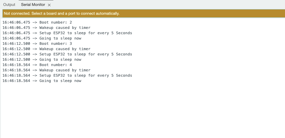
Sueño Ligero
Introducción
El modo de Sueño Ligero es otro modo de bajo consumo en el ESP32 que permite al dispositivo conservar energía mientras mantiene un tiempo de respuesta rápido. En este modo, los núcleos de la CPU se detienen, pero la RAM y algunos periféricos permanecen encendidos, permitiendo que el dispositivo se despierte rápidamente en respuesta a ciertos eventos.
El Sueño Ligero es ideal para aplicaciones que requieren bajo consumo de energía pero aún necesitan mantener una conexión a WiFi o Bluetooth, ya que permite que los módulos de comunicación inalámbrica permanezcan activos.
Métodos de Despertar
- Despertar por Temporizador: El dispositivo puede despertarse después de un período de tiempo especificado, permitiendo que se ejecuten tareas periódicas.
- Despertar por Interrupción Externa: El ESP32 puede ser despertado por señales externas, como pulsaciones de botones u otras interrupciones de hardware.
- Despertar por Actividad de Red: El dispositivo puede despertarse en respuesta a paquetes de red entrantes, habilitando comunicación eficiente sin estar constantemente en un estado activo.
- Despertar por GPIO: Pines GPIO específicos pueden ser configurados para despertar el dispositivo del Sueño Ligero cuando ocurre un evento, como un cambio de estado o señal.
Realización del Código
#include <freertos/FreeRTOS.h>
#include <freertos/task.h>

const int sleepTime = 10000;
const int ledPin = LED_BUILTIN;

void ledTask(void *pvParameters) {
  digitalWrite(ledPin, HIGH);
  Serial.println("LED is ON");
  vTaskDelay(pdMS_TO_TICKS(1000));
  digitalWrite(ledPin, LOW);
  Serial.println("LED is OFF");

  vTaskDelete(NULL);
}

void setup() {
  Serial.begin(115200);
  pinMode(ledPin, OUTPUT);
  Serial.println("Setup complete. Going to sleep...");
}

void loop() {
  esp_sleep_enable_timer_wakeup(sleepTime * 1000);
  Serial.println("Going to sleep now...");
  esp_light_sleep_start();

  xTaskCreate(ledTask, "LED Task", 2048, NULL, 1, NULL);

  delay(1000);
}
Notas Detalladas
#include <freertos/FreeRTOS.h>
#include <freertos/task.h>
- Incluir biblioteca FreeRTOS
const int sleepTime = 10000;
const int ledPin = LED_BUILTIN;
- Establecer el tiempo de suspensión a 10 segundos
- Usar el pin LED incorporado
void ledTask(void *pvParameters):
- Define una tarea de FreeRTOS para controlar el estado del LED.
digitalWrite(ledPin, HIGH);
Serial.println("LED is ON");
vTaskDelay(pdMS_TO_TICKS(1000));
digitalWrite(ledPin, LOW);
Serial.println("LED is OFF");
vTaskDelete(NULL);
vTaskDelay(pdMS_TO_TICKS(1000));Mantener el LED encendido durante 1 segundovTaskDelete(NULL);Eliminar la tarea actual
esp_sleep_enable_timer_wakeup(sleepTime * 1000);
Serial.println("Going to sleep now...");
esp_light_sleep_start();
xTaskCreate(ledTask, "LED Task", 2048, NULL, 1, NULL);
delay(1000);
esp_sleep_enable_timer_wakeup(sleepTime * 1000);Configurar temporizador para despertaresp_light_sleep_start();Entrar en modo de sueño ligeroxTaskCreate(ledTask, "LED Task", 2048, NULL, 1, NULL);Crear tarea de control LED
Mostrar Resultados
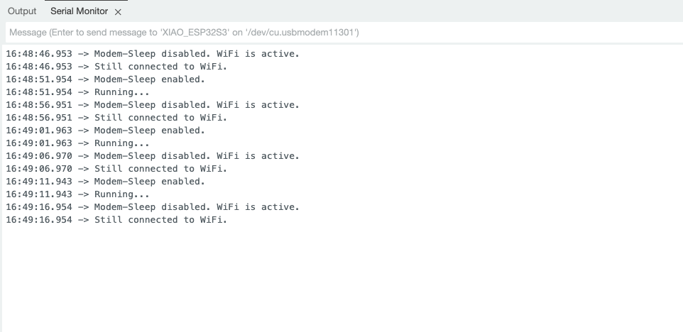
Modem-Sleep
Introducción
El modo Modem Sleep es otro modo de bajo consumo importante en ESP32, que es diferente del modo Deep Sleep. El modo Modem Sleep está optimizado principalmente para el módulo de comunicación inalámbrica del ESP32.
En este modo, el módulo WiFi/Bluetooth del ESP32 entra en estado de sueño, mientras que los núcleos de CPU permanecen activos. Esto permite al ESP32 mantener un cierto nivel de conectividad inalámbrica mientras reduce significativamente el consumo de energía.
Métodos de Despertar
-
Despertar por Temporizador
-
Despertar por Interrupción Externa
-
Despertar por Tarea
-
Despertar por Actividad de Red
Realización del Código
#include "WiFi.h"

void setup() {
    Serial.begin(115200);
    Serial.println("Connecting to WiFi...");

    WiFi.begin("****", "****");

    while (WiFi.status() != WL_CONNECTED) {
        delay(1000);
        Serial.println("Connecting...");
    }
    Serial.println("Connected to WiFi!");

    WiFi.setSleep(true);
    Serial.println("Modem-Sleep enabled.");
}

void loop() {

    Serial.println("Running...");

    delay(5000);

    WiFi.setSleep(false);
    Serial.println("Modem-Sleep disabled. WiFi is active.");

    if (WiFi.status() == WL_CONNECTED) {
        Serial.println("Still connected to WiFi.");
    } else {
        Serial.println("WiFi disconnected.");
    }

    delay(5000);
    WiFi.setSleep(true);
    Serial.println("Modem-Sleep enabled.");
}
Notas Detalladas
#include "WiFi.h"
- Incluye la biblioteca WiFi para habilitar las funciones WiFi.
Serial.println("Connecting to WiFi...");
- Imprime un mensaje indicando que la conexión a WiFi está iniciando.
WiFi.begin("****", "****");
- Comienza la conexión a la red WiFi especificada.
    while (WiFi.status() != WL_CONNECTED) {
        delay(1000);
        Serial.println("Connecting...");
    }
    Serial.println("Connected to WiFi!");
- Bucle hasta conectarse exitosamente al WiFi.
WiFi.setSleep(true);
- Habilita el modo de suspensión del módem para ahorrar energía.
WiFi.setSleep(false);
- Desactiva el modo de suspensión del módem para activar WiFi.
if (WiFi.status() == WL_CONNECTED) {
- Verificar el estado del WiFi.
WiFi.setSleep(true);
- Habilitar nuevamente el modo de suspensión del módem.
Mostrar Resultados
Aplicación de la Función de Suspensión
Con el ejemplo simple anterior, ahora vamos a dar un paso más y usar estas características de suspensión en el sensor ESP32 S3 Sense.
Preparación de Software
Antes de comenzar este artículo, asegúrese de haber completado algunas preparaciones de instalación de software si aún no ha utilizado todas las características de hardware en el XIAO ESP32S3 Sense.
Aquí hay introducciones a tres funcionalidades, y puede encontrar más información a través de los siguientes enlaces:
-
Uso del Micrófono: Aprenda cómo usar el micrófono en el XIAO ESP32S3 Sense para capturar niveles de sonido ambiental y grabar audio.
-
MicroSD: Comprenda cómo usar una tarjeta MicroSD para almacenamiento de datos, asegurándose de que pueda guardar y recuperar archivos en sus proyectos.
-
Uso de la Cámara: Domine cómo usar el módulo de cámara en el XIAO ESP32S3 Sense para tomar fotos y grabar videos.
Realización del Código
- Deep-Sleep
- Light-Sleep
- Modem-Sleep
#include "esp_camera.h"
#include "FS.h"
#include "SD.h"
#include "SPI.h"

#define CAMERA_MODEL_XIAO_ESP32S3

#include "camera_pins.h"

unsigned long lastCaptureTime = 0;
int imageCount = 1;
bool camera_sign = false;
bool sd_sign = false;


void photo_save(const char * fileName) {
  camera_fb_t *fb = esp_camera_fb_get();
  if (!fb) {
    Serial.println("Failed to get camera frame buffer");
    return;
  }
  writeFile(SD, fileName, fb->buf, fb->len);

  esp_camera_fb_return(fb);

  Serial.println("Photo saved to file");
}

void writeFile(fs::FS &fs, const char * path, uint8_t * data, size_t len){
    Serial.printf("Writing file: %s\r\n", path);

    File file = fs.open(path, FILE_WRITE);
    if (!file) {
        Serial.println("Failed to open file for writing");
        return;
    }
    if (file.write(data, len) == len) {
        Serial.println("File written");
    } else {
        Serial.println("Write failed");
    }
    file.close();
}

void setup() {
  Serial.begin(115200);
  while (!Serial);

  camera_config_t config;
  config.ledc_channel = LEDC_CHANNEL_0;
  config.ledc_timer = LEDC_TIMER_0;
  config.pin_d0 = Y2_GPIO_NUM;
  config.pin_d1 = Y3_GPIO_NUM;
  config.pin_d2 = Y4_GPIO_NUM;
  config.pin_d3 = Y5_GPIO_NUM;
  config.pin_d4 = Y6_GPIO_NUM;
  config.pin_d5 = Y7_GPIO_NUM;
  config.pin_d6 = Y8_GPIO_NUM;
  config.pin_d7 = Y9_GPIO_NUM;
  config.pin_xclk = XCLK_GPIO_NUM;
  config.pin_pclk = PCLK_GPIO_NUM;
  config.pin_vsync = VSYNC_GPIO_NUM;
  config.pin_href = HREF_GPIO_NUM;
  config.pin_sscb_sda = SIOD_GPIO_NUM;
  config.pin_sscb_scl = SIOC_GPIO_NUM;
  config.pin_pwdn = PWDN_GPIO_NUM;
  config.pin_reset = RESET_GPIO_NUM;
  config.xclk_freq_hz = 20000000;
  config.frame_size = FRAMESIZE_UXGA;
  config.pixel_format = PIXFORMAT_JPEG;
  config.grab_mode = CAMERA_GRAB_WHEN_EMPTY;
  config.fb_location = CAMERA_FB_IN_PSRAM;
  config.jpeg_quality = 12;
  config.fb_count = 1;

  esp_err_t err = esp_camera_init(&config);
  if (err != ESP_OK) {
    Serial.printf("Camera init failed with error 0x%x", err);
    return;
  }

  camera_sign = true;

  if (!SD.begin(21)) {
    Serial.println("Card Mount Failed");
    return;
  }

  uint8_t cardType = SD.cardType();

  if (cardType == CARD_NONE) {
    Serial.println("No SD card attached");
    return;
  }

  Serial.print("SD Card Type: ");
  if (cardType == CARD_MMC) {
    Serial.println("MMC");
  } else if (cardType == CARD_SD) {
    Serial.println("SDSC");
  } else if (cardType == CARD_SDHC) {
    Serial.println("SDHC");
  } else {
    Serial.println("UNKNOWN");
  }

  sd_sign = true;

  Serial.println("Photos will begin shortly, please be ready.");
}

void loop() {
  if (camera_sign && sd_sign) {
    unsigned long now = millis();

    if ((now - lastCaptureTime) >= 60000) {
      char filename[32];
      sprintf(filename, "/image%d.jpg", imageCount);
      photo_save(filename);
      Serial.printf("Saved picture: %s\r\n", filename);
      Serial.println("Entering deep sleep for 10 seconds...");

      esp_sleep_enable_timer_wakeup(10000000);
      esp_deep_sleep_start();

    }
  }
}
Notas Detalladas
Este código implementa un sistema de captura de imágenes basado en el módulo de cámara ESP32, que puede tomar automáticamente una foto cada 60 segundos y guardarla en la tarjeta SD. En la función void setup(), se inicializan la cámara y la tarjeta SD y se confirma el estado del dispositivo; en la función void loop(), se verifica si la cámara puede tomar una foto, y si se cumple la condición, se llama a la función photo_save() para guardar la imagen y entrar en un estado de sueño profundo durante 10 segundos después de guardar para ahorrar energía.
#include <ESP_I2S.h>
#include <freertos/FreeRTOS.h>
#include <freertos/task.h>

I2SClass I2S;

const int sleepTime = 10000;

void i2sTask(void *pvParameters) {
  Serial.println("start collecting");
  for (int i = 0; i < 10; i++) {
    int sample = I2S.read();
    if (sample && sample != -1 && sample != 1) {
      Serial.println(sample);
    }
    vTaskDelay(pdMS_TO_TICKS(1000));
  }
  vTaskDelay(pdMS_TO_TICKS(3000));
  vTaskDelete(NULL);
}

void setup() {
  Serial.begin(115200);
  while (!Serial) {
    ;
  }

  I2S.setPinsPdmRx(42, 41);

  if (!I2S.begin(I2S_MODE_PDM_RX, 16000, I2S_DATA_BIT_WIDTH_16BIT, I2S_SLOT_MODE_MONO)) {
    Serial.println("Failed to initialize I2S!");
    while (1);
  }
}

void loop() {
  esp_sleep_enable_timer_wakeup(sleepTime * 1000);
  xTaskCreate(i2sTask, "I2S Task", 2048, NULL, 1, NULL);

  Serial.println("Going to sleep now...");
  esp_light_sleep_start();

  delay(1000);
}
Notas Detalladas
Este código implementa la función de capturar datos de audio usando la interfaz I2S. En la función void setup(), se inicializan el puerto serie y la interfaz I2S; en la función void loop(), se habilita el temporizador de activación y se crea una tarea void i2sTask(void *pvParameters), que es responsable de leer muestras de audio e imprimir datos válidos cada segundo. Después de que la tarea se ha ejecutado 10 veces, se retrasa por 3 segundos y se elimina a sí misma.
#include "esp_camera.h"
#include <WiFi.h>

#define CAMERA_MODEL_XIAO_ESP32S3
#include "camera_pins.h"

const char *ssid = "******";
const char *password = "******";

void startCameraServer();
void setupLedFlash(int pin);

unsigned long lastCameraOperationTime = 0;
const unsigned long sleepDelay = 10000;

void setup() {
  Serial.begin(115200);
  Serial.setDebugOutput(true);
  Serial.println();

  camera_config_t config;
  config.ledc_channel = LEDC_CHANNEL_0;
  config.ledc_timer = LEDC_TIMER_0;
  config.pin_d0 = Y2_GPIO_NUM;
  config.pin_d1 = Y3_GPIO_NUM;
  config.pin_d2 = Y4_GPIO_NUM;
  config.pin_d3 = Y5_GPIO_NUM;
  config.pin_d4 = Y6_GPIO_NUM;
  config.pin_d5 = Y7_GPIO_NUM;
  config.pin_d6 = Y8_GPIO_NUM;
  config.pin_d7 = Y9_GPIO_NUM;
  config.pin_xclk = XCLK_GPIO_NUM;
  config.pin_pclk = PCLK_GPIO_NUM;
  config.pin_vsync = VSYNC_GPIO_NUM;
  config.pin_href = HREF_GPIO_NUM;
  config.pin_sccb_sda = SIOD_GPIO_NUM;
  config.pin_sccb_scl = SIOC_GPIO_NUM;
  config.pin_pwdn = PWDN_GPIO_NUM;
  config.pin_reset = RESET_GPIO_NUM;
  config.xclk_freq_hz = 20000000;
  config.frame_size = FRAMESIZE_UXGA;
  config.pixel_format = PIXFORMAT_JPEG;
  config.grab_mode = CAMERA_GRAB_WHEN_EMPTY;
  config.fb_location = CAMERA_FB_IN_PSRAM;
  config.jpeg_quality = 12;
  config.fb_count = 1;

  if (config.pixel_format == PIXFORMAT_JPEG) {
    if (psramFound()) {
      config.jpeg_quality = 10;
      config.fb_count = 2;
      config.grab_mode = CAMERA_GRAB_LATEST;
    } else {
      config.frame_size = FRAMESIZE_SVGA;
      config.fb_location = CAMERA_FB_IN_DRAM;
    }
  } else {
    config.frame_size = FRAMESIZE_240X240;
#if CONFIG_IDF_TARGET_ESP32S3
    config.fb_count = 2;
#endif
  }

#if defined(CAMERA_MODEL_ESP_EYE)
  pinMode(13, INPUT_PULLUP);
  pinMode(14, INPUT_PULLUP);
#endif

  esp_err_t err = esp_camera_init(&config);
  if (err != ESP_OK) {
    Serial.printf("Camera init failed with error 0x%x", err);
    return;
  }

  sensor_t *s = esp_camera_sensor_get();
  if (s->id.PID == OV3660_PID) {
    s->set_vflip(s, 1);
    s->set_brightness(s, 1);
    s->set_saturation(s, -2);
  }
  if (config.pixel_format == PIXFORMAT_JPEG) {
    s->set_framesize(s, FRAMESIZE_QVGA);
  }

#if defined(CAMERA_MODEL_M5STACK_WIDE) || defined(CAMERA_MODEL_M5STACK_ESP32CAM)
  s->set_vflip(s, 1);
  s->set_hmirror(s, 1);
#endif

#if defined(CAMERA_MODEL_ESP32S3_EYE)
  s->set_vflip(s, 1);
#endif

#if defined(LED_GPIO_NUM)
  setupLedFlash(LED_GPIO_NUM);
#endif

  WiFi.begin(ssid, password);
  WiFi.setSleep(false);

  while (WiFi.status() != WL_CONNECTED) {
    delay(500);
    Serial.print(".");
  }
  Serial.println("");
  Serial.println("WiFi connected");

  startCameraServer();

  Serial.print("Camera Ready! Use 'http://");
  Serial.print(WiFi.localIP());
  Serial.println("' to connect");
}

void loop() {
  delay(10000);

  if (WiFi.getSleep()) {
    Serial.println("WiFi is in sleep mode.");
  } else {
    Serial.println("WiFi is active.");
  }

  if (millis() - lastCameraOperationTime > sleepDelay) {
    WiFi.setSleep(true);
    Serial.println("No camera operation. WiFi is now in sleep mode.");
  } else {
    WiFi.setSleep(false);
  }
  cameraOperation();
}

void cameraOperation() {
  lastCameraOperationTime = millis();
}
Notas Detalladas
Este código implementa el uso del módulo de cámara ESP32 para captura de imágenes y conexión vía Wi-Fi. En la función void setup(), se inicializan el puerto serie, la cámara y la conexión Wi-Fi; si la inicialización es exitosa, el programa imprime la dirección Wi-Fi para que el usuario se conecte. En la función void loop(), el código verifica el estado del Wi-Fi cada 10 segundos, si no hay operación de cámara, el Wi-Fi se configurará en modo de suspensión para ahorrar energía. Cada llamada a la función cameraOperation() actualiza el tiempo de la última operación para asegurar que el Wi-Fi permanezca conectado durante el evento.
Estos códigos no pueden usarse directamente, necesitas añadir el archivo de cabecera sobre la cámara, por favor revisa el ejemplo anterior sobre XIAO ESP32 S3.
Para concluir
Por qué usar el modo Deep Sleep
maximizar el ahorro de energía sin comprometer la funcionalidad, con el fin de extender la vida útil de la batería del dispositivo. Escenarios adecuados: Aplicaciones donde la vida útil de la batería es crucial, como nodos de sensores remotos, dispositivos portátiles y otros dispositivos IoT de bajo consumo. Aunque el tiempo de activación es relativamente lento, este compromiso vale la pena.
Por qué usar el modo Modem Sleep
optimizar el consumo de energía del módulo de comunicación inalámbrica, mientras se mantiene la conectividad de red. Escenarios adecuados: Aplicaciones que necesitan mantener conexión de red pero también requieren bajo consumo, como dispositivos IoT que funcionan intermitentemente. Modem Sleep puede reducir significativamente el consumo de energía del módulo inalámbrico mientras proporciona una respuesta de activación rápida.
En resumen
estos tres modos de suspensión proporcionan a los desarrolladores diferentes opciones de compromiso entre energía/rendimiento que pueden elegirse flexiblemente según los requisitos específicos de la aplicación. Para dispositivos con requisitos de vida útil de batería, el modo Deep Sleep es una buena opción; y para dispositivos IoT que necesitan mantener conectividad de red, el modo Modem Sleep es la opción óptima.
Soporte Técnico y Discusión de Productos
¡Gracias por elegir nuestros productos! Estamos aquí para proporcionarte diferentes tipos de soporte para asegurar que tu experiencia con nuestros productos sea lo más fluida posible. Ofrecemos varios canales de comunicación para atender diferentes preferencias y necesidades.