Controlando GPIO del reSpeaker XVF3800 a través del XIAO ESP32-S3
Objetivo
Esta guía explica cómo leer y controlar pines GPIO en el procesador de voz XVF3800 usando la interfaz I2C. Aprenderás cómo:
- Leer estados de pines GPI y GPO
- Controlar pines de salida (ej., silenciar micrófono, controlar LED, amplificador)
- Entender mapeos GPIO y su propósito
Descripción General de GPIO
El reSpeaker XVF3800 expone 3 pines de entrada (GPI) y 5 pines de salida (GPO) para control externo. Puedes usarlos para leer estados de botones o controlar hardware como el LED de silencio, amplificador o LEDs.
| Nombre del Pin | Dirección | Función |
|---|---|---|
| X1D09 | Entrada (RO) | Estado del botón de silencio (alto cuando se libera) |
| X1D13 | Entrada (RO) | Flotante |
| X1D34 | Entrada (RO) | Flotante |
| X0D11 | Salida (RW) | Flotante |
| X0D30 | Salida (RW) | LED de silencio + control de silencio de micrófono (alto = silencio) |
| X0D31 | Salida (RW) | Habilitación de amplificador (bajo = habilitado) |
| X0D33 | Salida (RW) | Control de alimentación LED WS2812 (alto = encendido) |
| X0D39 | Salida (RW) | Flotante |
Leer Estados de Pines GPO
Objetivo: Verificar niveles lógicos de todos los GPIOs capaces de salida (GPOs). Aspectos Destacados del Código:
- Envía una solicitud de lectura usando:
- ID de Recurso: 20 (GPO)
- ID de Comando: 0 (GPO_READ_VALUES)
- Lee estados de 5 pines GPO en orden: X0D11 → X0D30 → X0D31 → X0D33 → X0D39
- Incluye un byte de estado para validar la respuesta
#include <Wire.h>
#define XMOS_ADDR 0x2C // I2C 7-bit address
#define GPO_SERVICER_RESID 20
#define GPO_SERVICER_RESID_GPO_READ_VALUES 0
#define GPO_GPO_READ_NUM_BYTES 5
void setup() {
Serial.begin(115200);
while (!Serial);
Wire.begin();
delay(1000);
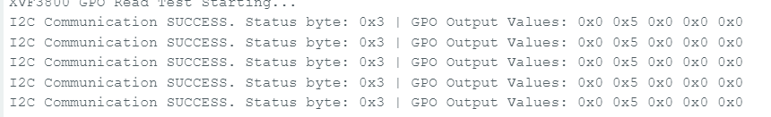
Serial.println("XVF3800 GPO Read Test Starting...");
}
void loop() {
uint8_t gpo_values[GPO_GPO_READ_NUM_BYTES] = {0};
uint8_t status = 0xFF;
bool success = read_gpo_values(gpo_values, &status);
if (success) {
Serial.print("I2C Communication SUCCESS. Status byte: 0x");
Serial.print(status, HEX);
Serial.print(" | GPO Output Values: ");
for (uint8_t i = 0; i < GPO_GPO_READ_NUM_BYTES; i++) {
Serial.print("0x");
Serial.print(gpo_values[i], HEX);
Serial.print(" ");
}
Serial.println();
} else {
Serial.println("Failed to read GPO values.");
}
delay(1000);
}
bool read_gpo_values(uint8_t *buffer, uint8_t *status) {
const uint8_t resid = GPO_SERVICER_RESID;
const uint8_t cmd = GPO_SERVICER_RESID_GPO_READ_VALUES | 0x80;
const uint8_t read_len = GPO_GPO_READ_NUM_BYTES;
// Step 1: Write command
Wire.beginTransmission(XMOS_ADDR);
Wire.write(resid);
Wire.write(cmd);
Wire.write(read_len + 1);
uint8_t result = Wire.endTransmission();
if (result != 0) {
Serial.print("I2C Write Error: ");
Serial.println(result);
return false;
}
// Step 2: Read response (status + payload)
Wire.requestFrom(XMOS_ADDR, (uint8_t)(read_len + 1));
if (Wire.available() < read_len + 1) {
Serial.println("I2C Read Error: Not enough data received.");
return false;
}
*status = Wire.read();
for (uint8_t i = 0; i < read_len; i++) {
buffer[i] = Wire.read();
}
return true;
}
Leer Estados de Pines GPI
Objetivo: Verificar estados de GPIOs capaces de entrada (ej., estado del botón de silencio). Aspectos Destacados del Código:
- Envía comando a:
- ID de Recurso: 36 (IO_CONFIG)
- ID de Comando: 6 (GPI_VALUE_ALL)
- Recibe 3 GPI representando el estado de X1D09, X1D13, y X1D34
#include <Wire.h>
#define XMOS_ADDR 0x2C // I2C 7-bit address of XVF3800
// Resource and command IDs for GPI
#define IO_CONFIG_SERVICER_RESID 36
#define IO_CONFIG_SERVICER_RESID_GPI_READ_VALUES 0
#define GPI_READ_NUM_BYTES 3 // From header: IO_CONFIG_SERVICER_RESID_GPI_READ_VALUES_NUM_VALUES
void setup() {
Serial.begin(115200);
while (!Serial);
Wire.begin();
delay(1000);
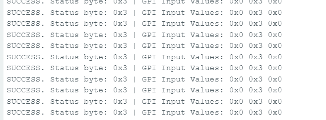
Serial.println("XVF3800 GPI Read Test Starting...");
}
void loop() {
uint8_t gpi_values[GPI_READ_NUM_BYTES] = {0};
uint8_t status = 0xFF;
bool success = read_gpi_values(gpi_values, &status);
if (success) {
Serial.print("I2C Communication SUCCESS. Status byte: 0x");
Serial.print(status, HEX);
Serial.print(" | GPI Input Values: ");
for (uint8_t i = 0; i < GPI_READ_NUM_BYTES; i++) {
Serial.print("0x");
Serial.print(gpi_values[i], HEX);
Serial.print(" ");
}
Serial.println();
} else {
Serial.println("Failed to read GPI values.");
}
delay(1000);
}
bool read_gpi_values(uint8_t *buffer, uint8_t *status) {
const uint8_t resid = IO_CONFIG_SERVICER_RESID;
const uint8_t cmd = IO_CONFIG_SERVICER_RESID_GPI_READ_VALUES | 0x80; // Read command
const uint8_t read_len = GPI_READ_NUM_BYTES;
// Step 1: Send the command
Wire.beginTransmission(XMOS_ADDR);
Wire.write(resid);
Wire.write(cmd);
Wire.write(read_len + 1); // +1 for status byte
uint8_t result = Wire.endTransmission();
if (result != 0) {
Serial.print("I2C Write Error: ");
Serial.println(result);
return false;
}
// Step 2: Read response (status + payload)
Wire.requestFrom(XMOS_ADDR, (uint8_t)(read_len + 1));
if (Wire.available() < read_len + 1) {
Serial.println("I2C Read Error: Not enough data received.");
return false;
}
*status = Wire.read(); // first byte is status
for (uint8_t i = 0; i < read_len; i++) {
buffer[i] = Wire.read();
}
return true;
}
Escribir a Pin GPO – Ejemplo de Silenciar Micrófono
Objetivo: Controlar un GPIO de salida, ej., silenciar micrófono alternando GPIO 30 (X0D30). Aspectos Destacados del Código:
- Envía un comando de escritura a:
- ID de Recurso: 20
- ID de Comando: 1 (GPO_WRITE_VALUE)
- Carga útil: número de pin, valor
ej., {30, 1} para silenciar
Funciones de Conveniencia:
- muteMic() → establece GPIO 30 en ALTO para silenciar micrófono y encender LED rojo
- unmuteMic() → establece GPIO 30 en BAJO para activar micrófono y apagar LED
#include <Wire.h>

// Define the 7-bit I2C address of the XVF3800 device
#define XMOS_ADDR 0x2C

// Define XVF3800 Resource and Command IDs
#define GPO_SERVICER_RESID 20                         // Resource ID for GPIO Output (GPO)
#define GPO_SERVICER_RESID_GPO_WRITE_VALUE 1          // Command ID to write value to GPIO
#define IO_CONFIG_SERVICER_RESID 36                   // Resource ID for IO Configuration
#define IO_CONFIG_SERVICER_RESID_GPI_VALUE_ALL 6      // Command ID to read all GPIO input values

void setup() {
  Wire.begin();                 // Initialize I2C communication
  Serial.begin(115200);        // Initialize serial communication for debugging
  delay(1000);                 // Short delay to allow device startup

  Serial.println("Muting Mic (Setting GPIO 30 HIGH)");
  muteMic();                   // Set GPIO 30 HIGH to mute microphone
  delay(5000);                 // Wait for 5 seconds

  Serial.println("Unmuting Mic (Setting GPIO 30 LOW)");
  unmuteMic();                 // Set GPIO 30 LOW to unmute microphone
  delay(3000);                 // Wait for 3 seconds

  Serial.println("Reading GPIO Status...");
  readGPIOStatus();            // Read and print the status of all GPIOs
}

void loop() {
  // Empty loop - no repeated actions for now
}

// Function to set GPIO 30 to a specific logic level (0 = LOW, 1 = HIGH)
void setGPIO30(uint8_t level) {
  uint8_t payload[2] = {30, level};  // Payload format: [GPIO index, value]
  xmos_write_bytes(GPO_SERVICER_RESID, GPO_SERVICER_RESID_GPO_WRITE_VALUE, payload, 2);

  Serial.print("Command Sent: GPIO 30 = ");
  Serial.println(level);
}

// Convenience function to mute the microphone (set GPIO 30 HIGH)
void muteMic() {
  setGPIO30(1);  // Logic HIGH to mute
}

// Convenience function to unmute the microphone (set GPIO 30 LOW)
void unmuteMic() {
  setGPIO30(0);  // Logic LOW to unmute
}

// Function to write a sequence of bytes over I2C to the XVF3800
void xmos_write_bytes(uint8_t resid, uint8_t cmd, uint8_t *value, uint8_t write_byte_num) {
  Wire.beginTransmission(XMOS_ADDR); // Begin I2C transmission to XVF3800
  Wire.write(resid);                 // Write the resource ID
  Wire.write(cmd);                   // Write the command ID
  Wire.write(write_byte_num);       // Write number of payload bytes
  for (uint8_t i = 0; i < write_byte_num; i++) {
    Wire.write(value[i]);           // Write each payload byte
  }
  Wire.endTransmission();           // End the I2C transmission
}

// Function to read the status of all GPIO inputs (32 bits) from XVF3800
void readGPIOStatus() {
  uint8_t buffer[4] = {0};  // Buffer to hold the 4-byte GPIO status response

  // --- Write phase: Send read request ---
  Wire.beginTransmission(XMOS_ADDR);                        // Begin I2C write transaction
  Wire.write(IO_CONFIG_SERVICER_RESID);                     // Write the resource ID for IO config
  Wire.write(IO_CONFIG_SERVICER_RESID_GPI_VALUE_ALL);       // Write the command ID to get all GPIO values
  Wire.write(1);                                             // Payload length (1 byte)
  Wire.endTransmission(false);                              // End transmission with repeated start (no stop)

  // --- Read phase: Read response from device ---
  Wire.requestFrom(XMOS_ADDR, 5); // Request 5 bytes: 1 status byte + 4 data bytes

  if (Wire.available() < 5) {
    Serial.println("Error: Not enough bytes received from XVF3800.");
    return;
  }

  uint8_t status = Wire.read();  // Read the status byte (should be 0 for success)

  // Read the 4-byte GPIO input status value
  for (int i = 0; i < 4; i++) {
    buffer[i] = Wire.read();
  }

  // Combine 4 bytes into a single 32-bit unsigned integer
  uint32_t gpio_status = ((uint32_t)buffer[3] << 24) |
                         ((uint32_t)buffer[2] << 16) |
                         ((uint32_t)buffer[1] << 8)  |
                         ((uint32_t)buffer[0]);

  Serial.print("GPIO Status Register = 0x");
  Serial.println(gpio_status, HEX);

  // Check and print the state of GPIO 30 specifically
  bool gpio30 = (gpio_status >> 30) & 0x01;
  Serial.print("GPIO 30 State: ");
  Serial.println(gpio30 ? "HIGH (Muted)" : "LOW (Unmuted)");
}
Soporte Técnico y Discusión de Productos
¡Gracias por elegir nuestros productos! Estamos aquí para brindarle diferentes tipos de soporte para asegurar que su experiencia con nuestros productos sea lo más fluida posible. Ofrecemos varios canales de comunicación para satisfacer diferentes preferencias y necesidades.