Arduino Cookbook: Pantalla de tinta electrónica (reTerminal E Serie)
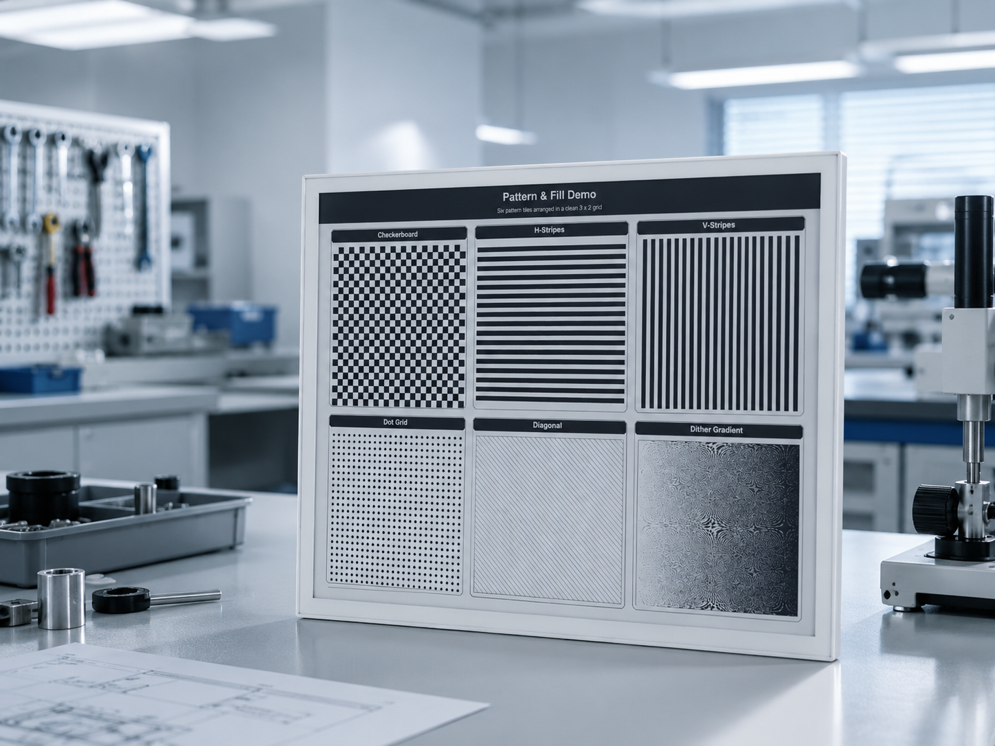
Si quieres previsualizar rápidamente los resultados del proyecto o probar el firmware demo básico antes de configurar un entorno de desarrollo, abre el reTerminal E-Series Firmware Hub. Puedes elegir un dispositivo compatible de reTerminal E Serie y flashear firmware de demostración directamente desde un navegador.
Esta página se centra en controlar la pantalla de tinta electrónica desde Arduino. Si quieres usar el LED integrado, el zumbador, los botones, el sensor SHT4x, el monitor de batería o la ranura para tarjeta microSD, dirígete a Arduino Cookbook: Periféricos integrados. Para el RTC, modos de bajo consumo, el micrófono integrado y el dibujo con toque capacitivo, consulta Arduino Cookbook: RTC, Bajo Consumo, Audio y Táctil.
El código base compartido — configuración del IDE de Arduino, paquete de placas ESP32, instalación de Seeed_GFX, generación de driver.h — también se encuentra en Trabajar con Arduino. Échale un vistazo primero si eres nuevo en Arduino en pantallas de tinta electrónica de Seeed.
Introducción
La reTerminal E Serie es la línea HMI industrial de Seeed Studio, basada en la XIAO ESP32-S3 y que incorpora pantallas de tinta electrónica integradas. Este cookbook te guía por todo lo que necesitas para renderizar texto, gráficos e imágenes en la pantalla:
- Descripción de hardware y enlaces de compra para E1001 / E1002 / E1003 / E1004.
- Configuración del entorno del IDE de Arduino para los cuatro modelos (placa XIAO_ESP32S3, OPI PSRAM).
- Un primer Hello World en cada modelo usando la biblioteca Seeed_GFX (con el
BOARD_SCREEN_COMBOcorrespondiente). - Ejemplos avanzados específicos de cada panel con Seeed_GFX — escala de grises de 4 niveles en E1001 y escala de grises de 16 niveles en E1003.
- Un Hello World alternativo usando la popular biblioteca GxEPD2.
- Consejos de resolución de problemas para fallos de refresco de la pantalla de tinta electrónica y errores de carga.
Materiales necesarios
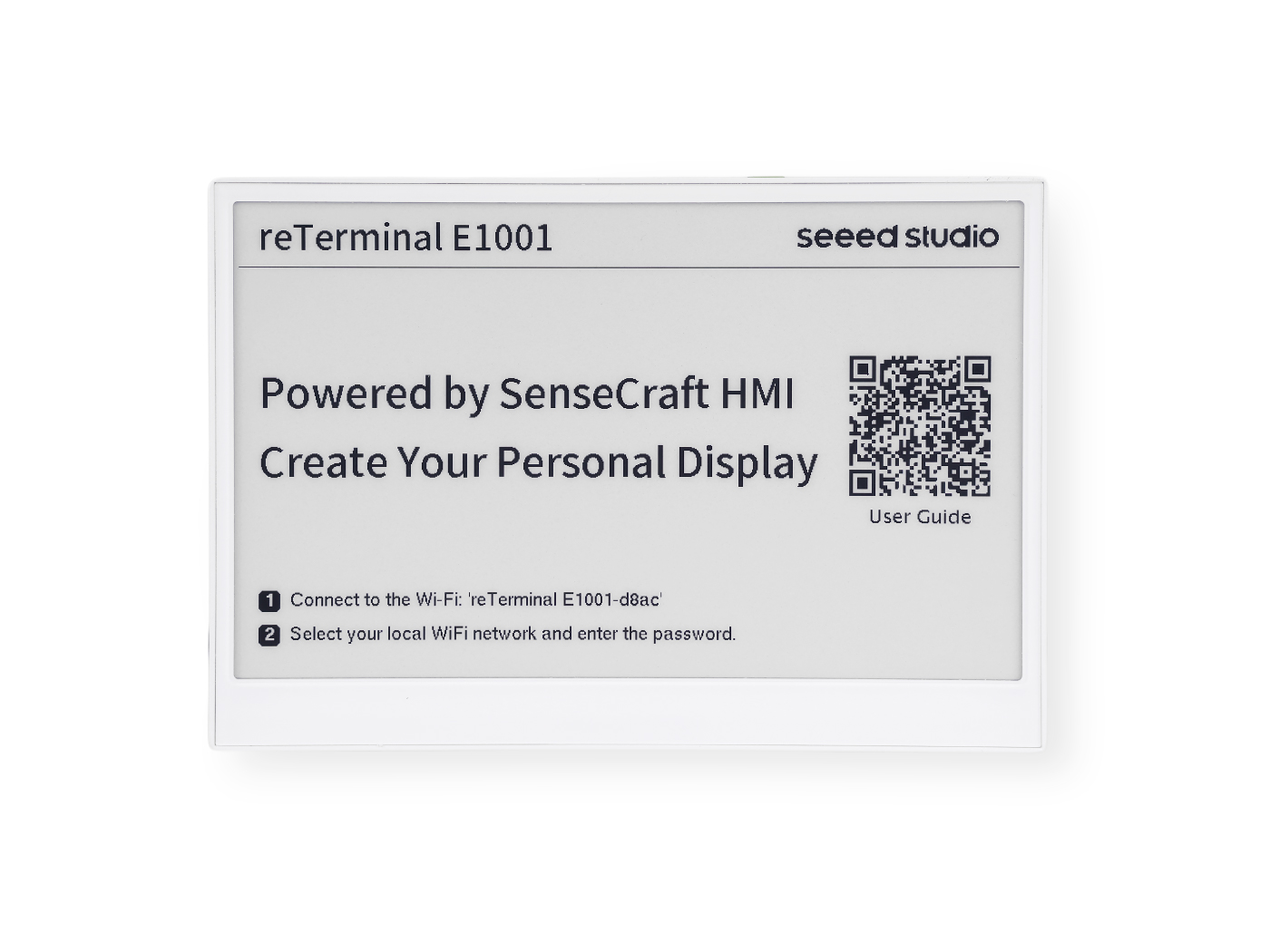
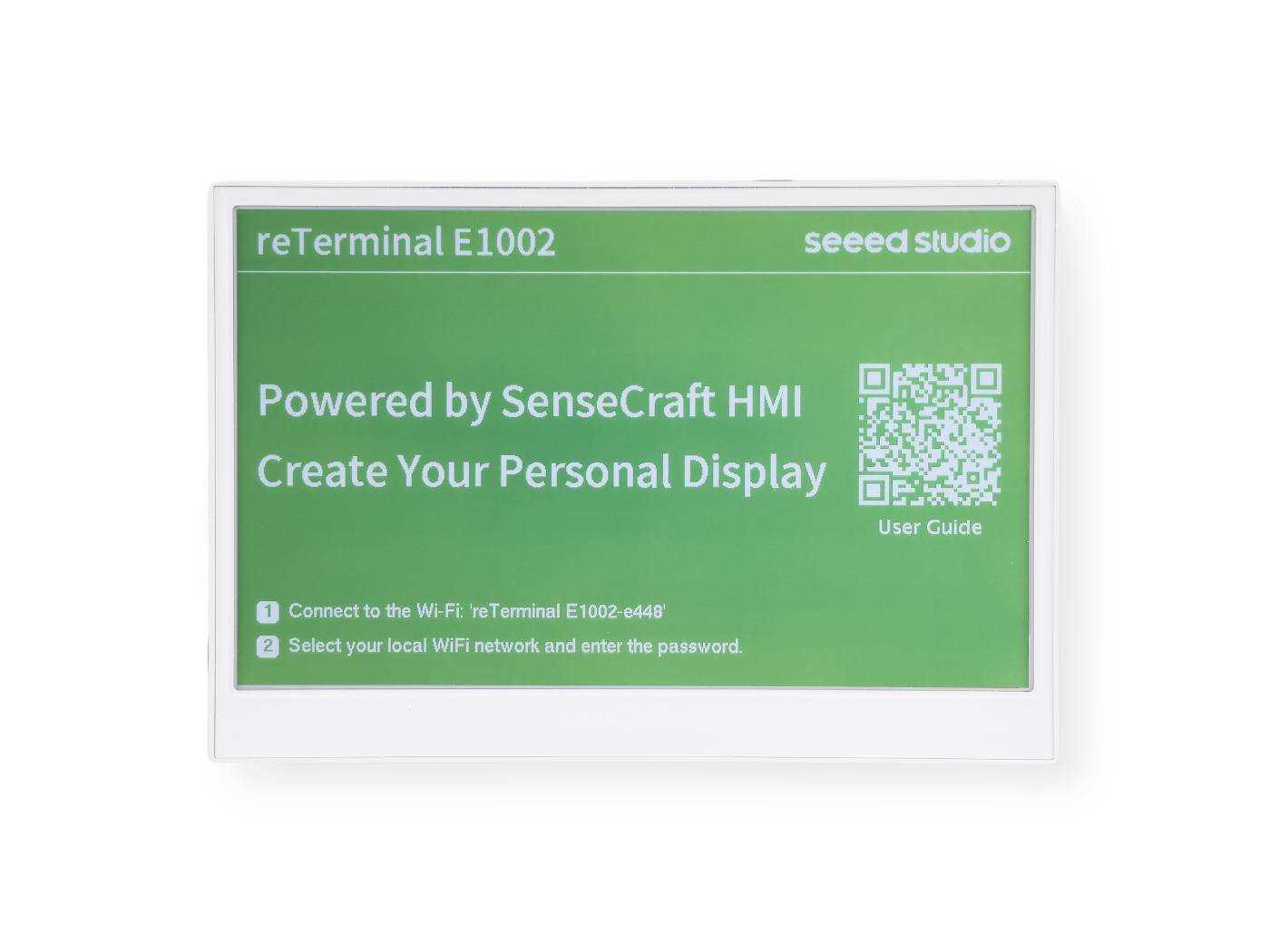
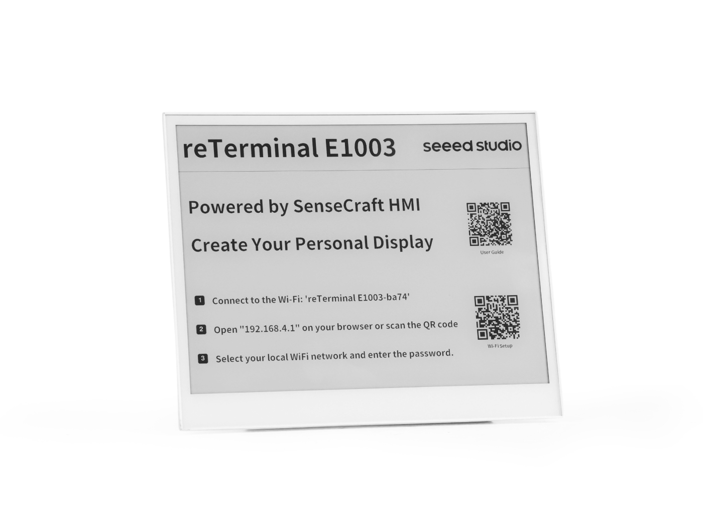
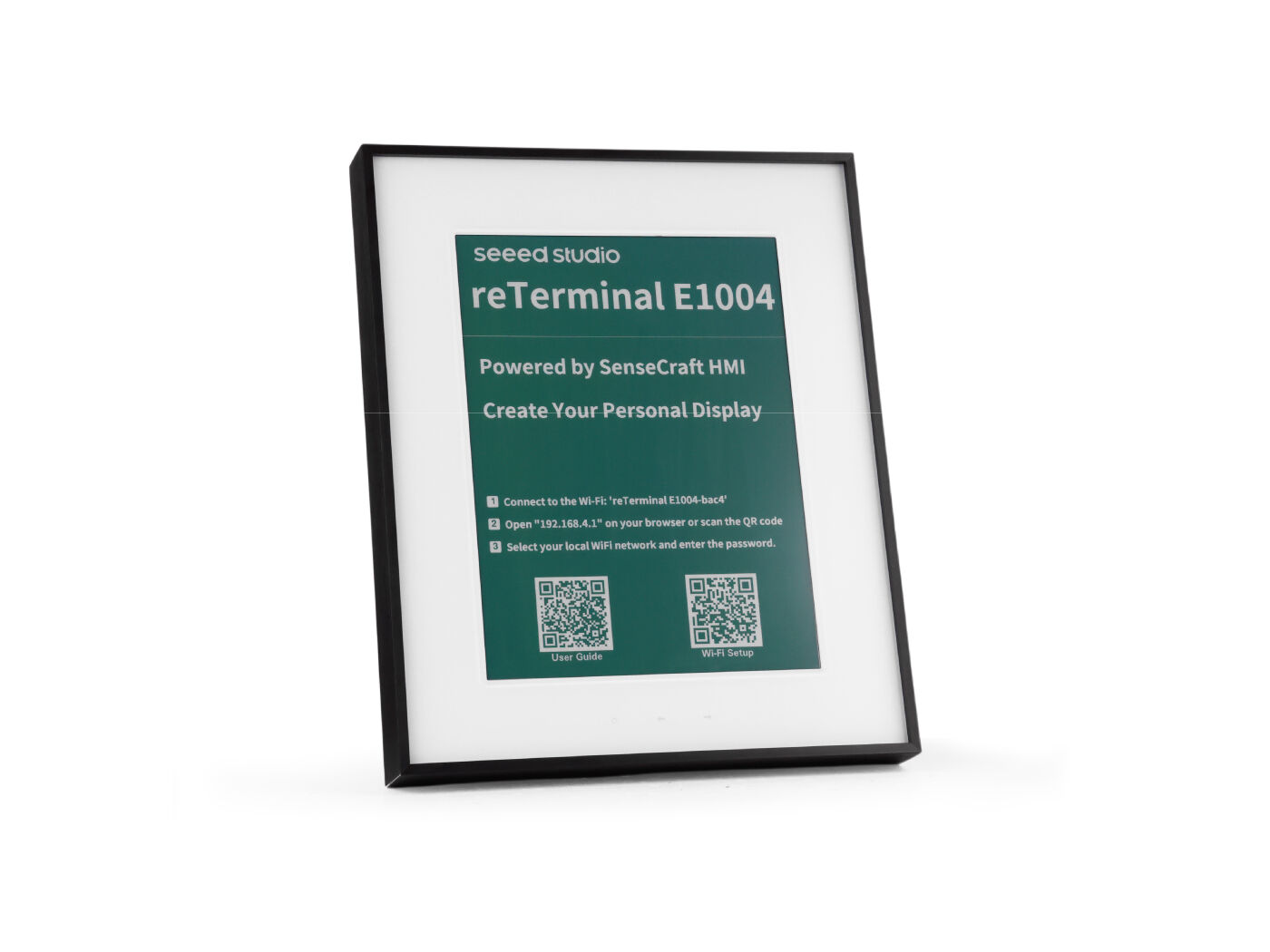
Para completar este tutorial, prepara uno de los siguientes dispositivos reTerminal E Serie:
| reTerminal E1001 | reTerminal E1002 | reTerminal E1003 | reTerminal E1004 |
|---|---|---|---|
 |  |  |  |
Preparación del entorno
Para programar la pantalla de tinta electrónica de reTerminal E Serie con Arduino, necesitarás configurar el IDE de Arduino con soporte para ESP32.
Si es la primera vez que usas Arduino, te recomendamos encarecidamente que consultes Getting Started with Arduino.
Configuración del IDE de Arduino
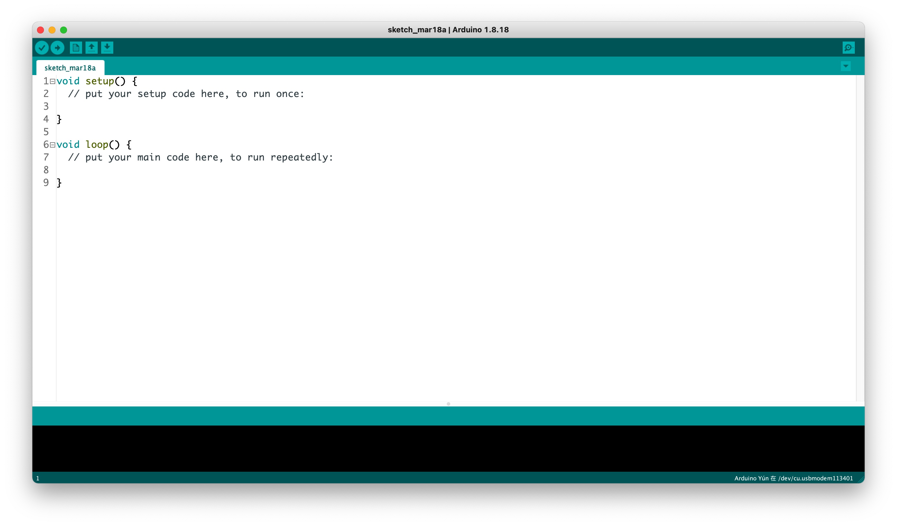
Paso 1. Descarga e instala el IDE de Arduino y lanza la aplicación de Arduino.
Paso 2. Añade soporte para la placa ESP32 al IDE de Arduino.
En el IDE de Arduino, ve a File > Preferences y añade la siguiente URL en el campo "Additional Boards Manager URLs":
https://raw.githubusercontent.com/espressif/arduino-esp32/gh-pages/package_esp32_index.json
Paso 3. Instala el paquete de placas ESP32.
Navega a Tools > Board > Boards Manager, busca "esp32" e instala el paquete ESP32 de Espressif Systems.
Paso 4. Selecciona la placa correcta.
Ve a Tools > Board > ESP32 Arduino y selecciona XIAO_ESP32S3.
Paso 5. Conecta tu pantalla de tinta electrónica reTerminal E Serie a tu ordenador usando un cable USB-C.
Paso 6. Selecciona el puerto correcto desde Tools > Port.
Programación de la pantalla de tinta electrónica
El reTerminal E1001 incorpora una pantalla de tinta electrónica en blanco y negro de 7,5 pulgadas, mientras que el reTerminal E1002 está equipado con una pantalla de tinta electrónica a todo color de 7,3 pulgadas. Ambas pantallas ofrecen una excelente visibilidad en diversas condiciones de iluminación con un consumo de energía ultrabajo, lo que las hace ideales para aplicaciones industriales que requieren pantallas siempre encendidas con un consumo mínimo de energía.
Uso de la biblioteca Seeed_GFX
Para controlar la pantalla de tinta electrónica, usaremos la biblioteca Seeed_GFX, que proporciona soporte completo para varios dispositivos de visualización de Seeed Studio.
Paso 1. Descarga la biblioteca Seeed_GFX desde GitHub:
Paso 2. Instala la biblioteca añadiendo el archivo ZIP en el IDE de Arduino. Ve a Sketch > Include Library > Add .ZIP Library y selecciona el archivo ZIP descargado.
Si has instalado previamente la biblioteca TFT_eSPI, puede que necesites eliminarla temporalmente o cambiarle el nombre en la carpeta de bibliotecas de Arduino para evitar conflictos, ya que Seeed_GFX es un fork de TFT_eSPI con funciones adicionales para pantallas de Seeed Studio.
- Programar reTerminal E1001
- Programming reTerminal E1002
- Programming reTerminal E1003
- Programming reTerminal E1004
Programar reTerminal E1001 (pantalla de tinta electrónica en blanco y negro de 7,5 pulgadas)
Vamos a explorar un ejemplo sencillo que demuestra operaciones básicas de dibujo en la pantalla de tinta electrónica en blanco y negro.
Paso 1. Abre el sketch de ejemplo de la biblioteca Seeed_GFX: File > Examples > Seeed_GFX > ePaper > Basic > HelloWorld
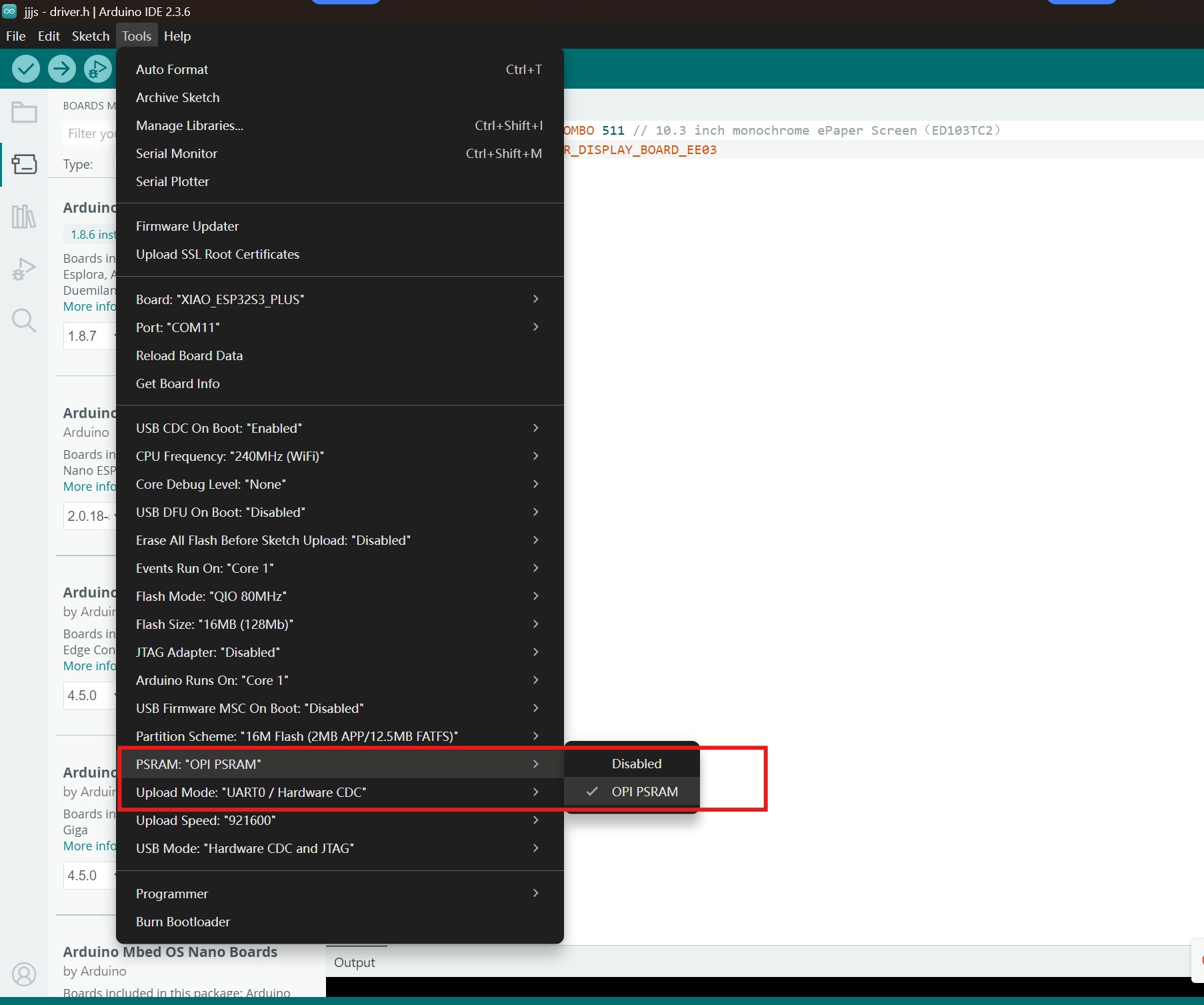
Paso 2. Activa OPI PSRAM en el IDE de Arduino: Tools > PSRAM > OPI PSRAM
Paso 3. Crea un nuevo archivo llamado driver.h en la misma carpeta que tu sketch. Puedes hacerlo haciendo clic en el botón de flecha en el IDE de Arduino y seleccionando "New Tab", luego nombrándolo driver.h.

Paso 4. Copia el código de configuración generado y pégalo en el archivo driver.h. El código debería verse así:
#define BOARD_SCREEN_COMBO 520 // reTerminal E1001 (UC8179)
Paso 5. Sube el sketch a tu reTerminal E1001. Deberías ver la pantalla mostrando varios gráficos, incluyendo líneas, texto y formas que demuestran las capacidades básicas de dibujo.

Programación de reTerminal E1002 (ePaper a todo color de 7,3 pulgadas)
La pantalla ePaper a todo color admite colores rojo, negro y blanco, lo que permite interfaces visualmente más ricas.
Paso 1. Abre el sketch de ejemplo en color de la biblioteca Seeed_GFX: File > Examples > Seeed_GFX > ePaper > Colorful > HelloWorld
Paso 2. Habilita OPI PSRAM en el IDE de Arduino: Tools > PSRAM > OPI PSRAM
Paso 3. Crea un nuevo archivo llamado driver.h en la misma carpeta que tu sketch, siguiendo el mismo proceso que antes.

Paso 4. Copia el código de configuración generado y pégalo en el archivo driver.h. El código debería verse así:
#define BOARD_SCREEN_COMBO 521 // reTerminal E1002 (UC8179C)
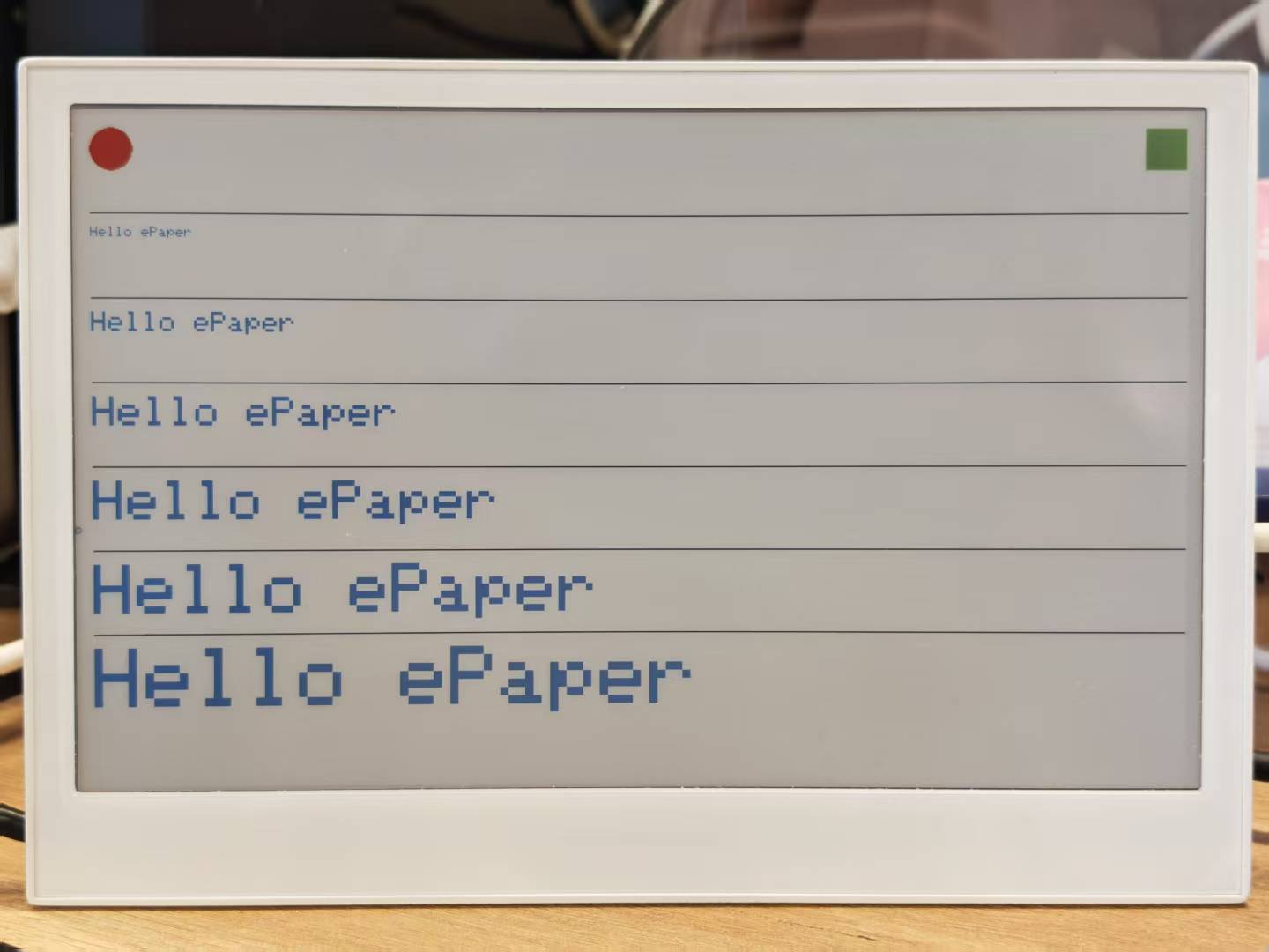
Paso 5. Sube el sketch a tu reTerminal E1002. La pantalla mostrará gráficos en color que demuestran las capacidades de color completo de la pantalla ePaper.
Programación de reTerminal E1003 (ePaper de 10,3 pulgadas)
Sigue el mismo flujo de trabajo usando la biblioteca Seeed_GFX para configurar y controlar la pantalla ePaper en el reTerminal E1003.
Paso 1. Abre un sketch de ejemplo de la biblioteca Seeed_GFX: File > Examples > Seeed_GFX > ePaper > Basic > HelloWorld
Paso 2. Habilita OPI PSRAM en el IDE de Arduino: Tools > PSRAM > OPI PSRAM
Paso 3. Crea un nuevo archivo llamado driver.h en la misma carpeta que tu sketch.
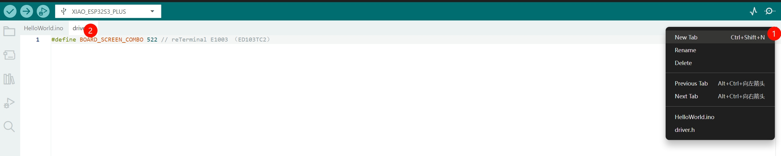
Paso 4. Copia el código de configuración generado y pégalo en el archivo driver.h para el E1003.
#define BOARD_SCREEN_COMBO 522 // reTerminal E1003 (ED103TC2)
Paso 5. Sube el sketch a tu reTerminal E1003 para verificar primitivas de dibujo, renderizado de texto y comportamientos de refresco de pantalla completa.
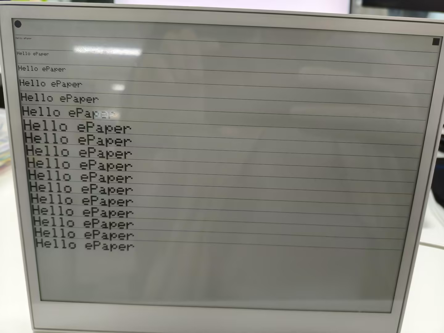
Programación de reTerminal E1004 (ePaper a todo color de 13,3 pulgadas)
Usa la biblioteca Seeed_GFX para configurar y controlar la pantalla ePaper a todo color E Ink® Spectra™ 6 en el reTerminal E1004.
Paso 1. Abre el sketch de ejemplo en color de la biblioteca Seeed_GFX: File > Examples > Seeed_GFX > ePaper > Basic > HelloWorld
Paso 2. Habilita OPI PSRAM en el IDE de Arduino: Tools > PSRAM > OPI PSRAM
Paso 3. Crea un nuevo archivo llamado driver.h en la misma carpeta que tu sketch.
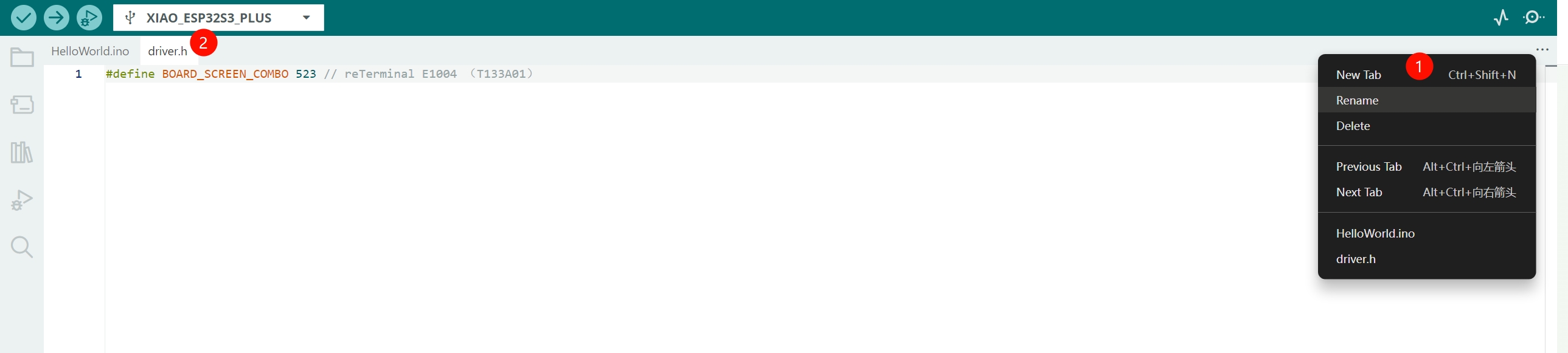
Paso 4. Copia el código de configuración generado y pégalo en el archivo driver.h para el E1004.
#define BOARD_SCREEN_COMBO 523 // reTerminal E1004 (T133A01)
Paso 5. Sube el sketch a tu reTerminal E1004 para verificar el renderizado de color, primitivas de dibujo, renderizado de texto y comportamientos de refresco de pantalla completa.
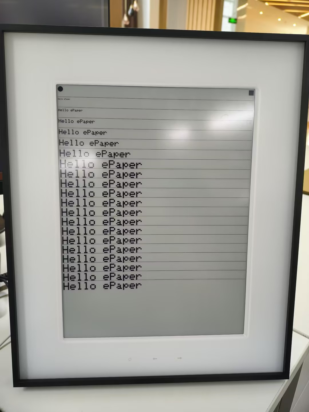
Escala de grises multinivel con Seeed_GFX
Los sketches de Hello World anteriores son intencionalmente mínimos para que quepan en todos los modelos. Los paneles monocromos en E1001 y E1003 en realidad admiten escala de grises multinivel además del simple blanco y negro: 4 niveles en E1001 y 16 niveles en E1003, y Seeed_GFX expone ambos modos mediante epaper.initGrayMode(...) más un conjunto de constantes de paleta TFT_GRAY_*. Los dos ejemplos siguientes recorren cada uno.
- E1001 — 4-Level Grayscale
- E1003 — 16-Level Grayscale
Escala de grises de 4 niveles en reTerminal E1001
El panel monocromo de 7,5" del reTerminal E1001 puede representar 4 niveles de escala de grises en lugar de solo blanco y negro. Seeed_GFX expone esto mediante epaper.initGrayMode(GRAY_LEVEL4) y cuatro constantes de paleta:
| Constant | Rendered Shade |
|---|---|
TFT_GRAY_0 | Black |
TFT_GRAY_1 | Dark gray |
TFT_GRAY_2 | Light gray |
TFT_GRAY_3 | White |
El siguiente ejemplo primero pinta cuatro franjas horizontales — una por nivel de gris — para que puedas verificar visualmente la paleta, y luego copia un mapa de bits en escala de grises de 800×480 en la pantalla. La biblioteca Seeed_GFX ya incluye esto como un ejemplo listo para flashear, incluyendo el image.h preconvertido, por lo que no necesitas generar tú mismo ningún dato de mapa de bits.
Paso 1. Abre el sketch de ejemplo de la biblioteca Seeed_GFX: File > Examples > Seeed_GFX > ePaper > Gray > GrayLevel4. El sketch y su archivo image.h asociado se abrirán en el editor.
Paso 2. Habilita OPI PSRAM en el IDE de Arduino: Tools > PSRAM > OPI PSRAM.
Paso 3. Añade un archivo driver.h junto al ejemplo (mismo flujo de trabajo que el Hello World) y selecciona la combinación de placa–pantalla E1001:
#define BOARD_SCREEN_COMBO 520 // reTerminal E1001 (UC8179)
Paso 4. Sube el sketch. La pantalla primero muestra cuatro franjas en escala de grises — negro en la parte superior, luego gris oscuro, gris claro y blanco en la parte inferior — y luego se limpia y renderiza el mapa de bits desde image.h.
Como referencia, el sketch de ejemplo se ve así:
/*
 * 4-Level Grayscale demo for reTerminal E1001
 * (Seeed_GFX/examples/ePaper/Gray/Shape/Shape.ino)
 *
 * The 7.5" monochrome panel supports 4 gray levels:
 *   TFT_GRAY_0  black
 *   TFT_GRAY_1  dark gray
 *   TFT_GRAY_2  light gray
 *   TFT_GRAY_3  white
 */
#include "TFT_eSPI.h"
#include "image.h"

#ifdef EPAPER_ENABLE  // Defined when an ePaper combo is selected in driver.h
EPaper epaper;
#endif

void setup() {
#ifdef EPAPER_ENABLE
  epaper.begin();
  epaper.fillScreen(TFT_WHITE);
  epaper.update();
  epaper.initGrayMode(GRAY_LEVEL4);

  // Draw four horizontal stripes, one per gray level
  epaper.fillRect(0, 0,                       epaper.width(), epaper.height() / 4, TFT_GRAY_0);
  epaper.fillRect(0, epaper.height() * 1 / 4, epaper.width(), epaper.height() / 4, TFT_GRAY_1);
  epaper.fillRect(0, epaper.height() * 2 / 4, epaper.width(), epaper.height() / 4, TFT_GRAY_2);
  epaper.fillRect(0, epaper.height() * 3 / 4, epaper.width(), epaper.height() / 4, TFT_GRAY_3);
  epaper.update();

  // Then clear and show a 800x480 grayscale bitmap from image.h
  epaper.fillScreen(TFT_GRAY_3);
  epaper.pushImage(0, 0, 800, 480, (uint16_t *)L4_GRAY);
  epaper.update();
#endif
}

void loop() {
  // Nothing to do — ePaper holds the last frame without power
}
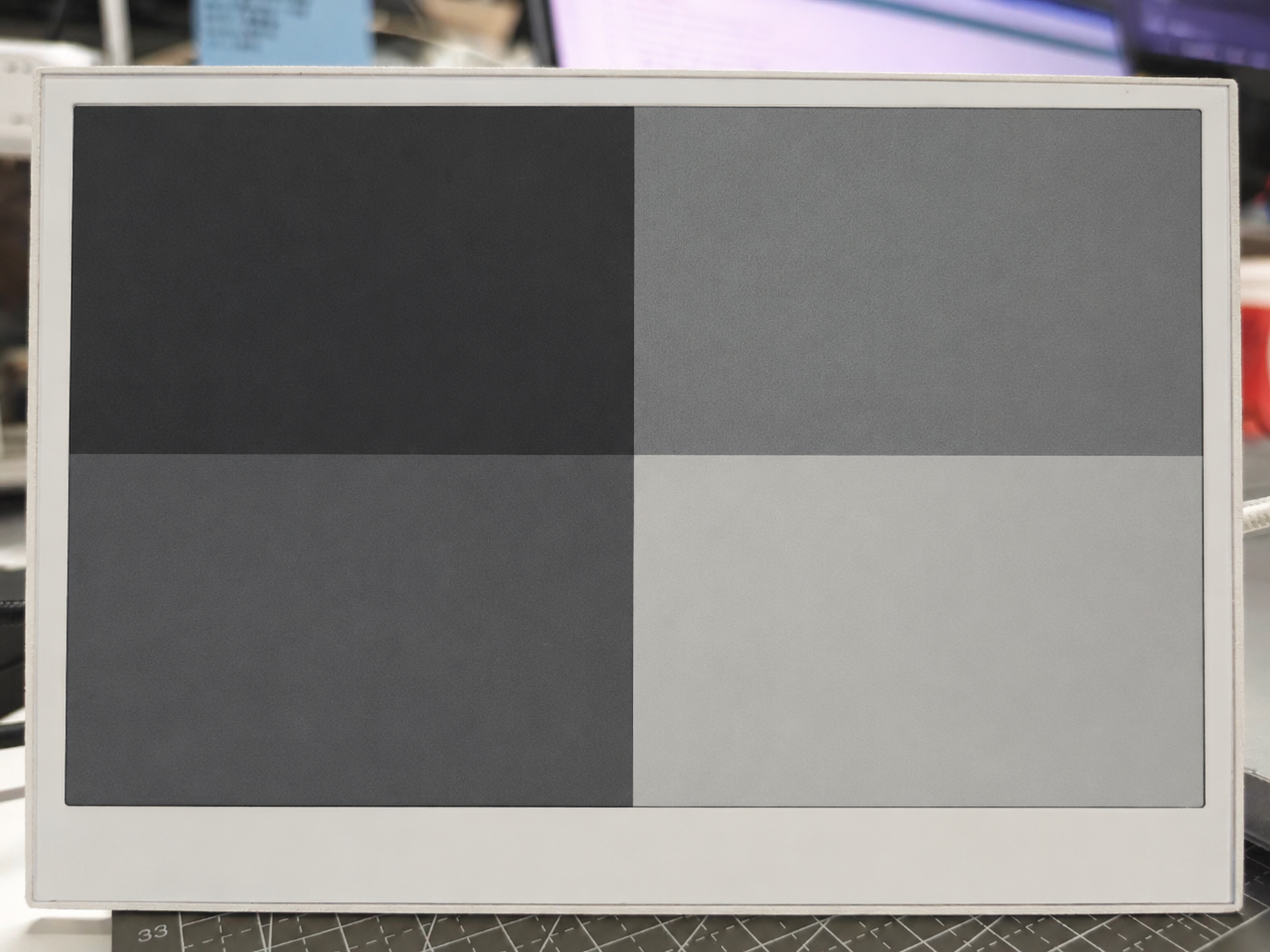
El array L4_GRAY en image.h es simplemente un mapa de bits en escala de grises de 800×480 preconvertido a un array de C. Para sustituir tu propia imagen, regenera el array a partir de una fuente en escala de grises de 800×480 usando cualquier conversor estándar de "imagen a array de C" y reemplaza L4_GRAY en image.h. El sketch en sí no necesita cambiar.
La actualización en escala de grises de 4 niveles es aproximadamente 4 veces más lenta que una actualización en blanco y negro de 1 bit porque el controlador lleva cada píxel a través de cuatro tensiones objetivo en lugar de dos. Úsala para contenido estático como fotos, ilustraciones o paneles con muchos detalles, y mantente en el modo estándar de 1 bit para actualizaciones rápidas de la interfaz de usuario.
Escala de grises de 16 niveles en reTerminal E1003
El panel de 10,3" del reTerminal E1003 eleva el listón a 16 niveles de escala de grises con una resolución de 1404×1872. Seeed_GFX expone esto mediante epaper.initGrayMode(GRAY_LEVEL16) y dieciséis constantes de paleta desde TFT_GRAY_0 (negro) hasta TFT_GRAY_15 (blanco):
| Constant | Rendered Shade |
|---|---|
TFT_GRAY_0 | Negro |
TFT_GRAY_1 … TFT_GRAY_14 | 14 grises intermedios (del más oscuro → al más claro) |
TFT_GRAY_15 | Blanco |
El siguiente ejemplo pinta 16 bandas horizontales — una por nivel de gris — para que puedas verificar visualmente la paleta completa en el panel. La biblioteca Seeed_GFX ya incluye esto como un ejemplo listo para flashear, con el driver.h correspondiente preconfigurado para la E1003, por lo que no necesitas cablear nada manualmente.
Paso 1. Abre el sketch de ejemplo de la biblioteca Seeed_GFX: File > Examples > Seeed_GFX > ePaper > Gray > GrayLevel16. El sketch se abre junto con su driver.h incluido (ya configurado como BOARD_SCREEN_COMBO 522 para el panel E1003 ED103TC2), por lo que no deberías necesitar editarlo.
Paso 2. Habilita OPI PSRAM en el IDE de Arduino: Tools > PSRAM > OPI PSRAM.
Paso 3. Sube el sketch. La pantalla muestra 16 bandas horizontales en escala de grises, desde negro puro en la parte superior hasta blanco puro en la parte inferior.
Como referencia, el sketch de ejemplo se ve así:
/* This is a 4-color electronic ink screen, but in GRAY_LEVEL16 mode
   it can render 16 levels of gray (TFT_GRAY_0 ~ TFT_GRAY_15).

   TFT_GRAY_0   -> black
   ...
   TFT_GRAY_15  -> white
*/

#include "TFT_eSPI.h"
#include "image.h"

#ifdef EPAPER_ENABLE  // Only compile this code if EPAPER_ENABLE is defined in User_Setup.h
EPaper epaper;
#endif

void setup()
{
#ifdef EPAPER_ENABLE
  epaper.begin();
  epaper.fillScreen(TFT_WHITE);
  epaper.update();                       // refresh once to clear the screen
  epaper.initGrayMode(GRAY_LEVEL16);     // switch to 16-level gray mode

  // 16 levels of gray: TFT_GRAY_0 (black) ... TFT_GRAY_15 (white)
  const uint8_t grayLevels[16] = {
    TFT_GRAY_0,  TFT_GRAY_1,  TFT_GRAY_2,  TFT_GRAY_3,
    TFT_GRAY_4,  TFT_GRAY_5,  TFT_GRAY_6,  TFT_GRAY_7,
    TFT_GRAY_8,  TFT_GRAY_9,  TFT_GRAY_10, TFT_GRAY_11,
    TFT_GRAY_12, TFT_GRAY_13, TFT_GRAY_14, TFT_GRAY_15
  };

  int16_t screenW = epaper.width();
  int16_t screenH = epaper.height();
  int16_t bandH   = screenH / 16;        // height of each gray band

  for (uint8_t i = 0; i < 16; i++) {
    int16_t y = i * bandH;
    // Make the last band absorb any remainder pixels so the screen is fully covered
    int16_t h = (i == 15) ? (screenH - y) : bandH;
    epaper.fillRect(0, y, screenW, h, grayLevels[i]);
  }

  epaper.update();
#endif
}

void loop()
{
  // Nothing to do — ePaper holds the last frame without power
}
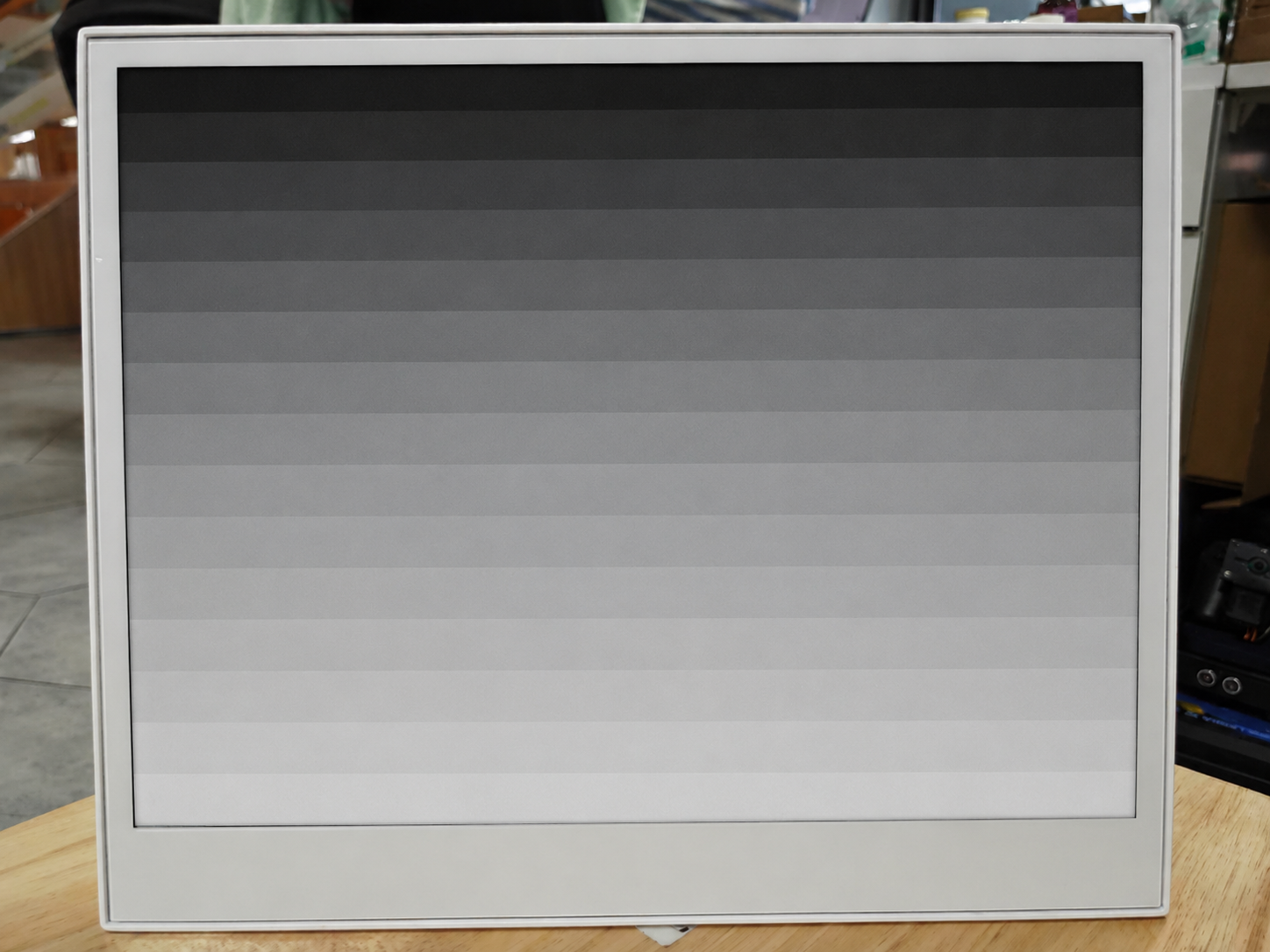
La escala de grises de 16 niveles es el modo de refresco más lento en este panel porque cada píxel tiene que estabilizarse a través de 16 niveles de voltaje en lugar de 2. Úsalo para contenido estático tipo foto y paneles de control, y vuelve al modo estándar de 1 bit para actualizaciones rápidas de la interfaz.
Uso de la biblioteca GxEPD2
Además de Seeed_GFX, también puedes usar la biblioteca GxEPD2 para controlar la pantalla de tinta electrónica del reTerminal. Seeed ha hecho un fork de la popular biblioteca GxEPD2 y ha añadido soporte dedicado para la serie reTerminal E10xx, lo que la convierte en la opción recomendada para los usuarios de reTerminal.
Instalar la biblioteca Seeed_GxEPD2
Para usar esta biblioteca con productos reTerminal, necesitas instalar Seeed_GxEPD2, el fork personalizado de Seeed adaptado específicamente para la serie reTerminal E10xx.
Paso 1. Ve al repositorio de GitHub de Seeed_GxEPD2. Haz clic en el botón "Code" y luego selecciona "Download ZIP" para guardar la biblioteca en tu ordenador.
Paso 2. En el IDE de Arduino, instala la biblioteca desde el archivo descargado. Ve a Sketch > Include Library > Add .ZIP Library... y selecciona el archivo ZIP que acabas de descargar.
Paso 3. La biblioteca Seeed_GxEPD2 requiere la Adafruit GFX Library para funcionar, que también debes instalar. La forma más sencilla de hacerlo es a través del Library Manager: ve a Tools > Manage Libraries..., busca "Adafruit GFX Library" y haz clic en "Install".
Seeed_GxEPD2 es el fork personalizado de Seeed de la biblioteca original GxEPD2, con controladores y optimizaciones dedicados para la serie reTerminal E10xx. Recomendamos encarecidamente usar este fork en lugar de la biblioteca original para garantizar la compatibilidad total con tu dispositivo reTerminal.
- reTerminal E1001
- reTerminal E1002
- reTerminal E1003
- reTerminal E1004
Programar reTerminal E1001 (pantalla en blanco y negro de 7,5")
El reTerminal E1001 incorpora una pantalla de tinta electrónica en blanco y negro de 7,5" (800×480, panel GDEY075T7, controlador UC8179). El siguiente ejemplo muestra varias pantallas, incluyendo una de inicio, información del sistema, tipografía, geometría, patrones y un diseño de panel de control.
Después de instalar la biblioteca Seeed_GxEPD2, puedes encontrar este ejemplo en el IDE de Arduino mediante File > Examples > Seeed_GxEPD2 > GxEPD2_reTerminal_E1001, o localizarlo manualmente en Seeed_GxEPD2/examples/GxEPD2_reTerminal_E1001/GxEPD2_reTerminal_E1001.ino.Haz clic aquí para ver el código completo
#include <SPI.h>
#include <GxEPD2_BW.h>
#include <Fonts/FreeMonoBold9pt7b.h>
#include <Fonts/FreeMonoBold12pt7b.h>
#include <Fonts/FreeSansBold24pt7b.h>
#include <Fonts/FreeSansBold18pt7b.h>
#include <Fonts/FreeSansBold12pt7b.h>
#include <Fonts/FreeSans9pt7b.h>
#include <Fonts/FreeMono9pt7b.h>

// ===== Pin mapping =====
#define EPD_SCK_PIN   7
#define EPD_MOSI_PIN  9
#define EPD_CS_PIN    10
#define EPD_DC_PIN    11
#define EPD_RES_PIN   12
#define EPD_BUSY_PIN  13

SPIClass hspi(HSPI);

// ===== Display: 7.5" B&W 800x480 =====
#define MAX_DISPLAY_BUFFER_SIZE 16000u
#define MAX_HEIGHT(EPD) \
    (EPD::HEIGHT <= MAX_DISPLAY_BUFFER_SIZE / (EPD::WIDTH / 8) \
         ? EPD::HEIGHT \
         : MAX_DISPLAY_BUFFER_SIZE / (EPD::WIDTH / 8))

GxEPD2_BW<GxEPD2_750_GDEY075T7, MAX_HEIGHT(GxEPD2_750_GDEY075T7)>
    display(GxEPD2_750_GDEY075T7(EPD_CS_PIN, EPD_DC_PIN, EPD_RES_PIN, EPD_BUSY_PIN));

void setup()
{
  Serial.begin(115200);
  delay(200);
  Serial.println(F("[E1001] GxEPD2 reTerminal E1001 Demo (7.5\" B&W)"));

  pinMode(EPD_RES_PIN, OUTPUT);
  pinMode(EPD_DC_PIN,  OUTPUT);
  pinMode(EPD_CS_PIN,  OUTPUT);

  hspi.begin(EPD_SCK_PIN, -1, EPD_MOSI_PIN, -1);
  display.epd2.selectSPI(hspi, SPISettings(2000000, MSBFIRST, SPI_MODE0));
  display.init(0);

  Serial.println(F("[E1001] Screen 1: Splash"));
  showSplashScreen();
  delay(3000);

  Serial.println(F("[E1001] Screen 2: System Info"));
  showSystemInfo();
  delay(3000);

  Serial.println(F("[E1001] Screen 3: Typography"));
  showTypographyDemo();
  delay(3000);

  Serial.println(F("[E1001] Screen 4: Geometry"));
  showGeometryDemo();
  delay(3000);

  Serial.println(F("[E1001] Screen 5: Patterns"));
  showPatternDemo();
  delay(3000);

  Serial.println(F("[E1001] Screen 6: Dashboard"));
  showDashboardDemo();

  Serial.println(F("[E1001] Demo complete. Hibernating."));
  delay(2000);
  display.hibernate();
}

void loop() {}

// =====================================================================
void drawCenteredText(const char* text, int16_t y, const GFXfont* font)
{
  display.setFont(font);
  int16_t tbx, tby; uint16_t tbw, tbh;
  display.getTextBounds(text, 0, 0, &tbx, &tby, &tbw, &tbh);
  display.setCursor((display.width() - tbw) / 2 - tbx, y);
  display.print(text);
}

// =====================================================================
// Screen 1: Splash
// =====================================================================
void showSplashScreen()
{
  const uint16_t W = display.width();
  const uint16_t H = display.height();
  display.setRotation(0);
  display.setFullWindow();
  display.firstPage();
  do {
    display.fillScreen(GxEPD_WHITE);
    display.drawRect(10, 10, W - 20, H - 20, GxEPD_BLACK);
    display.drawRect(14, 14, W - 28, H - 28, GxEPD_BLACK);

    display.setTextColor(GxEPD_BLACK);
    drawCenteredText("reTerminal E1001", H / 2 - 60, &FreeSansBold24pt7b);
    drawCenteredText("7.5\" e-Paper Display", H / 2 - 10, &FreeSansBold12pt7b);
    display.drawFastHLine(W / 4, H / 2 + 10, W / 2, GxEPD_BLACK);
    drawCenteredText("GxEPD2 + UC8179 Driver Demo", H / 2 + 45, &FreeSansBold12pt7b);
    drawCenteredText("800 x 480 pixels | Black & White", H / 2 + 75, &FreeSans9pt7b);
    drawCenteredText("Seeed Studio x GxEPD2", H - 40, &FreeSans9pt7b);
  } while (display.nextPage());
}

// =====================================================================
// Screen 2: System Info
// =====================================================================
void showSystemInfo()
{
  const uint16_t W = display.width();
  const uint16_t H = display.height();
  display.setRotation(0);
  display.setFullWindow();
  display.firstPage();
  do {
    display.fillScreen(GxEPD_WHITE);
    display.fillRect(0, 0, W, 40, GxEPD_BLACK);
    display.setTextColor(GxEPD_WHITE);
    drawCenteredText("System Information", 30, &FreeSansBold12pt7b);

    display.setTextColor(GxEPD_BLACK);
    display.setFont(&FreeMonoBold9pt7b);

    const char* labels[] = {"MCU", "Display", "Panel", "Controller", "Interface", "Color Depth"};
    char chipBuf[48];
    snprintf(chipBuf, sizeof(chipBuf), "ESP32-S3 @ %lu MHz", (unsigned long)ESP.getCpuFreqMHz());
    const char* values[] = {chipBuf, "800 x 480", "GDEY075T7", "UC8179", "SPI (HSPI) @ 2MHz", "B&W (1-bit)"};

    int y = 95;
    for (int i = 0; i < 6; i++) {
      display.setCursor(50, y);
      display.print(labels[i]);
      display.setCursor(250, y);
      display.print(": ");
      display.print(values[i]);
      y += 48;
      if (i < 5) display.drawFastHLine(50, y - 18, W - 100, GxEPD_BLACK);
    }

    display.drawFastHLine(30, H - 40, W - 60, GxEPD_BLACK);
    drawCenteredText("reTerminal E1001 | GxEPD2 Demo", H - 20, &FreeSans9pt7b);
  } while (display.nextPage());
}

// =====================================================================
// Screen 3: Typography
// =====================================================================
void showTypographyDemo()
{
  const uint16_t W = display.width();
  const uint16_t H = display.height();
  display.setRotation(0);
  display.setFullWindow();
  display.firstPage();
  do {
    display.fillScreen(GxEPD_WHITE);
    display.fillRect(0, 0, W, 40, GxEPD_BLACK);
    display.setTextColor(GxEPD_WHITE);
    drawCenteredText("Typography Demo", 30, &FreeSansBold12pt7b);

    display.setTextColor(GxEPD_BLACK);
    int y = 85, x = 40;

    display.setFont(&FreeSansBold24pt7b);
    display.setCursor(x, y); display.print("Sans Bold 24pt");
    y += 65;

    display.setFont(&FreeSansBold18pt7b);
    display.setCursor(x, y); display.print("Sans Bold 18pt");
    y += 50;

    display.setFont(&FreeSansBold12pt7b);
    display.setCursor(x, y); display.print("Sans Bold 12pt - Clean and Modern");
    y += 42;

    display.setFont(&FreeSans9pt7b);
    display.setCursor(x, y); display.print("Sans 9pt - Body text for dense info display.");
    y += 40;

    display.drawFastHLine(x, y, W - 80, GxEPD_BLACK);
    y += 25;

    display.setFont(&FreeMonoBold12pt7b);
    display.setCursor(x, y); display.print("Mono Bold 12pt");
    y += 38;

    display.setFont(&FreeMono9pt7b);
    display.setCursor(x, y); display.print("Mono 9pt: 0123456789 ABCDEF");
    y += 38;

    display.setFont(&FreeSansBold18pt7b);
    display.setCursor(x, y); display.print("0 1 2 3 4 5 6 7 8 9");

    drawCenteredText("Multiple fonts supported", H - 20, &FreeSans9pt7b);
  } while (display.nextPage());
}

// =====================================================================
// Screen 4: Geometry
// =====================================================================
void showGeometryDemo()
{
  const uint16_t W = display.width();
  const uint16_t H = display.height();
  display.setRotation(0);
  display.setFullWindow();
  display.firstPage();
  do {
    display.fillScreen(GxEPD_WHITE);
    display.fillRect(0, 0, W, 40, GxEPD_BLACK);
    display.setTextColor(GxEPD_WHITE);
    drawCenteredText("Geometry Demo", 30, &FreeSansBold12pt7b);
    display.setTextColor(GxEPD_BLACK);

    // Rectangles
    for (int i = 0; i < 4; i++)
      display.drawRect(40 + i * 80, 60, 60, 50, GxEPD_BLACK);
    display.fillRect(40 + 4 * 80, 60, 60, 50, GxEPD_BLACK);

    // Circles
    for (int i = 0; i < 4; i++)
      display.drawCircle(70 + i * 90, 170, 25 + i * 3, GxEPD_BLACK);
    for (int i = 0; i < 3; i++)
      display.fillCircle(70 + (i + 4) * 90, 170, 25 + i * 3, GxEPD_BLACK);

    // Triangles
    for (int i = 0; i < 5; i++) {
      int tx = 50 + i * 120, sz = 40 + i * 5;
      display.drawTriangle(tx, 270 + sz, tx + sz / 2, 270, tx + sz, 270 + sz, GxEPD_BLACK);
    }

    // Fan of lines
    int fcx = 150, fcy = 410;
    for (int a = 0; a < 180; a += 12) {
      float rad = a * 3.14159f / 180.0f;
      display.drawLine(fcx, fcy, fcx + (int)(60 * cosf(rad)), fcy - (int)(60 * sinf(rad)), GxEPD_BLACK);
    }

    // Concentric circles
    for (int r = 8; r <= 56; r += 8)
      display.drawCircle(400, 400, r, GxEPD_BLACK);

    // Rounded rects
    for (int i = 0; i < 3; i++)
      display.drawRoundRect(550 + i * 8, 340 + i * 8, 120 - i * 16, 100 - i * 16, 8 + i * 4, GxEPD_BLACK);

    drawCenteredText("Adafruit GFX primitives on 7.5\" e-Paper", H - 15, &FreeSans9pt7b);
  } while (display.nextPage());
}

// =====================================================================
// Screen 5: Patterns
// =====================================================================
void showPatternDemo()
{
  const uint16_t W = display.width();
  const uint16_t H = display.height();
  display.setRotation(0);
  display.setFullWindow();
  display.firstPage();
  do {
    display.fillScreen(GxEPD_WHITE);
    display.fillRect(0, 0, W, 40, GxEPD_BLACK);
    display.setTextColor(GxEPD_WHITE);
    drawCenteredText("Pattern Demo", 30, &FreeSansBold12pt7b);
    display.setTextColor(GxEPD_BLACK);
    display.setFont(&FreeSans9pt7b);

    int bx = 30, by = 55, bw = 150, bh = 150, gap = 30;

    // Checkerboard
    display.setCursor(bx + 25, by + 15); display.print("Checker");
    by += 20;
    for (int py = 0; py < bh / 12; py++)
      for (int px = 0; px < bw / 12; px++)
        if ((px + py) & 1)
          display.fillRect(bx + px * 12, by + py * 12, 12, 12, GxEPD_BLACK);

    // H-stripes
    int bx2 = bx + bw + gap; int by2 = by - 20;
    display.setCursor(bx2 + 25, by2 + 15); display.print("H-Stripes");
    by2 += 20;
    for (int py = 0; py < bh; py += 8)
      if ((py / 8) & 1)
        display.fillRect(bx2, by2 + py, bw, 8, GxEPD_BLACK);

    // V-stripes
    int bx3 = bx2 + bw + gap; int by3 = by2 - 20;
    display.setCursor(bx3 + 25, by3 + 15); display.print("V-Stripes");
    by3 += 20;
    for (int px = 0; px < bw; px += 8)
      if ((px / 8) & 1)
        display.fillRect(bx3 + px, by3, 8, bh, GxEPD_BLACK);

    // Dot grid
    int bx4 = bx3 + bw + gap; int by4 = by3 - 20;
    display.setCursor(bx4 + 30, by4 + 15); display.print("Dot Grid");
    by4 += 20;
    for (int py = 0; py < bh; py += 12)
      for (int px = 0; px < bw; px += 12)
        display.fillCircle(bx4 + px + 6, by4 + py + 6, 3, GxEPD_BLACK);

    // Dither gradient (bottom)
    int gx = 30, gy = 310, gw = W - 60, gh = 120;
    display.setFont(&FreeSans9pt7b);
    display.setCursor(gx, gy - 5); display.print("Dither Gradient:");
    display.drawRect(gx, gy, gw, gh, GxEPD_BLACK);
    for (int py = 0; py < gh; py++)
      for (int px = 0; px < gw; px++) {
        int density = (px * 255) / gw;
        if ((((px * 7 + py * 13) ^ (px * py)) & 0xFF) < density)
          display.drawPixel(gx + px, gy + py, GxEPD_BLACK);
      }

    drawCenteredText("Fill patterns and dithering", H - 15, &FreeSans9pt7b);
  } while (display.nextPage());
}

// =====================================================================
// Screen 6: Dashboard
// =====================================================================
void drawCard(int x, int y, int w, int h, const char* title, const char* value, const char* unit)
{
  display.drawRoundRect(x, y, w, h, 6, GxEPD_BLACK);
  display.fillRoundRect(x + 2, y + 2, w - 4, 26, 4, GxEPD_BLACK);
  display.setTextColor(GxEPD_WHITE);
  display.setFont(&FreeSansBold12pt7b);
  int16_t tbx, tby; uint16_t tbw, tbh;
  display.getTextBounds(title, 0, 0, &tbx, &tby, &tbw, &tbh);
  display.setCursor(x + (w - tbw) / 2 - tbx, y + 22);
  display.print(title);

  display.setTextColor(GxEPD_BLACK);
  display.setFont(&FreeSansBold18pt7b);
  display.getTextBounds(value, 0, 0, &tbx, &tby, &tbw, &tbh);
  display.setCursor(x + (w - tbw) / 2 - tbx, y + h / 2 + 12);
  display.print(value);

  display.setFont(&FreeSans9pt7b);
  display.getTextBounds(unit, 0, 0, &tbx, &tby, &tbw, &tbh);
  display.setCursor(x + (w - tbw) / 2 - tbx, y + h - 10);
  display.print(unit);
}

void showDashboardDemo()
{
  const uint16_t W = display.width();
  const uint16_t H = display.height();
  display.setRotation(0);
  display.setFullWindow();
  display.firstPage();
  do {
    display.fillScreen(GxEPD_WHITE);
    display.fillRect(0, 0, W, 40, GxEPD_BLACK);
    display.setTextColor(GxEPD_WHITE);
    drawCenteredText("Dashboard Demo", 30, &FreeSansBold12pt7b);
    display.setTextColor(GxEPD_BLACK);

    int cw = 170, ch = 130, gap = 20;
    int sx = (W - 4 * cw - 3 * gap) / 2;
    int row1Y = 60;

    char uptBuf[16]; snprintf(uptBuf, sizeof(uptBuf), "%lu", millis() / 1000);
    char heapBuf[16]; snprintf(heapBuf, sizeof(heapBuf), "%lu", (unsigned long)(ESP.getFreeHeap() / 1024));

    drawCard(sx,                       row1Y, cw, ch, "Temp",     "23.5",  "Celsius");
    drawCard(sx + cw + gap,            row1Y, cw, ch, "Humidity", "65",    "% RH");
    drawCard(sx + 2 * (cw + gap),      row1Y, cw, ch, "Heap",    heapBuf, "kB free");
    drawCard(sx + 3 * (cw + gap),      row1Y, cw, ch, "Uptime",  uptBuf,  "seconds");

    // Log area
    int logY = row1Y + ch + 20;
    display.drawRoundRect(sx, logY, W - 2 * sx, 200, 6, GxEPD_BLACK);
    display.fillRoundRect(sx + 2, logY + 2, W - 2 * sx - 4, 26, 4, GxEPD_BLACK);
    display.setTextColor(GxEPD_WHITE);
    display.setFont(&FreeSansBold12pt7b);
    display.setCursor(sx + 15, logY + 22);
    display.print("Activity Log");
    display.setTextColor(GxEPD_BLACK);
    display.setFont(&FreeMono9pt7b);

    const char* logs[] = {
      "[00:01] System boot - ESP32-S3",
      "[00:02] Panel: GDEY075T7 800x480",
      "[00:03] UC8179 controller ready",
      "[00:04] SPI @ 2MHz (HSPI)",
      "[00:05] Demo sequence started",
    };
    int ly = logY + 50;
    for (int i = 0; i < 5; i++) {
      display.setCursor(sx + 15, ly);
      display.print(logs[i]);
      ly += 28;
    }

    // Progress bar
    int barY = logY + 210;
    display.setFont(&FreeSansBold12pt7b);
    display.setCursor(sx, barY + 15);
    display.print("Progress:");
    int barX = sx + 170, barW = W - 2 * sx - 180, barH = 20;
    display.drawRect(barX, barY, barW, barH, GxEPD_BLACK);
    display.fillRect(barX + 2, barY + 2, barW - 4, barH - 4, GxEPD_BLACK);
    display.setFont(&FreeSans9pt7b);
    display.setCursor(barX + barW + 8, barY + 14);
    display.print("100%");

    drawCenteredText("E-paper: zero power to maintain image", H - 15, &FreeSans9pt7b);
  } while (display.nextPage());
}
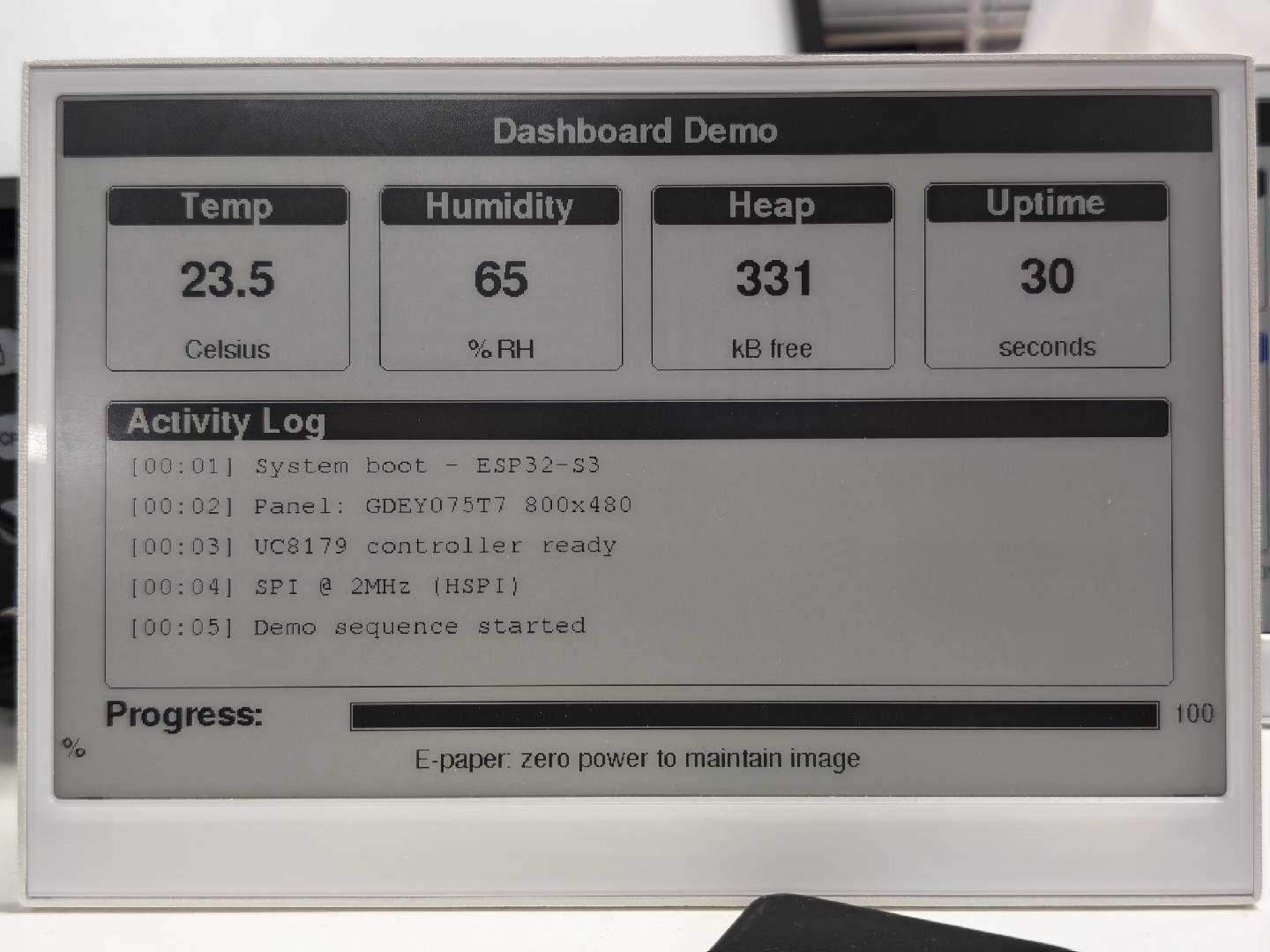
La siguiente figura muestra el efecto de visualización real del ejemplo E1001:
Programación de reTerminal E1002 (pantalla de 7,3" y 6 colores)
El reTerminal E1002 incorpora una pantalla de tinta electrónica de 7,3" y 6 colores (800×480, panel GDEP073E01, controlador ED2208). Es compatible con negro, blanco, rojo, verde, azul y amarillo. El siguiente ejemplo demuestra la representación de color a través de múltiples pantallas.
Después de instalar la biblioteca Seeed_GxEPD2, puedes encontrar este ejemplo en el IDE de Arduino a través de File > Examples > Seeed_GxEPD2 > GxEPD2_reTerminal_E1002, o localizarlo manualmente en Seeed_GxEPD2/examples/GxEPD2_reTerminal_E1002/GxEPD2_reTerminal_E1002.ino.Haz clic aquí para ver el código completo
#include <SPI.h>
#include <GxEPD2_7C.h>
#include <Fonts/FreeMonoBold9pt7b.h>
#include <Fonts/FreeMonoBold12pt7b.h>
#include <Fonts/FreeSansBold24pt7b.h>
#include <Fonts/FreeSansBold18pt7b.h>
#include <Fonts/FreeSansBold12pt7b.h>
#include <Fonts/FreeSans9pt7b.h>
#include <Fonts/FreeMono9pt7b.h>

// ===== Pin mapping =====
#define EPD_SCK_PIN   7
#define EPD_MOSI_PIN  9
#define EPD_CS_PIN    10
#define EPD_DC_PIN    11
#define EPD_RES_PIN   12
#define EPD_BUSY_PIN  13

SPIClass hspi(HSPI);

// ===== Display: 7.3" 6-Color 800x480 =====
#define MAX_DISPLAY_BUFFER_SIZE 16000u
#define MAX_HEIGHT(EPD) \
    (EPD::HEIGHT <= (MAX_DISPLAY_BUFFER_SIZE) / (EPD::WIDTH / 2) \
         ? EPD::HEIGHT \
         : (MAX_DISPLAY_BUFFER_SIZE) / (EPD::WIDTH / 2))

GxEPD2_7C<GxEPD2_730c_GDEP073E01, MAX_HEIGHT(GxEPD2_730c_GDEP073E01)>
    display(GxEPD2_730c_GDEP073E01(EPD_CS_PIN, EPD_DC_PIN, EPD_RES_PIN, EPD_BUSY_PIN));

// Convenience color names for the GDEP073E01 6-color palette.
// Note: GxEPD_ORANGE is intentionally NOT used — this panel has no orange,
// and the driver would silently map it to the closest available color
// (usually yellow or red), producing wrong-looking renders.
#define C_BLACK   GxEPD_BLACK
#define C_WHITE   GxEPD_WHITE
#define C_GREEN   GxEPD_GREEN
#define C_BLUE    GxEPD_BLUE
#define C_RED     GxEPD_RED
#define C_YELLOW  GxEPD_YELLOW

void setup()
{
  Serial.begin(115200);
  delay(200);
  Serial.println(F("[E1002] GxEPD2 reTerminal E1002 Demo (7.3\" 6-Color)"));

  pinMode(EPD_RES_PIN, OUTPUT);
  pinMode(EPD_DC_PIN,  OUTPUT);
  pinMode(EPD_CS_PIN,  OUTPUT);

  hspi.begin(EPD_SCK_PIN, -1, EPD_MOSI_PIN, -1);
  display.epd2.selectSPI(hspi, SPISettings(2000000, MSBFIRST, SPI_MODE0));
  display.init(0);

  // E1002 is a 6-color panel. Each full refresh itself takes ~25-30s, and
  // we want each rendered page to stay visible for a good while before the
  // next refresh kicks in. Keep PAGE_HOLD_MS >= 60s.
  const uint32_t PAGE_HOLD_MS = 60000;

  Serial.println(F("[E1002] Screen 1: Splash"));
  showSplashScreen();
  delay(PAGE_HOLD_MS);

  Serial.println(F("[E1002] Screen 2: Color Palette"));
  showColorPalette();
  delay(PAGE_HOLD_MS);

  Serial.println(F("[E1002] Screen 3: Color Typography"));
  showColorTypography();
  delay(PAGE_HOLD_MS);

  Serial.println(F("[E1002] Screen 4: Color Geometry"));
  showColorGeometry();
  delay(PAGE_HOLD_MS);

  Serial.println(F("[E1002] Screen 5: Color Patterns"));
  showColorPatterns();
  delay(PAGE_HOLD_MS);

  Serial.println(F("[E1002] Screen 6: Dashboard"));
  showDashboard();
  delay(PAGE_HOLD_MS);

  Serial.println(F("[E1002] Demo complete. Hibernating."));
  display.hibernate();
}

void loop() {}

// =====================================================================
void drawCenteredText(const char* text, int16_t y, const GFXfont* font)
{
  display.setFont(font);
  int16_t tbx, tby; uint16_t tbw, tbh;
  display.getTextBounds(text, 0, 0, &tbx, &tby, &tbw, &tbh);
  display.setCursor((display.width() - tbw) / 2 - tbx, y);
  display.print(text);
}

// =====================================================================
// Screen 1: Splash
// =====================================================================
void showSplashScreen()
{
  const uint16_t W = display.width();
  const uint16_t H = display.height();
  display.setRotation(0);
  display.setFullWindow();
  display.firstPage();
  do {
    display.fillScreen(C_WHITE);

    // Colorful top stripe — 6 native colors
    int stripeH = 12, stripeY = 10;
    uint16_t colors[] = {C_RED, C_YELLOW, C_GREEN, C_BLUE, C_BLACK, C_RED};
    int stripeW = (W - 20) / 6;
    for (int i = 0; i < 6; i++)
      display.fillRect(10 + i * stripeW, stripeY, stripeW, stripeH, colors[i]);

    display.drawRect(10, 30, W - 20, H - 40, C_BLACK);

    display.setTextColor(C_BLACK);
    drawCenteredText("reTerminal E1002", H / 2 - 60, &FreeSansBold24pt7b);

    display.setTextColor(C_RED);
    drawCenteredText("7.3\" 6-Color e-Paper", H / 2 - 10, &FreeSansBold12pt7b);

    display.drawFastHLine(W / 4, H / 2 + 15, W / 2, C_BLUE);

    display.setTextColor(C_GREEN);
    drawCenteredText("GxEPD2 + GDEP073E01 Demo", H / 2 + 50, &FreeSansBold12pt7b);

    display.setTextColor(C_BLUE);
    drawCenteredText("800 x 480 | 6 Colors", H / 2 + 85, &FreeSans9pt7b);

    // Bottom colorful stripe (reversed order)
    uint16_t bottomColors[] = {C_BLUE, C_GREEN, C_YELLOW, C_RED, C_BLACK, C_BLUE};
    for (int i = 0; i < 6; i++)
      display.fillRect(10 + i * stripeW, H - 22, stripeW, stripeH, bottomColors[i]);

    display.setTextColor(C_BLACK);
    drawCenteredText("Seeed Studio x GxEPD2", H - 35, &FreeSans9pt7b);
  } while (display.nextPage());
}

// =====================================================================
// Screen 2: Color Palette
// =====================================================================
void showColorPalette()
{
  const uint16_t W = display.width();
  const uint16_t H = display.height();
  display.setRotation(0);
  display.setFullWindow();
  display.firstPage();
  do {
    display.fillScreen(C_WHITE);
    display.fillRect(0, 0, W, 40, C_BLACK);
    display.setTextColor(C_WHITE);
    drawCenteredText("6-Color Palette", 30, &FreeSansBold12pt7b);

    const uint16_t swatchColors[] = {C_BLACK, C_WHITE, C_RED, C_GREEN, C_BLUE, C_YELLOW};
    const char* names[] = {"Black", "White", "Red", "Green", "Blue", "Yellow"};
    int sw = 110, sh = 140, gap = 18;
    int sx = (W - 6 * sw - 5 * gap) / 2;
    int sy = 70;

    for (int i = 0; i < 6; i++) {
      int x = sx + i * (sw + gap);
      display.fillRoundRect(x, sy, sw, sh, 6, swatchColors[i]);
      display.drawRoundRect(x, sy, sw, sh, 6, C_BLACK);
      display.setFont(&FreeSansBold12pt7b);
      display.setTextColor(C_BLACK);
      int16_t tbx, tby; uint16_t tbw, tbh;
      display.getTextBounds(names[i], 0, 0, &tbx, &tby, &tbw, &tbh);
      display.setCursor(x + (sw - tbw) / 2 - tbx, sy + sh + 25);
      display.print(names[i]);
    }

    // Mixed-color row: circles on different backgrounds (5 combos)
    int row2Y = sy + sh + 60;
    display.setFont(&FreeSans9pt7b);
    display.setTextColor(C_BLACK);
    display.setCursor(sx, row2Y - 5);
    display.print("Color combinations:");

    int cx = sx + 40;
    uint16_t bgColors[] =  {C_RED,    C_GREEN, C_BLUE,   C_YELLOW, C_BLACK};
    uint16_t fgColors[] =  {C_YELLOW, C_RED,   C_YELLOW, C_BLUE,   C_RED};
    for (int i = 0; i < 5; i++) {
      int x = cx + i * 130;
      display.fillRoundRect(x, row2Y + 10, 80, 80, 8, bgColors[i]);
      display.fillCircle(x + 40, row2Y + 50, 25, fgColors[i]);
    }

    // Bottom row: colored bars as gradient (5 bars, no orange)
    int barY = row2Y + 110;
    display.setTextColor(C_BLACK);
    display.setCursor(sx, barY - 5);
    display.print("Full-width color bars:");
    uint16_t barColors[] = {C_RED, C_YELLOW, C_GREEN, C_BLUE, C_BLACK};
    int barH = 18;
    for (int i = 0; i < 5; i++)
      display.fillRect(sx, barY + 10 + i * (barH + 4), W - 2 * sx, barH, barColors[i]);

    drawCenteredText("All 6 native colors on the GDEP073E01 panel", H - 15, &FreeSans9pt7b);
  } while (display.nextPage());
}

// =====================================================================
// Screen 3: Color Typography
// =====================================================================
void showColorTypography()
{
  const uint16_t W = display.width();
  const uint16_t H = display.height();
  display.setRotation(0);
  display.setFullWindow();
  display.firstPage();
  do {
    display.fillScreen(C_WHITE);
    display.fillRect(0, 0, W, 40, C_BLUE);
    display.setTextColor(C_WHITE);
    drawCenteredText("Color Typography", 30, &FreeSansBold12pt7b);

    int y = 82, x = 40;

    display.setTextColor(C_BLACK);
    display.setFont(&FreeSansBold24pt7b);
    display.setCursor(x, y); display.print("Black");
    display.setTextColor(C_RED);
    display.setCursor(x + 200, y); display.print("Red");
    display.setTextColor(C_GREEN);
    display.setCursor(x + 340, y); display.print("Green");
    display.setTextColor(C_BLUE);
    display.setCursor(x + 530, y); display.print("Blue");
    y += 58;

    display.setTextColor(C_YELLOW);
    display.setFont(&FreeSansBold18pt7b);
    display.setCursor(x, y); display.print("Yellow text - warm and bright");
    y += 48;

    display.setTextColor(C_RED);
    display.setFont(&FreeSansBold18pt7b);
    display.setCursor(x, y); display.print("Red - emphasis and warnings");
    y += 52;

    display.drawFastHLine(x, y, W - 80, C_RED);
    y += 22;

    // Inverted: white text on color rectangles (4 combos)
    display.setFont(&FreeSansBold12pt7b);
    int bx = x, bw = 220, bh = 40, bgap = 16;
    uint16_t tColors[] = {C_RED, C_GREEN, C_BLUE, C_BLACK};
    const char* labels[] = {"White on Red", "White on Green", "White on Blue", "White on Black"};
    for (int i = 0; i < 4; i++) {
      int by2 = y + i * (bh + bgap);
      display.fillRoundRect(bx, by2, bw, bh, 4, tColors[i]);
      display.setTextColor(C_WHITE);
      display.setCursor(bx + 10, by2 + 28);
      display.print(labels[i]);
    }

    // Right column: Black bg with all native colors
    int rbx = bx + bw + 50;
    display.fillRoundRect(rbx, y, 310, 218, 6, C_BLACK);
    display.setFont(&FreeSansBold18pt7b);
    int ry = y + 38;
    uint16_t rColors[] = {C_RED, C_GREEN, C_BLUE, C_YELLOW, C_WHITE};
    const char* rLabels[] = {"Red",  "Green", "Blue", "Yellow", "White"};
    for (int i = 0; i < 5; i++) {
      display.setTextColor(rColors[i]);
      display.setCursor(rbx + 20, ry);
      display.print(rLabels[i]);
      ry += 38;
    }

    display.setTextColor(C_BLACK);
    drawCenteredText("6-color text rendering", H - 15, &FreeSans9pt7b);
  } while (display.nextPage());
}

// =====================================================================
// Screen 4: Color Geometry
// =====================================================================
void showColorGeometry()
{
  const uint16_t W = display.width();
  const uint16_t H = display.height();
  display.setRotation(0);
  display.setFullWindow();
  display.firstPage();
  do {
    display.fillScreen(C_WHITE);
    display.fillRect(0, 0, W, 40, C_GREEN);
    display.setTextColor(C_WHITE);
    drawCenteredText("Color Geometry", 30, &FreeSansBold12pt7b);
    display.setTextColor(C_BLACK);

    // Colored rectangles cascade (5 colors)
    uint16_t rcColors[] = {C_RED, C_YELLOW, C_GREEN, C_BLUE, C_BLACK};
    for (int i = 0; i < 5; i++)
      display.fillRect(40 + i * 55, 60 + i * 14, 110, 65, rcColors[i]);

    // Colored circles (5 colors)
    uint16_t ccColors[] = {C_BLUE, C_RED, C_GREEN, C_YELLOW, C_BLACK};
    for (int i = 0; i < 5; i++)
      display.fillCircle(500 + i * 60, 100, 25, ccColors[i]);

    // Colored triangles (5 colors)
    int ty = 210;
    uint16_t triColors[] = {C_RED, C_GREEN, C_BLUE, C_YELLOW, C_BLACK};
    for (int i = 0; i < 5; i++) {
      int tx2 = 60 + i * 130;
      display.fillTriangle(tx2, ty + 60, tx2 + 30, ty, tx2 + 60, ty + 60, triColors[i]);
    }

    // Olympic rings
    int oly = 340, ox = 200;
    uint16_t olyColors[] = {C_BLUE, C_BLACK, C_RED, C_YELLOW, C_GREEN};
    int olyX[] = {0, 70, 140, 35, 105};
    int olyY[] = {0, 0, 0, 35, 35};
    for (int i = 0; i < 5; i++)
      for (int r = 0; r < 4; r++)
        display.drawCircle(ox + olyX[i], oly + olyY[i], 30 - r, olyColors[i]);

    // 6-color swatch grid (2 rows x 3 cols)
    int wx = 560, wy = 310;
    display.fillRect(wx,        wy,      45, 45, C_RED);
    display.fillRect(wx + 45,   wy,      45, 45, C_YELLOW);
    display.fillRect(wx + 90,   wy,      45, 45, C_GREEN);
    display.fillRect(wx,        wy + 45, 45, 45, C_BLUE);
    display.fillRect(wx + 45,   wy + 45, 45, 45, C_BLACK);
    display.fillRect(wx + 90,   wy + 45, 45, 45, C_WHITE);
    display.drawRect(wx + 90,   wy + 45, 45, 45, C_BLACK);

    // Concentric circles (5 colors)
    uint16_t concColors[] = {C_RED, C_YELLOW, C_GREEN, C_BLUE, C_BLACK};
    for (int r = 0; r < 5; r++) {
      for (int t = 0; t < 3; t++)
        display.drawCircle(150, 410, 55 - r * 11 + t, concColors[r]);
    }

    display.setTextColor(C_BLACK);
    drawCenteredText("Colorful GFX primitives", H - 15, &FreeSans9pt7b);
  } while (display.nextPage());
}

// =====================================================================
// Screen 5: Color Patterns
// =====================================================================
void showColorPatterns()
{
  const uint16_t W = display.width();
  const uint16_t H = display.height();
  display.setRotation(0);
  display.setFullWindow();
  display.firstPage();
  do {
    display.fillScreen(C_WHITE);
    display.fillRect(0, 0, W, 40, C_RED);
    display.setTextColor(C_WHITE);
    drawCenteredText("Color Patterns", 30, &FreeSansBold12pt7b);
    display.setTextColor(C_BLACK);
    display.setFont(&FreeSans9pt7b);

    int bx = 30, by = 55, bw = 150, bh = 150, gap = 25;
    uint16_t pColors[] = {C_RED, C_GREEN, C_BLUE, C_YELLOW, C_BLACK};
    const int nColors = 5;

    // Colored checkerboard
    display.setCursor(bx + 10, by + 15);
    display.print("Color Check");
    by += 20;
    for (int py = 0; py < bh / 15; py++)
      for (int px = 0; px < bw / 15; px++)
        display.fillRect(bx + px * 15, by + py * 15, 15, 15, pColors[(px + py) % nColors]);

    // Horizontal color stripes
    int bx2 = bx + bw + gap; int by2 = by - 20;
    display.setCursor(bx2 + 10, by2 + 15); display.print("H-Stripes");
    by2 += 20;
    for (int py = 0; py < bh; py += 15) {
      int ci = (py / 15) % nColors;
      display.fillRect(bx2, by2 + py, bw, 15, pColors[ci]);
    }

    // Vertical color stripes
    int bx3 = bx2 + bw + gap; int by3 = by2 - 20;
    display.setCursor(bx3 + 10, by3 + 15); display.print("V-Stripes");
    by3 += 20;
    for (int px = 0; px < bw; px += 15) {
      int ci = (px / 15) % nColors;
      display.fillRect(bx3 + px, by3, 15, bh, pColors[ci]);
    }

    // Colored dot grid
    int bx4 = bx3 + bw + gap; int by4 = by3 - 20;
    display.setCursor(bx4 + 10, by4 + 15); display.print("Color Dots");
    by4 += 20;
    for (int py = 0; py < bh; py += 18)
      for (int px = 0; px < bw; px += 18) {
        int ci = (px / 18 + py / 18) % nColors;
        display.fillCircle(bx4 + px + 9, by4 + py + 9, 6, pColors[ci]);
      }

    // Full-width color bar sequence
    int barY = by4 + bh + 20;
    display.setCursor(bx, barY - 5);
    display.print("Color bar sequence:");
    for (int i = 0; i < nColors; i++)
      display.fillRect(bx, barY + 10 + i * 24, W - 2 * bx, 20, pColors[i]);

    drawCenteredText("Patterns with the 6 native colors", H - 15, &FreeSans9pt7b);
  } while (display.nextPage());
}

// =====================================================================
// Screen 6: Dashboard
// =====================================================================
void drawColorCard(int x, int y, int w, int h, const char* title,
                   const char* value, const char* unit, uint16_t accent)
{
  display.drawRoundRect(x, y, w, h, 6, C_BLACK);
  display.fillRoundRect(x + 2, y + 2, w - 4, 26, 4, accent);
  display.setTextColor(C_WHITE);
  display.setFont(&FreeSansBold12pt7b);
  int16_t tbx, tby; uint16_t tbw, tbh;
  display.getTextBounds(title, 0, 0, &tbx, &tby, &tbw, &tbh);
  display.setCursor(x + (w - tbw) / 2 - tbx, y + 22);
  display.print(title);

  display.setTextColor(accent);
  display.setFont(&FreeSansBold18pt7b);
  display.getTextBounds(value, 0, 0, &tbx, &tby, &tbw, &tbh);
  display.setCursor(x + (w - tbw) / 2 - tbx, y + h / 2 + 12);
  display.print(value);

  display.setTextColor(C_BLACK);
  display.setFont(&FreeSans9pt7b);
  display.getTextBounds(unit, 0, 0, &tbx, &tby, &tbw, &tbh);
  display.setCursor(x + (w - tbw) / 2 - tbx, y + h - 10);
  display.print(unit);
}

void showDashboard()
{
  const uint16_t W = display.width();
  const uint16_t H = display.height();
  display.setRotation(0);
  display.setFullWindow();
  display.firstPage();
  do {
    display.fillScreen(C_WHITE);
    display.fillRect(0, 0, W, 40, C_BLACK);
    display.setTextColor(C_WHITE);
    drawCenteredText("Dashboard", 30, &FreeSansBold12pt7b);
    display.setTextColor(C_BLACK);

    int cw = 170, ch = 130, gap = 20;
    int sx = (W - 4 * cw - 3 * gap) / 2;
    int row1Y = 60;

    char uptBuf[16]; snprintf(uptBuf, sizeof(uptBuf), "%lu", millis() / 1000);
    char heapBuf[16]; snprintf(heapBuf, sizeof(heapBuf), "%lu", (unsigned long)(ESP.getFreeHeap() / 1024));

    drawColorCard(sx,                    row1Y, cw, ch, "Temp",     "23.5",  "Celsius",  C_RED);
    drawColorCard(sx + cw + gap,         row1Y, cw, ch, "Humidity", "65",    "% RH",     C_BLUE);
    drawColorCard(sx + 2 * (cw + gap),   row1Y, cw, ch, "Heap",    heapBuf, "kB free",  C_GREEN);
    drawColorCard(sx + 3 * (cw + gap),   row1Y, cw, ch, "Uptime",  uptBuf,  "seconds",  C_BLACK);

    // Log area with colored markers
    int logY = row1Y + ch + 20;
    display.drawRoundRect(sx, logY, W - 2 * sx, 200, 6, C_BLACK);
    display.fillRoundRect(sx + 2, logY + 2, W - 2 * sx - 4, 26, 4, C_BLUE);
    display.setTextColor(C_WHITE);
    display.setFont(&FreeSansBold12pt7b);
    display.setCursor(sx + 15, logY + 22);
    display.print("Activity Log");
    display.setFont(&FreeMono9pt7b);

    const char* logs[] = {
      " System boot - ESP32-S3",
      " Panel: GDEP073E01 6-Color",
      " ED2208 controller ready",
      " SPI @ 2MHz (HSPI)",
      " Demo: 6 screens completed",
    };
    uint16_t logColors[] = {C_GREEN, C_BLUE, C_YELLOW, C_RED, C_GREEN};
    int ly = logY + 50;
    for (int i = 0; i < 5; i++) {
      display.fillCircle(sx + 20, ly - 4, 5, logColors[i]);
      display.setTextColor(C_BLACK);
      display.setCursor(sx + 30, ly);
      display.print(logs[i]);
      ly += 28;
    }

    // Multi-color progress bar
    int barY = logY + 210;
    display.setFont(&FreeSansBold12pt7b);
    display.setTextColor(C_BLACK);
    display.setCursor(sx, barY + 15);
    display.print("Progress:");
    int barX = sx + 170, barW = W - 2 * sx - 210, barH = 20;
    display.drawRect(barX, barY, barW, barH, C_BLACK);
    uint16_t barColors[] = {C_RED, C_YELLOW, C_GREEN, C_BLUE, C_BLACK};
    int segW = barW / 5;
    for (int i = 0; i < 5; i++)
      display.fillRect(barX + i * segW, barY + 1, segW, barH - 2, barColors[i]);

    display.setTextColor(C_GREEN);
    display.setFont(&FreeSans9pt7b);
    display.setCursor(barX + barW + 8, barY + 14);
    display.print("100%");

    display.setTextColor(C_BLACK);
    drawCenteredText("6-color ePaper: vivid and power-efficient", H - 15, &FreeSans9pt7b);
  } while (display.nextPage());
}
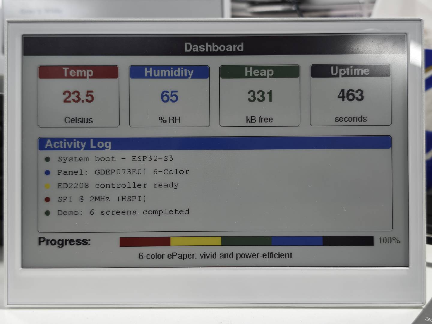
La siguiente figura muestra el efecto de visualización real del ejemplo E1002:
Programación de reTerminal E1003 (pantalla monocroma de 10,3")
El reTerminal E1003 incorpora una pantalla de tinta electrónica monocroma de 10,3" (1872×1404, panel ED103TC2, controlador IT8951). Es compatible con escala de grises de 16 niveles y requiere OPI PSRAM. Este ejemplo depende de un archivo de controlador personalizado GxEPD2_ED103TC2_1872x1404.h incluido en la carpeta del ejemplo.
Después de instalar la biblioteca Seeed_GxEPD2, puedes encontrar este ejemplo en el IDE de Arduino a través de File > Examples > Seeed_GxEPD2 > GxEPD2_reTerminal_E1003, o localizarlo manualmente en Seeed_GxEPD2/examples/GxEPD2_reTerminal_E1003/.
El E1003 requiere que OPI PSRAM esté habilitado en el IDE de Arduino: Tools > PSRAM > OPI PSRAM. El framebuffer de ~321 kB reside en la PSRAM.
Haz clic aquí para ver el código completo
#include <SPI.h>
#include <GxEPD2_BW.h>
#include <Fonts/FreeMonoBold9pt7b.h>
#include <Fonts/FreeMonoBold12pt7b.h>
#include <Fonts/FreeSansBold24pt7b.h>
#include <Fonts/FreeSansBold18pt7b.h>
#include <Fonts/FreeSansBold12pt7b.h>
#include <Fonts/FreeSans9pt7b.h>
#include <Fonts/FreeMono9pt7b.h>

#include "GxEPD2_ED103TC2_1872x1404.h"

#define DBG Serial0

// ===== reTerminal E1003 pin mapping =====
#define EPD_SCK_PIN       7
#define EPD_MISO_PIN      8
#define EPD_MOSI_PIN      9
#define EPD_CS_PIN        10
#define EPD_RES_PIN       12
#define EPD_BUSY_PIN      13
#define EPD_TFT_ENABLE    11
#define EPD_ITE_ENABLE    21

SPIClass hspi(HSPI);

// ===== Display object =====
#define MAX_DISPLAY_BUFFER_SIZE 65536u
#define MAX_HEIGHT(EPD) \
    (EPD::HEIGHT <= MAX_DISPLAY_BUFFER_SIZE / (EPD::WIDTH / 8) \
         ? EPD::HEIGHT \
         : MAX_DISPLAY_BUFFER_SIZE / (EPD::WIDTH / 8))

GxEPD2_BW<GxEPD2_ED103TC2_1872x1404, MAX_HEIGHT(GxEPD2_ED103TC2_1872x1404)>
    display(GxEPD2_ED103TC2_1872x1404(EPD_CS_PIN, -1, EPD_RES_PIN, EPD_BUSY_PIN));

// ===== Layout constants =====
static const int HEADER_H = 96;
static const int FOOTER_H = 72;
static const int PAGE_MARGIN = 48;
static const int PANEL_GAP = 24;

// ===== Forward declarations =====
void showSplashScreen();
void showSystemInfo();
void showGeometryDemo();
void showPatternDemo();
void showTypographyDemo();
void showDashboardDemo();

void drawCenteredText(const char* text, int16_t y, const GFXfont* font);
void drawCenteredTextInBox(const char* text, int16_t x, int16_t y, int16_t w, int16_t h, const GFXfont* font);
void drawPageHeader(const char* title, const char* subtitle);
void drawPageFooter(const char* text);
void drawPanelFrame(int x, int y, int w, int h);
void drawCardShell(int x, int y, int w, int h, const char* title);
void drawMetricCard(int x, int y, int w, int h, const char* title, const char* value, const char* unit);
void drawInfoCard(int x, int y, int w, int h, const char* label, const char* value, const GFXfont* valueFont);
void drawTypographyCard(int x, int y, int w, int h, const char* title, const char* sample, const GFXfont* font);

// ===== Setup =====
void setup()
{
  DBG.begin(115200);
  delay(100);
  DBG.println();
  DBG.println(F("=================================================="));
  DBG.println(F("[E1003] GxEPD2 reTerminal E1003 Demo"));
  DBG.print  (F("[E1003] PSRAM = ")); DBG.print(ESP.getPsramSize() / 1024);
  DBG.println(F(" kB"));
  DBG.println(F("=================================================="));

  pinMode(EPD_TFT_ENABLE, OUTPUT); digitalWrite(EPD_TFT_ENABLE, HIGH);
  pinMode(EPD_ITE_ENABLE, OUTPUT); digitalWrite(EPD_ITE_ENABLE, HIGH);
  delay(50);

  pinMode(EPD_RES_PIN, OUTPUT);
  pinMode(EPD_CS_PIN,  OUTPUT); digitalWrite(EPD_CS_PIN, HIGH);

  hspi.begin(EPD_SCK_PIN, EPD_MISO_PIN, EPD_MOSI_PIN, -1);
  display.epd2.selectSPI(hspi, SPISettings(10000000, MSBFIRST, SPI_MODE0));

  display.init(0, true, 10, false);
  DBG.println(F("[E1003] display initialized"));

  // --- Run demo screens ---
  DBG.println(F("[E1003] Screen 1: Splash"));
  showSplashScreen();
  delay(5000);

  DBG.println(F("[E1003] Screen 2: System Info"));
  showSystemInfo();
  delay(5000);

  DBG.println(F("[E1003] Screen 3: Typography"));
  showTypographyDemo();
  delay(5000);

  DBG.println(F("[E1003] Screen 4: Geometry"));
  showGeometryDemo();
  delay(5000);

  DBG.println(F("[E1003] Screen 5: Patterns"));
  showPatternDemo();
  delay(5000);

  DBG.println(F("[E1003] Screen 6: Dashboard"));
  showDashboardDemo();

  DBG.println(F("[E1003] Demo complete. Hibernating."));
  delay(2000);
  display.hibernate();
}

void loop() {}

// =====================================================================
// Helpers
// =====================================================================
void drawCenteredText(const char* text, int16_t y, const GFXfont* font)
{
  display.setFont(font);
  int16_t tbx, tby;
  uint16_t tbw, tbh;
  display.getTextBounds(text, 0, 0, &tbx, &tby, &tbw, &tbh);
  display.setCursor((display.width() - tbw) / 2 - tbx, y);
  display.print(text);
}

void drawCenteredTextInBox(const char* text, int16_t x, int16_t y, int16_t w, int16_t h, const GFXfont* font)
{
  if (!text) return;
  display.setFont(font);
  int16_t tbx, tby;
  uint16_t tbw, tbh;
  display.getTextBounds(text, 0, 0, &tbx, &tby, &tbw, &tbh);
  const int16_t cx = x + (w - tbw) / 2 - tbx;
  const int16_t cy = y + (h - tbh) / 2 - tby;
  display.setCursor(cx, cy);
  display.print(text);
}

void drawPageHeader(const char* title, const char* subtitle)
{
  const uint16_t W = display.width();
  display.fillRect(0, 0, W, HEADER_H, GxEPD_BLACK);

  display.setTextColor(GxEPD_WHITE);
  drawCenteredText(title, 40, &FreeSansBold18pt7b);

  if (subtitle && subtitle[0] != '\0') {
    drawCenteredText(subtitle, 78, &FreeSans9pt7b);
  }

  display.setTextColor(GxEPD_BLACK);
}

void drawPageFooter(const char* text)
{
  const uint16_t W = display.width();
  const uint16_t H = display.height();

  display.drawFastHLine(64, H - 60, W - 128, GxEPD_BLACK);
  display.setFont(&FreeSans9pt7b);
  drawCenteredText(text, H - 34, &FreeSans9pt7b);
}

void drawPanelFrame(int x, int y, int w, int h)
{
  display.drawRoundRect(x, y, w, h, 16, GxEPD_BLACK);
  display.drawRoundRect(x + 2, y + 2, w - 4, h - 4, 14, GxEPD_BLACK);
}

void drawCardShell(int x, int y, int w, int h, const char* title)
{
  drawPanelFrame(x, y, w, h);
  display.fillRoundRect(x + 4, y + 4, w - 8, 38, 10, GxEPD_BLACK);
  display.setTextColor(GxEPD_WHITE);
  drawCenteredTextInBox(title, x + 10, y + 8, w - 20, 24, &FreeSansBold12pt7b);
  display.setTextColor(GxEPD_BLACK);
}

void drawMetricCard(int x, int y, int w, int h, const char* title, const char* value, const char* unit)
{
  drawCardShell(x, y, w, h, title);
  drawCenteredTextInBox(value, x + 18, y + 58, w - 36, h - 108, &FreeSansBold24pt7b);

  if (unit && unit[0] != '\0') {
    display.setFont(&FreeSans9pt7b);
    drawCenteredTextInBox(unit, x + 20, y + h - 36, w - 40, 20, &FreeSans9pt7b);
  }
}

void drawInfoCard(int x, int y, int w, int h, const char* label, const char* value, const GFXfont* valueFont)
{
  drawCardShell(x, y, w, h, label);
  display.setTextColor(GxEPD_BLACK);
  drawCenteredTextInBox(value, x + 20, y + 54, w - 40, h - 78, valueFont);
}

void drawTypographyCard(int x, int y, int w, int h, const char* title, const char* sample, const GFXfont* font)
{
  drawCardShell(x, y, w, h, title);
  drawCenteredTextInBox(sample, x + 20, y + 54, w - 40, h - 78, font);
}

// =====================================================================
// Screen 1: Splash screen
// =====================================================================
void showSplashScreen()
{
  const uint16_t W = display.width();
  const uint16_t H = display.height();

  display.setRotation(0);
  display.setFullWindow();
  display.firstPage();
  do {
    display.fillScreen(GxEPD_WHITE);

    // Outer frame
    display.drawRect(24, 24, W - 48, H - 48, GxEPD_BLACK);
    display.drawRect(34, 34, W - 68, H - 68, GxEPD_BLACK);

    // Hero panel in the center
    const int heroX = 140;
    const int heroY = 150;
    const int heroW = W - 280;
    const int heroH = H - 420;

    drawPanelFrame(heroX, heroY, heroW, heroH);

    display.fillRoundRect(heroX + 6, heroY + 6, heroW - 12, 54, 12, GxEPD_BLACK);
    display.setTextColor(GxEPD_WHITE);
    drawCenteredTextInBox("reTerminal E1003", heroX + 20, heroY + 14, heroW - 40, 30, &FreeSansBold18pt7b);

    display.setTextColor(GxEPD_BLACK);
    drawCenteredTextInBox("10.3\" e-Paper Display", heroX + 40, heroY + 96, heroW - 80, 90, &FreeSansBold24pt7b);
    drawCenteredTextInBox("GxEPD2 + IT8951 Driver Demo", heroX + 40, heroY + 210, heroW - 80, 64, &FreeSansBold18pt7b);

    display.drawFastHLine(heroX + 120, heroY + 292, heroW - 240, GxEPD_BLACK);
    drawCenteredTextInBox("1872 x 1404 pixels | ED103TC2 panel", heroX + 40, heroY + 316, heroW - 80, 44, &FreeSansBold12pt7b);
    drawCenteredTextInBox("Powered by ESP32-S3 + PSRAM", heroX + 40, heroY + 366, heroW - 80, 34, &FreeSans9pt7b);

    // Bottom three badges
    const int badgeY = H - 180;
    const int badgeW = (W - 2 * PAGE_MARGIN - 2 * PANEL_GAP) / 3;
    const int badgeH = 92;
    const int badgeX1 = PAGE_MARGIN;
    const int badgeX2 = badgeX1 + badgeW + PANEL_GAP;
    const int badgeX3 = badgeX2 + badgeW + PANEL_GAP;

    drawPanelFrame(badgeX1, badgeY, badgeW, badgeH);
    drawPanelFrame(badgeX2, badgeY, badgeW, badgeH);
    drawPanelFrame(badgeX3, badgeY, badgeW, badgeH);

    drawCenteredTextInBox("Large Canvas", badgeX1 + 12, badgeY + 12, badgeW - 24, badgeH - 24, &FreeSansBold12pt7b);
    drawCenteredTextInBox("High Contrast", badgeX2 + 12, badgeY + 12, badgeW - 24, badgeH - 24, &FreeSansBold12pt7b);
    drawCenteredTextInBox("Low Power Image Hold", badgeX3 + 12, badgeY + 12, badgeW - 24, badgeH - 24, &FreeSansBold12pt7b);

    // Footer note
    drawCenteredText("Seeed Studio x GxEPD2", H - 70, &FreeSans9pt7b);

  } while (display.nextPage());
}

// =====================================================================
// Screen 2: System information
// =====================================================================
void showSystemInfo()
{
  const uint16_t W = display.width();
  const uint16_t H = display.height();

  display.setRotation(0);
  display.setFullWindow();
  display.firstPage();
  do {
    display.fillScreen(GxEPD_WHITE);
    drawPageHeader("System Information", "Hardware, memory and display details laid out as cards");

    const int contentX = PAGE_MARGIN;
    const int contentY = HEADER_H + 18;
    const int contentW = W - 2 * PAGE_MARGIN;
    const int contentH = H - HEADER_H - FOOTER_H - 36;
    const int gapX = PANEL_GAP;
    const int gapY = 16;
    const int cardW = (contentW - gapX) / 2;
    const int cardH = (contentH - 4 * gapY) / 5;

    char psramBuf[32], heapBuf[32], chipBuf[64], dispBuf[32], uptimeBuf[32];
    snprintf(psramBuf, sizeof(psramBuf), "%lu kB", (unsigned long)(ESP.getPsramSize() / 1024));
    snprintf(heapBuf,  sizeof(heapBuf),  "%lu kB free", (unsigned long)(ESP.getFreeHeap() / 1024));
    snprintf(chipBuf,  sizeof(chipBuf),  "ESP32-S3 @ %lu MHz", (unsigned long)(ESP.getCpuFreqMHz()));
    snprintf(dispBuf,  sizeof(dispBuf),  "%d x %d", display.width(), display.height());
    unsigned long sec = millis() / 1000;
    snprintf(uptimeBuf, sizeof(uptimeBuf), "%lu.%01lu s", sec, (millis() % 1000) / 100);

    struct InfoCardSpec {
      const char* label;
      const char* value;
      const GFXfont* font;
    };

    InfoCardSpec cards[] = {
      {"MCU",        chipBuf,     &FreeSansBold18pt7b},
      {"PSRAM",      psramBuf,    &FreeSansBold18pt7b},
      {"Heap",       heapBuf,     &FreeSansBold18pt7b},
      {"Display",    dispBuf,     &FreeSansBold18pt7b},
      {"Panel",      "E Ink ED103TC2", &FreeSansBold12pt7b},
      {"Controller", "IT8951",    &FreeSansBold18pt7b},
      {"Interface",  "SPI (HSPI/SPI3) @ 10MHz", &FreeSansBold12pt7b},
      {"Color",      "Monochrome (BW)", &FreeSansBold18pt7b},
      {"Library",    "GxEPD2",    &FreeSansBold18pt7b},
      {"Uptime",     uptimeBuf,   &FreeSansBold18pt7b},
    };

    for (int i = 0; i < 10; i++) {
      const int col = i % 2;
      const int row = i / 2;
      const int x = contentX + col * (cardW + gapX);
      const int y = contentY + row * (cardH + gapY);
      drawInfoCard(x, y, cardW, cardH, cards[i].label, cards[i].value, cards[i].font);
    }

    drawPageFooter("reTerminal E1003 | GxEPD2 Demo");

  } while (display.nextPage());
}

// =====================================================================
// Screen 3: Typography showcase
// =====================================================================
void showTypographyDemo()
{
  const uint16_t W = display.width();
  const uint16_t H = display.height();

  display.setRotation(0);
  display.setFullWindow();
  display.firstPage();
  do {
    display.fillScreen(GxEPD_WHITE);
    drawPageHeader("Typography Demo", "Font families and sizes shown in a balanced card grid");

    const int contentX = PAGE_MARGIN;
    const int contentY = HEADER_H + 18;
    const int contentW = W - 2 * PAGE_MARGIN;
    const int contentH = H - HEADER_H - FOOTER_H - 36;
    const int gapX = PANEL_GAP;
    const int gapY = PANEL_GAP;
    const int cardW = (contentW - gapX) / 2;
    const int cardH = (contentH - 2 * gapY) / 3;

    drawTypographyCard(contentX,                    contentY,                    cardW, cardH, "FreeSans Bold 24pt", "Display Title", &FreeSansBold24pt7b);
    drawTypographyCard(contentX + cardW + gapX,     contentY,                    cardW, cardH, "FreeSans Bold 18pt", "Section Heading", &FreeSansBold18pt7b);
    drawTypographyCard(contentX,                    contentY + cardH + gapY,     cardW, cardH, "FreeSans Bold 12pt", "Clean and readable", &FreeSansBold12pt7b);
    drawTypographyCard(contentX + cardW + gapX,     contentY + cardH + gapY,     cardW, cardH, "FreeSans 9pt", "Body text for dense data", &FreeSans9pt7b);
    drawTypographyCard(contentX,                    contentY + 2 * (cardH + gapY), cardW, cardH, "FreeMono Bold 12pt", "0123456789 ABCDEF", &FreeMonoBold12pt7b);
    drawTypographyCard(contentX + cardW + gapX,     contentY + 2 * (cardH + gapY), cardW, cardH, "FreeMono 9pt", "Code / tables / logs", &FreeMono9pt7b);

    drawPageFooter("Typography is easier to scan when the page is divided into readable blocks");

  } while (display.nextPage());
}

// =====================================================================
// Screen 4: Geometric shapes
// =====================================================================
void showGeometryDemo()
{
  const uint16_t W = display.width();
  const uint16_t H = display.height();

  display.setRotation(0);
  display.setFullWindow();
  display.firstPage();
  do {
    display.fillScreen(GxEPD_WHITE);
    drawPageHeader("Geometry & Shapes Demo", "Each panel gets enough space to breathe");

    const int contentX = PAGE_MARGIN;
    const int contentY = HEADER_H + 18;
    const int contentW = W - 2 * PAGE_MARGIN;
    const int contentH = H - HEADER_H - FOOTER_H - 36;
    const int gapX = PANEL_GAP;
    const int gapY = PANEL_GAP;
    const int panelW = (contentW - gapX) / 2;
    const int panelH = (contentH - gapY) / 2;

    // Top-left: rectangles
    const int p1x = contentX;
    const int p1y = contentY;
    drawCardShell(p1x, p1y, panelW, panelH, "Rectangles");
    for (int i = 0; i < 4; i++) {
      display.drawRect(p1x + 80 + i * 130, p1y + 100 + i * 10, 100, 70, GxEPD_BLACK);
    }
    display.fillRect(p1x + 650, p1y + 100, 120, 90, GxEPD_BLACK);
    display.drawRect(p1x + 620, p1y + 70, 160, 150, GxEPD_BLACK);

    // Top-right: circles
    const int p2x = contentX + panelW + gapX;
    const int p2y = contentY;
    drawCardShell(p2x, p2y, panelW, panelH, "Circles");
    for (int i = 0; i < 5; i++) {
      display.drawCircle(p2x + 130 + i * 120, p2y + 150, 28 + i * 7, GxEPD_BLACK);
    }
    for (int i = 0; i < 4; i++) {
      display.fillCircle(p2x + 170 + i * 150, p2y + 340, 18 + i * 6, GxEPD_BLACK);
    }

    // Bottom-left: triangles and line fan
    const int p3x = contentX;
    const int p3y = contentY + panelH + gapY;
    drawCardShell(p3x, p3y, panelW, panelH, "Triangles and Lines");
    for (int i = 0; i < 5; i++) {
      int tx = p3x + 90 + i * 120;
      int ty = p3y + 120;
      int sz = 70 + i * 10;
      display.drawTriangle(tx, ty + sz, tx + sz / 2, ty, tx + sz, ty + sz, GxEPD_BLACK);
    }
    const int fanCx = p3x + 180;
    const int fanCy = p3y + 380;
    for (int angle = 0; angle < 180; angle += 12) {
      const float rad = angle * 3.1415926f / 180.0f;
      const int ex = fanCx + (int)(150.0f * cosf(rad));
      const int ey = fanCy - (int)(150.0f * sinf(rad));
      display.drawLine(fanCx, fanCy, ex, ey, GxEPD_BLACK);
    }

    // Bottom-right: concentric circles and rounded rectangles
    const int p4x = contentX + panelW + gapX;
    const int p4y = contentY + panelH + gapY;
    drawCardShell(p4x, p4y, panelW, panelH, "Rounded Shapes");
    const int ccx = p4x + 240;
    const int ccy = p4y + 235;
    for (int r = 30; r <= 150; r += 24) {
      display.drawCircle(ccx, ccy, r, GxEPD_BLACK);
    }
    const int rrx = p4x + 520;
    const int rry = p4y + 120;
    for (int i = 0; i < 4; i++) {
      display.drawRoundRect(rrx + i * 14, rry + i * 14,
                            250 - i * 28, 230 - i * 28,
                            24 - i * 3, GxEPD_BLACK);
    }

    drawPageFooter("Adafruit GFX primitives on a wide e-paper canvas");

  } while (display.nextPage());
}

// =====================================================================
// Screen 5: Patterns
// =====================================================================
void showPatternDemo()
{
  const uint16_t W = display.width();
  const uint16_t H = display.height();

  display.setRotation(0);
  display.setFullWindow();
  display.firstPage();
  do {
    display.fillScreen(GxEPD_WHITE);
    drawPageHeader("Pattern & Fill Demo", "Six pattern tiles arranged in a clean 3 x 2 grid");

    const int contentX = PAGE_MARGIN;
    const int contentY = HEADER_H + 18;
    const int contentW = W - 2 * PAGE_MARGIN;
    const int contentH = H - HEADER_H - FOOTER_H - 36;
    const int gapX = PANEL_GAP;
    const int gapY = PANEL_GAP;
    const int tileW = (contentW - 2 * gapX) / 3;
    const int tileH = (contentH - gapY) / 2;

    struct TileSpec {
      const char* title;
    };

    TileSpec tiles[] = {
      {"Checkerboard"},
      {"H-Stripes"},
      {"V-Stripes"},
      {"Dot Grid"},
      {"Diagonal"},
      {"Dither Gradient"},
    };

    for (int i = 0; i < 6; i++) {
      const int col = i % 3;
      const int row = i / 3;
      const int x = contentX + col * (tileW + gapX);
      const int y = contentY + row * (tileH + gapY);
      drawCardShell(x, y, tileW, tileH, tiles[i].title);

      const int innerX = x + 16;
      const int innerY = y + 58;
      const int innerW = tileW - 32;
      const int innerH = tileH - 74;

      if (i == 0) {
        const int sz = 22;
        for (int py = 0; py < innerH / sz + 1; py++) {
          for (int px = 0; px < innerW / sz + 1; px++) {
            if ((px + py) & 1) {
              display.fillRect(innerX + px * sz, innerY + py * sz, sz, sz, GxEPD_BLACK);
            }
          }
        }
      } else if (i == 1) {
        for (int py = 0; py < innerH; py += 14) {
          if ((py / 14) & 1) {
            display.fillRect(innerX, innerY + py, innerW, 14, GxEPD_BLACK);
          }
        }
      } else if (i == 2) {
        for (int px = 0; px < innerW; px += 14) {
          if ((px / 14) & 1) {
            display.fillRect(innerX + px, innerY, 14, innerH, GxEPD_BLACK);
          }
        }
      } else if (i == 3) {
        for (int py = 0; py < innerH; py += 22) {
          for (int px = 0; px < innerW; px += 22) {
            display.fillCircle(innerX + px + 11, innerY + py + 11, 4, GxEPD_BLACK);
          }
        }
      } else if (i == 4) {
        display.drawRect(innerX, innerY, innerW, innerH, GxEPD_BLACK);
        for (int d = -innerH; d < innerW; d += 18) {
          int x0 = innerX + max(0, d);
          int y0 = innerY + max(0, -d);
          int x1 = innerX + min(innerW - 1, d + innerH - 1);
          int y1 = innerY + min(innerH - 1, -d + innerW - 1);
          display.drawLine(x0, y0, x1, y1, GxEPD_BLACK);
        }
      } else {
        display.drawRect(innerX, innerY, innerW, innerH, GxEPD_BLACK);
        for (int py = 0; py < innerH; py++) {
          for (int px = 0; px < innerW; px++) {
            int density = (px * 255) / innerW;
            if ((((px * 7 + py * 13) ^ (px * py)) & 0xFF) < density) {
              display.drawPixel(innerX + px, innerY + py, GxEPD_BLACK);
            }
          }
        }
      }
    }

    drawPageFooter("Patterns are easier to compare when each sample gets the same amount of space");

  } while (display.nextPage());
}

// =====================================================================
// Screen 6: Dashboard-style layout
// =====================================================================
void showDashboardDemo()
{
  const uint16_t W = display.width();
  const uint16_t H = display.height();

  display.setRotation(0);
  display.setFullWindow();
  display.firstPage();
  do {
    display.fillScreen(GxEPD_WHITE);
    drawPageHeader("Dashboard Demo", "A large, readable layout with metrics, logs and a status bar");

    const int contentX = PAGE_MARGIN;
    const int contentY = HEADER_H + 18;
    const int contentW = W - 2 * PAGE_MARGIN;
    const int contentH = H - HEADER_H - FOOTER_H - 36;
    const int gapX = PANEL_GAP;
    const int gapY = PANEL_GAP;

    // Top row metrics
    const int metricH = 220;
    const int metricW = (contentW - 3 * gapX) / 4;

    char uptimeBuf[16];
    snprintf(uptimeBuf, sizeof(uptimeBuf), "%lu", millis() / 1000);

    char heapBuf[16];
    snprintf(heapBuf, sizeof(heapBuf), "%lu", (unsigned long)(ESP.getFreeHeap() / 1024));

    drawMetricCard(contentX + 0 * (metricW + gapX), contentY, metricW, metricH, "Temperature", "23.5", "Celsius");
    drawMetricCard(contentX + 1 * (metricW + gapX), contentY, metricW, metricH, "Humidity", "65", "% RH");
    drawMetricCard(contentX + 2 * (metricW + gapX), contentY, metricW, metricH, "Free Heap", heapBuf, "kB");
    drawMetricCard(contentX + 3 * (metricW + gapX), contentY, metricW, metricH, "Uptime", uptimeBuf, "seconds");

    // Activity log panel
    const int logY = contentY + metricH + gapY;
    const int logH = 460;
    drawCardShell(contentX, logY, contentW, logH, "Activity Log");

    const char* logEntries[] = {
      "[00:00:01] System boot complete - ESP32-S3 @ 240MHz",
      "[00:00:02] PSRAM initialized: 8192 kB available",
      "[00:00:03] IT8951 controller detected (FW: eSee_d.v.0)",
      "[00:00:03] Panel: ED103TC2 1872x1404, VCOM=-1.40V",
      "[00:00:04] SPI bus configured: HSPI @ 10MHz",
      "[00:00:05] Display driver ready - full refresh mode",
      "[00:00:06] Demo sequence started...",
    };

    display.setFont(&FreeMono9pt7b);
    const int lineX = contentX + 24;
    const int lineY = logY + 72;
    const int lineH = 48;

    for (int i = 0; i < 7; i++) {
      display.setCursor(lineX, lineY + i * lineH);
      display.print(logEntries[i]);
      if (i < 6) {
        display.drawFastHLine(contentX + 20, lineY + i * lineH + 18, contentW - 40, GxEPD_BLACK);
      }
    }

    // Bottom status strip
    const int statusY = logY + logH + gapY;
    const int statusH = contentH - metricH - logH - 2 * gapY;
    drawPanelFrame(contentX, statusY, contentW, statusH);

    display.fillRoundRect(contentX + 4, statusY + 4, contentW - 8, 42, 10, GxEPD_BLACK);
    display.setTextColor(GxEPD_WHITE);
    drawCenteredTextInBox("Progress", contentX + 20, statusY + 10, 160, 24, &FreeSansBold12pt7b);

    const int barX = contentX + 180;
    const int barY = statusY + 18;
    const int barW = contentW - 360;
    const int barH = 28;

    display.setTextColor(GxEPD_BLACK);
    display.drawRect(barX, barY, barW, barH, GxEPD_BLACK);
    display.fillRect(barX + 2, barY + 2, barW - 4, barH - 4, GxEPD_BLACK);

    display.setFont(&FreeSans9pt7b);
    display.setCursor(barX + barW + 16, barY + 22);
    display.print("100% - Demo Complete!");

    display.setFont(&FreeSans9pt7b);
    display.setCursor(contentX + 24, statusY + statusH - 18);
    display.print("E-paper is ideal for dashboards: the image stays visible without refresh power");

    drawPageFooter("Wide screens work better when the key information is grouped into strong blocks");

  } while (display.nextPage());
}
La siguiente figura muestra el efecto de visualización real del ejemplo E1003:
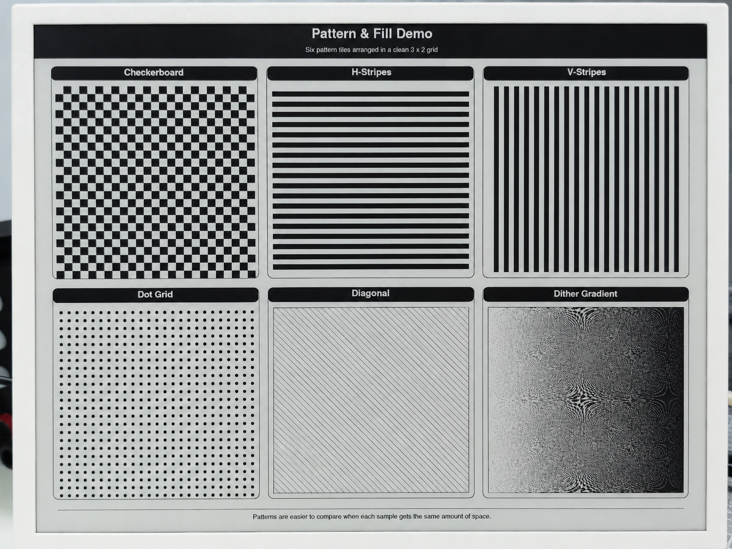
El código fuente completo para el ejemplo E1003 (incluyendo las 6 pantallas de demostración con implementaciones completas para Splash, System Info, Typography, Geometry, Patterns y Dashboard) está disponible en el repositorio en Seeed_GxEPD2/examples/GxEPD2_reTerminal_E1003/. El ejemplo incluye funciones auxiliares para texto centrado, encabezados/pies de página y diseños tipo tarjeta optimizados para la gran pantalla de 10.3".
Programación de reTerminal E1004 (pantalla de 13.3" y 6 colores)
El reTerminal E1004 incorpora una pantalla de tinta electrónica de 13.3" y 6 colores (1200×1600, panel T133A01, controlador de doble chip, Spectra 6). Es compatible con negro, blanco, rojo, verde, azul y amarillo. Este ejemplo depende de un archivo de controlador personalizado GxEPD2_T133A01_1200x1600.h incluido en la carpeta del ejemplo.
Después de instalar la biblioteca Seeed_GxEPD2, puedes encontrar este ejemplo en el IDE de Arduino a través de File > Examples > Seeed_GxEPD2 > GxEPD2_reTerminal_E1004, o localizarlo manualmente en Seeed_GxEPD2/examples/GxEPD2_reTerminal_E1004/.
El E1004 requiere que OPI PSRAM esté habilitado en el IDE de Arduino: Tools > PSRAM > OPI PSRAM. El framebuffer de ~937 KB reside en la PSRAM.
Haz clic aquí para ver el código completo
#include <SPI.h>
#include <GxEPD2_7C.h>
#include "GxEPD2_T133A01_1200x1600.h"

// reTerminal serial monitor uses UART0.  With "USB CDC On Boot: Enabled",
// Serial = USB CDC, Serial0 = UART0 (the physical TX/RX pads on the board).
// All driver-level diagnostic output is sent through Serial0.
#define DBG Serial0
#include <Fonts/FreeMonoBold9pt7b.h>
#include <Fonts/FreeMonoBold12pt7b.h>
#include <Fonts/FreeSansBold24pt7b.h>
#include <Fonts/FreeSansBold18pt7b.h>
#include <Fonts/FreeSansBold12pt7b.h>
#include <Fonts/FreeSans9pt7b.h>
#include <Fonts/FreeMono9pt7b.h>

// ===== Pin mapping =====
#define EPD_SCK_PIN   7
#define EPD_MISO_PIN  8
#define EPD_MOSI_PIN  9
#define EPD_CS_PIN    10
#define EPD_DC_PIN    11
#define EPD_CS1_PIN   2
#define EPD_RES_PIN   38
#define EPD_BUSY_PIN  13
#define EPD_ENABLE_PIN 12

SPIClass hspi(HSPI);

// ===== Display: 13.3" 6-Color 1200x1600, dual-chip =====
#define MAX_DISPLAY_BUFFER_SIZE 24000u
#define MAX_HEIGHT(EPD) \
    (EPD::HEIGHT <= (MAX_DISPLAY_BUFFER_SIZE) / (EPD::WIDTH / 2) \
         ? EPD::HEIGHT \
         : (MAX_DISPLAY_BUFFER_SIZE) / (EPD::WIDTH / 2))

GxEPD2_7C<GxEPD2_T133A01_1200x1600, MAX_HEIGHT(GxEPD2_T133A01_1200x1600)>
    display(GxEPD2_T133A01_1200x1600(EPD_CS_PIN, EPD_DC_PIN, EPD_RES_PIN,
                                      EPD_BUSY_PIN, EPD_CS1_PIN, EPD_ENABLE_PIN));

// Color shorthand — T133A01 is a Spectra 6 panel.  Only these six
// colors are physically reproducible; the demo never references
// GxEPD_ORANGE because the panel has no native orange ink.
#define C_BLACK   GxEPD_BLACK
#define C_WHITE   GxEPD_WHITE
#define C_GREEN   GxEPD_GREEN
#define C_BLUE    GxEPD_BLUE
#define C_RED     GxEPD_RED
#define C_YELLOW  GxEPD_YELLOW

void setup()
{
  Serial.begin(115200);
  DBG.begin(115200);     // hardware UART0 (where the user's serial monitor is attached)
  delay(200);
  Serial.println(F("[E1004] GxEPD2 reTerminal E1004 Demo (13.3\" 6-Color)"));
  DBG.println(F("[E1004] GxEPD2 reTerminal E1004 Demo (13.3\" 6-Color)"));

  hspi.begin(EPD_SCK_PIN, EPD_MISO_PIN, EPD_MOSI_PIN, -1);
  // Match Seeed_GFX: 10 MHz SPI clock (XIAO_SPI_Frequency.h)
  display.epd2.selectSPI(hspi, SPISettings(10000000, MSBFIRST, SPI_MODE0));
  display.init(115200);  // enable diagnostic prints over Serial0/UART0

  // E1004 is a 13.3" 6-color panel — full refresh itself takes around 40s.
  // Keep each rendered page visible for at least 60s before moving on.
  const uint32_t PAGE_HOLD_MS = 60000;

  Serial.println(F("[E1004] Screen 1: Splash"));
  showSplashScreen();
  delay(PAGE_HOLD_MS);

  Serial.println(F("[E1004] Screen 2: Color Palette"));
  showColorPalette();
  delay(PAGE_HOLD_MS);

  Serial.println(F("[E1004] Screen 3: Typography"));
  showColorTypography();
  delay(PAGE_HOLD_MS);

  Serial.println(F("[E1004] Screen 4: Geometry"));
  showColorGeometry();
  delay(PAGE_HOLD_MS);

  Serial.println(F("[E1004] Screen 5: Patterns"));
  showColorPatterns();
  delay(PAGE_HOLD_MS);

  Serial.println(F("[E1004] Screen 6: Dashboard"));
  showDashboard();
  delay(PAGE_HOLD_MS);

  Serial.println(F("[E1004] Demo complete. Hibernating."));
  display.hibernate();
}

void loop() {}

// =====================================================================
void drawCenteredText(const char* text, int16_t y, const GFXfont* font)
{
  display.setFont(font);
  int16_t tbx, tby; uint16_t tbw, tbh;
  display.getTextBounds(text, 0, 0, &tbx, &tby, &tbw, &tbh);
  display.setCursor((display.width() - tbw) / 2 - tbx, y);
  display.print(text);
}

// =====================================================================
// Screen 1: Splash
// =====================================================================
void showSplashScreen()
{
  const uint16_t W = display.width();
  const uint16_t H = display.height();
  display.setRotation(0);
  display.setFullWindow();
  display.firstPage();
  do {
    display.fillScreen(C_WHITE);

    // Colorful top band (5 panel colors, excluding white)
    uint16_t colors[] = {C_RED, C_YELLOW, C_GREEN, C_BLUE, C_BLACK};
    int stripeW = (W - 40) / 5;
    for (int i = 0; i < 5; i++)
      display.fillRect(20 + i * stripeW, 20, stripeW, 16, colors[i]);

    display.drawRect(20, 50, W - 40, H - 70, C_BLACK);
    display.drawRect(24, 54, W - 48, H - 78, C_BLACK);

    display.setTextColor(C_BLACK);
    drawCenteredText("reTerminal E1004", H / 2 - 120, &FreeSansBold24pt7b);

    display.setTextColor(C_RED);
    drawCenteredText("13.3\" 6-Color e-Paper", H / 2 - 60, &FreeSansBold18pt7b);

    display.drawFastHLine(W / 4, H / 2 - 20, W / 2, C_BLUE);

    display.setTextColor(C_GREEN);
    drawCenteredText("GxEPD2 + T133A01 Driver", H / 2 + 20, &FreeSansBold18pt7b);

    display.setTextColor(C_BLUE);
    drawCenteredText("1200 x 1600 | Dual-Chip | 6 Colors", H / 2 + 70, &FreeSansBold12pt7b);

    display.setTextColor(C_RED);
    drawCenteredText("PSRAM framebuffer | ~937 KB", H / 2 + 110, &FreeSans9pt7b);

    // Bottom colorful band (reverse order)
    for (int i = 0; i < 5; i++)
      display.fillRect(20 + i * stripeW, H - 36, stripeW, 16, colors[4 - i]);

    display.setTextColor(C_BLACK);
    drawCenteredText("Seeed Studio x GxEPD2", H - 50, &FreeSans9pt7b);
  } while (display.nextPage());
}

// =====================================================================
// Screen 2: Color Palette
// =====================================================================
void showColorPalette()
{
  const uint16_t W = display.width();
  const uint16_t H = display.height();
  display.setRotation(0);
  display.setFullWindow();
  display.firstPage();
  do {
    display.fillScreen(C_WHITE);
    display.fillRect(0, 0, W, 50, C_BLACK);
    display.setTextColor(C_WHITE);
    drawCenteredText("6-Color Palette", 38, &FreeSansBold18pt7b);

    const uint16_t swatchColors[] = {C_BLACK, C_WHITE, C_RED, C_GREEN, C_BLUE, C_YELLOW};
    const char* names[] = {"Black", "White", "Red", "Green", "Blue", "Yellow"};
    int sw = 160, sh = 180, gap = 14;
    int sx = (W - 6 * sw - 5 * gap) / 2;
    int sy = 90;

    for (int i = 0; i < 6; i++) {
      int x = sx + i * (sw + gap);
      display.fillRoundRect(x, sy, sw, sh, 8, swatchColors[i]);
      display.drawRoundRect(x, sy, sw, sh, 8, C_BLACK);
      display.setFont(&FreeSansBold12pt7b);
      display.setTextColor(C_BLACK);
      int16_t tbx, tby; uint16_t tbw, tbh;
      display.getTextBounds(names[i], 0, 0, &tbx, &tby, &tbw, &tbh);
      display.setCursor(x + (sw - tbw) / 2 - tbx, sy + sh + 30);
      display.print(names[i]);
    }

    // Color combos (circles on colored backgrounds)
    int row2Y = sy + sh + 85;
    display.setFont(&FreeSansBold12pt7b);
    display.setTextColor(C_BLACK);
    display.setCursor(sx, row2Y - 10);
    display.print("Color combinations:");

    int cx = sx + 20;
    uint16_t bgCols[] = {C_RED, C_GREEN, C_BLUE, C_YELLOW, C_BLACK};
    uint16_t fgCols[] = {C_YELLOW, C_RED, C_GREEN, C_BLUE, C_RED};
    for (int i = 0; i < 5; i++) {
      int x = cx + i * 180;
      display.fillRoundRect(x, row2Y + 10, 150, 120, 10, bgCols[i]);
      display.fillCircle(x + 75, row2Y + 70, 40, fgCols[i]);
    }

    // Full-width bars
    int barY = row2Y + 180;
    display.setTextColor(C_BLACK);
    display.setCursor(sx, barY - 10);
    display.print("Full-width color bars:");
    uint16_t barCols[] = {C_RED, C_YELLOW, C_GREEN, C_BLUE, C_BLACK};
    for (int i = 0; i < 5; i++)
      display.fillRect(sx, barY + 10 + i * 32, W - 2 * sx, 24, barCols[i]);

    // Large circle ring composition
    int ringY = barY + 240;
    display.setTextColor(C_BLACK);
    display.setCursor(sx, ringY - 10);
    display.print("Overlapping circles:");
    uint16_t ringColors[] = {C_RED, C_YELLOW, C_GREEN, C_BLUE, C_BLACK};
    for (int i = 0; i < 5; i++)
      display.fillCircle(sx + 100 + i * 200, ringY + 100, 80, ringColors[i]);

    drawCenteredText("All 6 colors on 13.3\" e-Paper", H - 30, &FreeSans9pt7b);
  } while (display.nextPage());
}

// =====================================================================
// Screen 3: Typography
// =====================================================================
void showColorTypography()
{
  const uint16_t W = display.width();
  const uint16_t H = display.height();
  display.setRotation(0);
  display.setFullWindow();
  display.firstPage();
  do {
    display.fillScreen(C_WHITE);
    display.fillRect(0, 0, W, 50, C_BLUE);
    display.setTextColor(C_WHITE);
    drawCenteredText("Color Typography", 38, &FreeSansBold18pt7b);

    int y = 110, x = 50;

    // Large colored headings
    display.setTextColor(C_BLACK);
    display.setFont(&FreeSansBold24pt7b);
    display.setCursor(x, y); display.print("Black 24pt");
    display.setTextColor(C_RED);
    display.setCursor(x + 420, y); display.print("Red 24pt");
    y += 75;

    display.setTextColor(C_GREEN);
    display.setFont(&FreeSansBold24pt7b);
    display.setCursor(x, y); display.print("Green");
    display.setTextColor(C_BLUE);
    display.setCursor(x + 280, y); display.print("Blue");
    display.setTextColor(C_YELLOW);
    display.setCursor(x + 500, y); display.print("Yellow");
    y += 85;

    display.setTextColor(C_YELLOW);
    display.setFont(&FreeSansBold18pt7b);
    display.setCursor(x, y); display.print("Yellow 18pt - warm sunshine");
    y += 72;

    display.drawFastHLine(x, y, W - 100, C_RED);
    y += 35;

    // Color text on color backgrounds
    display.setFont(&FreeSansBold12pt7b);
    uint16_t bgColors[] = {C_RED, C_GREEN, C_BLUE, C_YELLOW, C_BLACK, C_WHITE};
    const char* labels[] = {
      " White on Red ", " White on Green ", " White on Blue ",
      " Black on Yellow ", " Red on Black ", " Black on White "
    };
    uint16_t fgText[] = {C_WHITE, C_WHITE, C_WHITE, C_BLACK, C_RED, C_BLACK};
    for (int i = 0; i < 6; i++) {
      int bx = (i < 3) ? x : x + 500;
      int by = y + (i % 3) * 65;
      display.fillRoundRect(bx, by, 400, 45, 6, bgColors[i]);
      display.setTextColor(fgText[i]);
      display.setCursor(bx + 15, by + 32);
      display.print(labels[i]);
    }
    y += 240;

    // Right-side: black box with colored text
    int rbx = x, rby = y;
    display.fillRoundRect(rbx, rby, W - 100, 420, 10, C_BLACK);
    display.setFont(&FreeSansBold24pt7b);
    int ry = rby + 60;
    uint16_t rColors[] = {C_RED, C_GREEN, C_BLUE, C_YELLOW, C_WHITE};
    const char* rLabels[] = {"Red on Dark", "Green on Dark", "Blue on Dark",
                              "Yellow on Dark", "White on Dark"};
    for (int i = 0; i < 5; i++) {
      display.setTextColor(rColors[i]);
      display.setCursor(rbx + 30, ry);
      display.print(rLabels[i]);
      ry += 65;
    }

    display.setTextColor(C_BLACK);
    drawCenteredText("6-color text on 13.3\" panel", H - 30, &FreeSans9pt7b);
  } while (display.nextPage());
}

// =====================================================================
// Screen 4: Geometry
// =====================================================================
void showColorGeometry()
{
  const uint16_t W = display.width();
  const uint16_t H = display.height();
  display.setRotation(0);
  display.setFullWindow();
  display.firstPage();
  do {
    display.fillScreen(C_WHITE);
    display.fillRect(0, 0, W, 50, C_GREEN);
    display.setTextColor(C_WHITE);
    drawCenteredText("Color Geometry", 38, &FreeSansBold18pt7b);
    display.setTextColor(C_BLACK);

    // Cascading colored rectangles
    uint16_t rColors[] = {C_RED, C_YELLOW, C_GREEN, C_BLUE, C_BLACK};
    for (int i = 0; i < 5; i++)
      display.fillRect(50 + i * 55, 80 + i * 15, 150, 90, rColors[i]);

    // Colored circles row
    uint16_t cColors[] = {C_BLUE, C_RED, C_GREEN, C_BLACK, C_YELLOW};
    for (int i = 0; i < 5; i++)
      display.fillCircle(600 + i * 100, 160, 40, cColors[i]);

    // Colored triangles
    int ty = 300;
    uint16_t triColors[] = {C_RED, C_GREEN, C_BLUE, C_YELLOW, C_BLACK};
    for (int i = 0; i < 5; i++) {
      int tx = 60 + i * 170;
      display.fillTriangle(tx, ty + 80, tx + 40, ty, tx + 80, ty + 80, triColors[i]);
    }

    // Olympic rings
    int ox = 250, oy = 500;
    uint16_t olyColors[] = {C_BLUE, C_BLACK, C_RED, C_YELLOW, C_GREEN};
    int olyX[] = {0, 90, 180, 45, 135};
    int olyY[] = {0, 0, 0, 50, 50};
    for (int i = 0; i < 5; i++)
      for (int r = 0; r < 5; r++)
        display.drawCircle(ox + olyX[i], oy + olyY[i], 40 - r, olyColors[i]);

    // Color mosaic (right side)
    int mx = 700, my = 450;
    display.setFont(&FreeSansBold12pt7b);
    display.setTextColor(C_BLACK);
    display.setCursor(mx, my - 10);
    display.print("Color Mosaic:");
    for (int py = 0; py < 6; py++)
      for (int px = 0; px < 6; px++) {
        uint16_t c = rColors[(px + py) % 5];
        display.fillRect(mx + px * 55, my + 10 + py * 55, 50, 50, c);
      }

    // Concentric colored circles (bottom)
    int cx = 300, cy = 850;
    uint16_t ccColors[] = {C_BLUE, C_GREEN, C_YELLOW, C_RED, C_BLACK};
    for (int i = 0; i < 5; i++)
      for (int r = 0; r < 5; r++)
        display.drawCircle(cx, cy, 70 - i * 12 + r, ccColors[i]);

    // Fan of colored lines
    int fx = 800, fy = 900;
    for (int a = 0; a < 180; a += 8) {
      float rad = a * 3.14159f / 180.0f;
      uint16_t lc = rColors[(a / 8) % 5];
      display.drawLine(fx, fy, fx + (int)(100 * cosf(rad)), fy - (int)(100 * sinf(rad)), lc);
    }

    // Large rounded rects (bottom section)
    int rrY = 1050;
    display.fillRoundRect(60, rrY, 250, 150, 15, C_RED);
    display.fillRoundRect(340, rrY, 250, 150, 15, C_GREEN);
    display.fillRoundRect(620, rrY, 250, 150, 15, C_BLUE);
    display.fillRoundRect(900, rrY, 250, 150, 15, C_YELLOW);

    display.setTextColor(C_WHITE);
    display.setFont(&FreeSansBold18pt7b);
    display.setCursor(90, rrY + 90); display.print("Red");
    display.setCursor(370, rrY + 90); display.print("Green");
    display.setCursor(660, rrY + 90); display.print("Blue");
    display.setTextColor(C_BLACK);
    display.setCursor(910, rrY + 90); display.print("Yellow");

    display.setTextColor(C_BLACK);
    drawCenteredText("GFX primitives on 13.3\" e-Paper", H - 30, &FreeSans9pt7b);
  } while (display.nextPage());
}

// =====================================================================
// Screen 5: Patterns
// =====================================================================
void showColorPatterns()
{
  const uint16_t W = display.width();
  const uint16_t H = display.height();
  display.setRotation(0);
  display.setFullWindow();
  display.firstPage();
  do {
    display.fillScreen(C_WHITE);
    display.fillRect(0, 0, W, 50, C_RED);
    display.setTextColor(C_WHITE);
    drawCenteredText("Color Patterns", 38, &FreeSansBold18pt7b);
    display.setTextColor(C_BLACK);
    display.setFont(&FreeSansBold12pt7b);

    uint16_t pColors[] = {C_RED, C_GREEN, C_BLUE, C_YELLOW, C_BLACK};
    int bx = 40, by = 75, bw = 230, bh = 230, gap = 30;

    // Color checkerboard
    display.setCursor(bx + 20, by + 20);
    display.print("Color Checker");
    int tby2 = by + 30;
    for (int py = 0; py < bh / 20; py++)
      for (int px = 0; px < bw / 20; px++)
        display.fillRect(bx + px * 20, tby2 + py * 20, 20, 20, pColors[(px + py) % 5]);

    // Horizontal stripes
    int bx2 = bx + bw + gap;
    display.setCursor(bx2 + 20, by + 20);
    display.print("H-Stripes");
    int tby3 = by + 30;
    for (int py = 0; py < bh; py += 20) {
      int ci = (py / 20) % 5;
      display.fillRect(bx2, tby3 + py, bw, 20, pColors[ci]);
    }

    // Vertical stripes
    int bx3 = bx2 + bw + gap;
    display.setCursor(bx3 + 20, by + 20);
    display.print("V-Stripes");
    int tby4 = by + 30;
    for (int px = 0; px < bw; px += 20) {
      int ci = (px / 20) % 5;
      display.fillRect(bx3 + px, tby4, 20, bh, pColors[ci]);
    }

    // Color dot grid
    int bx4 = bx3 + bw + gap;
    display.setCursor(bx4 + 20, by + 20);
    display.print("Color Dots");
    int tby5 = by + 30;
    for (int py = 0; py < bh; py += 24)
      for (int px = 0; px < bw; px += 24) {
        int ci = (px / 24 + py / 24) % 5;
        display.fillCircle(bx4 + px + 12, tby5 + py + 12, 8, pColors[ci]);
      }

    // Full-width rainbow bars
    int barY = tby5 + bh + 30;
    display.setFont(&FreeSansBold12pt7b);
    display.setCursor(bx, barY - 10);
    display.print("Rainbow bars:");
    for (int i = 0; i < 5; i++)
      display.fillRect(bx, barY + 10 + i * 30, W - 2 * bx, 24, pColors[i]);

    // Diamond pattern
    int diaY = barY + 210;
    display.setCursor(bx, diaY - 10);
    display.print("Diamond pattern:");
    for (int py = 0; py < 5; py++)
      for (int px = 0; px < 10; px++) {
        int cx2 = bx + 50 + px * 100;
        int cy2 = diaY + 20 + py * 60;
        uint16_t dc = pColors[(px + py) % 5];
        display.fillTriangle(cx2, cy2, cx2 - 30, cy2 + 30, cx2 + 30, cy2 + 30, dc);
        display.fillTriangle(cx2, cy2 + 60, cx2 - 30, cy2 + 30, cx2 + 30, cy2 + 30, dc);
      }

    drawCenteredText("Patterns with 6-color palette", H - 30, &FreeSans9pt7b);
  } while (display.nextPage());
}

// =====================================================================
// Screen 6: Dashboard
// =====================================================================
void drawColorCard(int x, int y, int w, int h, const char* title,
                   const char* value, const char* unit, uint16_t accent)
{
  display.drawRoundRect(x, y, w, h, 8, C_BLACK);
  display.fillRoundRect(x + 2, y + 2, w - 4, 34, 6, accent);
  display.setTextColor(C_WHITE);
  display.setFont(&FreeSansBold12pt7b);
  int16_t tbx, tby; uint16_t tbw, tbh;
  display.getTextBounds(title, 0, 0, &tbx, &tby, &tbw, &tbh);
  display.setCursor(x + (w - tbw) / 2 - tbx, y + 28);
  display.print(title);

  display.setTextColor(accent);
  display.setFont(&FreeSansBold24pt7b);
  display.getTextBounds(value, 0, 0, &tbx, &tby, &tbw, &tbh);
  display.setCursor(x + (w - tbw) / 2 - tbx, y + h / 2 + 15);
  display.print(value);

  display.setTextColor(C_BLACK);
  display.setFont(&FreeSans9pt7b);
  display.getTextBounds(unit, 0, 0, &tbx, &tby, &tbw, &tbh);
  display.setCursor(x + (w - tbw) / 2 - tbx, y + h - 15);
  display.print(unit);
}

void showDashboard()
{
  const uint16_t W = display.width();
  const uint16_t H = display.height();
  display.setRotation(0);
  display.setFullWindow();
  display.firstPage();
  do {
    display.fillScreen(C_WHITE);
    display.fillRect(0, 0, W, 50, C_BLACK);
    display.setTextColor(C_WHITE);
    drawCenteredText("Dashboard", 38, &FreeSansBold18pt7b);
    display.setTextColor(C_BLACK);

    int cw = 250, ch = 180, gap = 25;
    int sx = (W - 4 * cw - 3 * gap) / 2;
    int row1Y = 75;

    char uptBuf[16]; snprintf(uptBuf, sizeof(uptBuf), "%lu", millis() / 1000);
    char heapBuf[16]; snprintf(heapBuf, sizeof(heapBuf), "%lu", (unsigned long)(ESP.getFreeHeap() / 1024));

    drawColorCard(sx,                    row1Y, cw, ch, "Temp",     "23.5",  "Celsius",  C_RED);
    drawColorCard(sx + cw + gap,         row1Y, cw, ch, "Humidity", "65",    "% RH",     C_BLUE);
    drawColorCard(sx + 2 * (cw + gap),   row1Y, cw, ch, "Heap",    heapBuf, "kB free",  C_GREEN);
    drawColorCard(sx + 3 * (cw + gap),   row1Y, cw, ch, "Uptime",  uptBuf,  "seconds",  C_YELLOW);

    // Activity log
    int logY = row1Y + ch + 30;
    display.drawRoundRect(sx, logY, W - 2 * sx, 300, 8, C_BLACK);
    display.fillRoundRect(sx + 2, logY + 2, W - 2 * sx - 4, 34, 6, C_BLUE);
    display.setTextColor(C_WHITE);
    display.setFont(&FreeSansBold12pt7b);
    display.setCursor(sx + 20, logY + 28);
    display.print("Activity Log");

    display.setFont(&FreeMonoBold9pt7b);
    const char* logs[] = {
      " System boot - ESP32-S3 + PSRAM",
      " Panel: T133A01 1200x1600 6-Color",
      " Dual-chip controller (CS + CS1)",
      " SPI @ 4MHz (HSPI)",
      " Framebuffer: 937 KB in PSRAM",
      " Demo: 6 screens completed",
    };
    uint16_t logColors[] = {C_GREEN, C_BLUE, C_YELLOW, C_RED, C_BLACK, C_GREEN};
    int ly = logY + 65;
    for (int i = 0; i < 6; i++) {
      display.fillCircle(sx + 25, ly - 4, 6, logColors[i]);
      display.setTextColor(C_BLACK);
      display.setCursor(sx + 40, ly);
      display.print(logs[i]);
      ly += 36;
    }

    // Multi-color progress bar
    int barY = logY + 310;
    display.setFont(&FreeSansBold12pt7b);
    display.setTextColor(C_BLACK);
    display.setCursor(sx, barY + 20);
    display.print("Progress:");
    int barX = sx + 200, barW = W - 2 * sx - 260, barH = 30;
    display.drawRect(barX, barY, barW, barH, C_BLACK);
    uint16_t barColors[] = {C_RED, C_YELLOW, C_GREEN, C_BLUE, C_BLACK};
    int segW = barW / 5;
    for (int i = 0; i < 5; i++)
      display.fillRect(barX + i * segW, barY + 1, segW, barH - 2, barColors[i]);
    display.setTextColor(C_GREEN);
    display.setFont(&FreeSans9pt7b);
    display.setCursor(barX + barW + 10, barY + 20);
    display.print("100%");

    // Status cards row
    int sY = barY + 60;
    display.setFont(&FreeSansBold12pt7b);
    display.setTextColor(C_BLACK);
    display.setCursor(sx, sY);
    display.print("System Status:");

    int scW = (W - 2 * sx - 3 * 15) / 4, scH = 100;
    sY += 20;
    uint16_t scColors[] = {C_GREEN, C_BLUE, C_YELLOW, C_RED};
    const char* scLabels[] = {"SPI", "PSRAM", "Display", "Power"};
    const char* scValues[] = {"OK", "8 MB", "Ready", "Stable"};
    for (int i = 0; i < 4; i++) {
      int scX = sx + i * (scW + 15);
      display.fillRoundRect(scX, sY, scW, scH, 8, scColors[i]);
      display.setTextColor(C_WHITE);
      display.setFont(&FreeSansBold18pt7b);
      int16_t tbx2, tby2; uint16_t tbw2, tbh2;
      display.getTextBounds(scValues[i], 0, 0, &tbx2, &tby2, &tbw2, &tbh2);
      display.setCursor(scX + (scW - tbw2) / 2 - tbx2, sY + 45);
      display.print(scValues[i]);
      display.setFont(&FreeSans9pt7b);
      display.getTextBounds(scLabels[i], 0, 0, &tbx2, &tby2, &tbw2, &tbh2);
      display.setCursor(scX + (scW - tbw2) / 2 - tbx2, sY + scH - 12);
      display.print(scLabels[i]);
    }

    display.setTextColor(C_BLACK);
    drawCenteredText("13.3\" 6-color ePaper: vivid and power-efficient", H - 30, &FreeSans9pt7b);
  } while (display.nextPage());
}
La siguiente figura muestra el efecto de visualización real del ejemplo E1004:
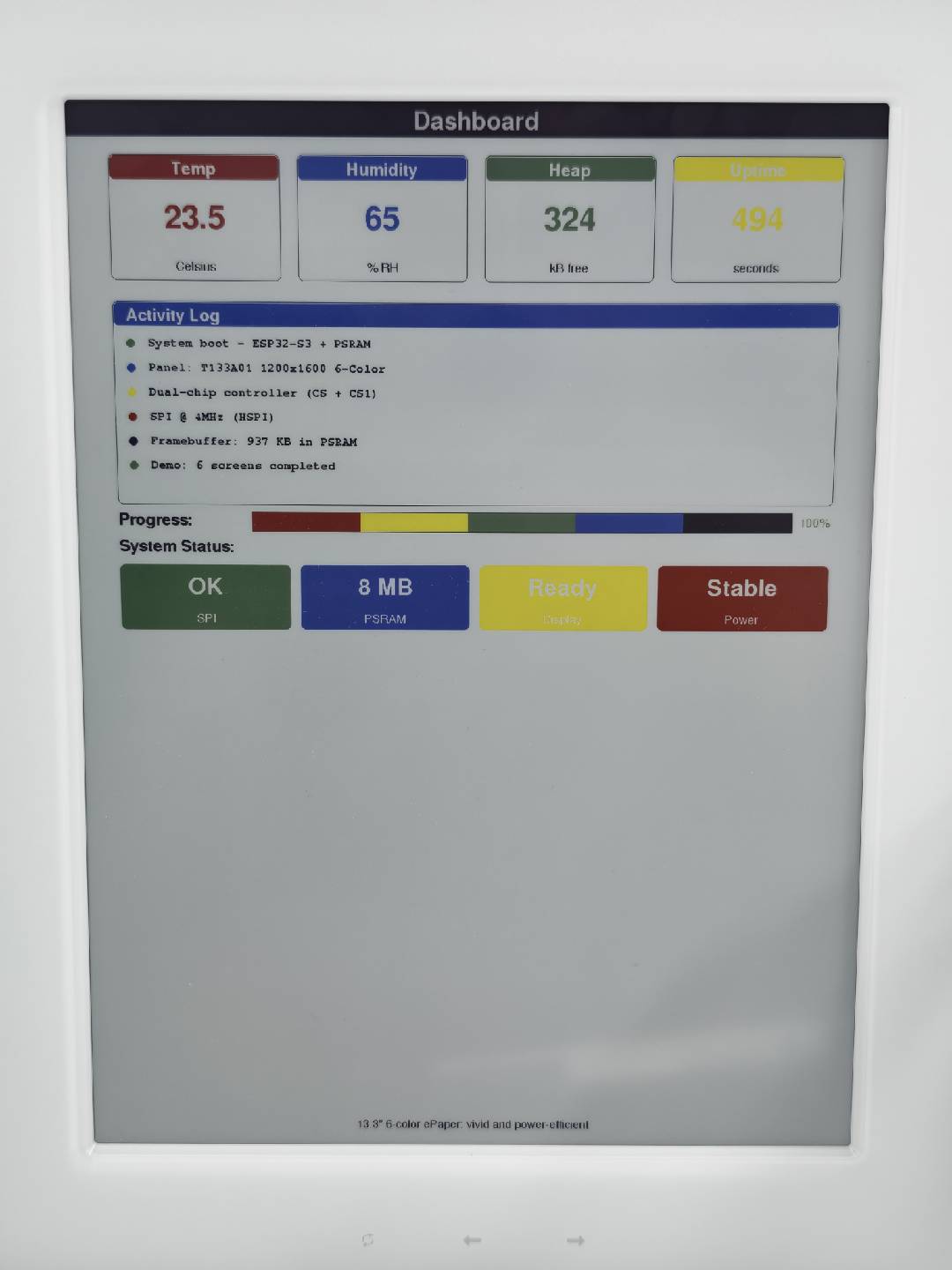
El código fuente completo para el ejemplo E1004 (incluyendo las 6 pantallas de demostración con implementaciones completas para Splash, Color Palette, Typography, Geometry, Patterns y Dashboard) está disponible en el repositorio en Seeed_GxEPD2/examples/GxEPD2_reTerminal_E1004/. El ejemplo incluye tarjetas de color, barras de progreso multicolor, tarjetas de estado y registros de actividad optimizados para la gran pantalla de 13,3" y 6 colores.
Uso de la biblioteca GxEPD2 para visualización en escala de grises multinivel
Además de los modos estándar en blanco y negro y de 6 colores, algunas pantallas reTerminal admiten renderizado en escala de grises multinivel. La biblioteca Seeed_GxEPD2 incluye ejemplos dedicados de escala de grises que omiten los controladores normales GxEPD2_BW / GxEPD2_7C y, en su lugar, controlan directamente el controlador de pantalla usando formas de onda LUT personalizadas, aprovechando al mismo tiempo Adafruit_GFX para el dibujo.
- reTerminal E1001 (7.5" B&W): El controlador UC8179 admite un modo de escala de grises de 4 niveles mediante tablas LUT especializadas VCOM/WW/KW/WK/KK. Se utiliza un framebuffer de 2 bpp (96 KB) y cada píxel puede ser negro, gris oscuro, gris claro o blanco.
- reTerminal E1003 (10.3" Monochrome): El controlador IT8951 admite de forma nativa escala de grises de 16 niveles mediante su modo de forma de onda GC16. Se asigna un framebuffer de 4 bpp (~1,25 MB) en la PSRAM y cada píxel puede representar uno de 16 niveles de gris.
- reTerminal E1001 (4-Gray)
- reTerminal E1003 (16-Gray)
Programación de reTerminal E1001 — escala de grises de 4 niveles
El controlador UC8179 del E1001 se puede cambiar de su modo normal de 1 bit a un modo de escala de grises de 4 niveles cargando tablas LUT personalizadas (VCOM, LUTWW, LUTKW, LUTWK, LUTKK). Este ejemplo crea un Gray4Canvas (2 bpp, 96 KB) y utiliza Adafruit_GFX para el dibujo, luego carga dos planos de bits al controlador para el renderizado en escala de grises.
Después de instalar la biblioteca Seeed_GxEPD2, puedes encontrar este ejemplo en el IDE de Arduino a través de File > Examples > Seeed_GxEPD2 > GxEPD2_reTerminal_E1001_Gray4, o localizarlo manualmente en Seeed_GxEPD2/examples/GxEPD2_reTerminal_E1001_Gray4/GxEPD2_reTerminal_E1001_Gray4.ino.Haz clic aquí para ver el código completo
#include <SPI.h>
#include <Adafruit_GFX.h>
#include <Fonts/FreeMonoBold9pt7b.h>
#include <Fonts/FreeMonoBold12pt7b.h>
#include <Fonts/FreeSansBold18pt7b.h>
#include <Fonts/FreeSansBold12pt7b.h>
#include <Fonts/FreeSans9pt7b.h>

// ===== Pin mapping (E1001) =====
#define EPD_SCK_PIN   7
#define EPD_MOSI_PIN  9
#define EPD_CS_PIN    10
#define EPD_DC_PIN    11
#define EPD_RES_PIN   12
#define EPD_BUSY_PIN  13

#define EPD_W  800
#define EPD_H  480

SPIClass hspi(HSPI);
SPISettings spiSet(2000000, MSBFIRST, SPI_MODE0);

// Gray levels
#define G_BLACK       0
#define G_DARK_GRAY   1
#define G_LIGHT_GRAY  2
#define G_WHITE       3

// UC8179 gray LUT tables (verbatim from Seeed_GFX UC8179_Defines.h)
// Each LUT is 7 phases x 6 bytes = 42 bytes.
static const uint8_t LUT_VCOM_GRAY[] = {
  0x00,0x00,0x06,0x08,0x07,0x01,
  0x00,0x06,0x0A,0x0B,0x0A,0x01,
  0x00,0x03,0x03,0x00,0x00,0x03,
  0x00,0x05,0x09,0x06,0x06,0x01,
  0x00,0x02,0x02,0x0A,0x0A,0x01,
  0x00,0x0A,0x11,0x06,0x07,0x01,
  0x00,0x02,0x01,0x02,0x01,0x01,
};

static const uint8_t LUT_WW_GRAY[] = {
  0x15,0x00,0x06,0x08,0x07,0x01,
  0x54,0x06,0x0A,0x0B,0x0A,0x01,
  0x90,0x03,0x03,0x00,0x00,0x03,
  0x2A,0x05,0x09,0x06,0x06,0x01,
  0xAA,0x02,0x02,0x0A,0x0A,0x01,
  0x00,0x0A,0x11,0x06,0x07,0x01,
  0x28,0x02,0x01,0x02,0x01,0x01,
};

static const uint8_t LUT_KW_GRAY[] = {
  0x2A,0x00,0x06,0x08,0x07,0x01,
  0x59,0x06,0x0A,0x0B,0x0A,0x01,
  0x90,0x03,0x03,0x00,0x00,0x03,
  0x5A,0x05,0x09,0x06,0x06,0x01,
  0xA8,0x02,0x02,0x0A,0x0A,0x01,
  0x45,0x0A,0x11,0x06,0x07,0x01,
  0xA8,0x02,0x01,0x02,0x01,0x01,
};

static const uint8_t LUT_WK_GRAY[] = {
  0x16,0x00,0x06,0x08,0x07,0x01,
  0xA0,0x06,0x0A,0x0B,0x0A,0x01,
  0x90,0x03,0x03,0x00,0x00,0x03,
  0x99,0x05,0x09,0x06,0x06,0x01,
  0xA0,0x02,0x02,0x0A,0x0A,0x01,
  0x40,0x0A,0x11,0x06,0x07,0x01,
  0x20,0x02,0x01,0x02,0x01,0x01,
};

static const uint8_t LUT_KK_GRAY[] = {
  0x26,0x00,0x06,0x08,0x07,0x01,
  0x6A,0x06,0x0A,0x0B,0x0A,0x01,
  0x90,0x03,0x03,0x00,0x00,0x03,
  0x65,0x05,0x09,0x06,0x06,0x01,
  0x50,0x02,0x02,0x0A,0x0A,0x01,
  0x10,0x0A,0x11,0x06,0x07,0x01,
  0x10,0x02,0x01,0x02,0x01,0x01,
};

static const uint8_t CMD_USER_GRAY[] = {
  0x17, 0x3F, 0x3F, 0x07, 0x06, 0x12,
};

// ============================================================
// 4-level grayscale canvas (2bpp)
// ============================================================
class Gray4Canvas : public Adafruit_GFX
{
public:
  Gray4Canvas(uint16_t w, uint16_t h) : Adafruit_GFX(w, h), _buf(nullptr) {}

  bool begin()
  {
    uint32_t sz = uint32_t(_width) * _height / 4;
    _buf = (uint8_t*)malloc(sz);
    if (_buf) memset(_buf, 0xFF, sz); // fill white (0b11 = 3 = white)
    return _buf != nullptr;
  }

  void drawPixel(int16_t x, int16_t y, uint16_t color) override
  {
    if (!_buf) return;
    if (x < 0 || x >= width() || y < 0 || y >= height()) return;

    int16_t rx = x, ry = y;
    switch (getRotation()) {
      case 1: rx = _width - 1 - y; ry = x; break;
      case 2: rx = _width - 1 - x; ry = _height - 1 - y; break;
      case 3: rx = y; ry = _height - 1 - x; break;
    }

    uint8_t g = color & 0x03;
    uint32_t idx = uint32_t(ry) * (_width / 4) + rx / 4;
    uint8_t shift = (3 - (rx & 3)) * 2;
    _buf[idx] = (_buf[idx] & ~(0x03 << shift)) | (g << shift);
  }

  void fillScreen(uint16_t color) override
  {
    if (!_buf) return;
    uint8_t g = color & 0x03;
    uint8_t fill = (g << 6) | (g << 4) | (g << 2) | g;
    memset(_buf, fill, uint32_t(_width) * _height / 4);
  }

  uint8_t getPixel(int16_t x, int16_t y) const
  {
    if (!_buf || x < 0 || x >= _width || y < 0 || y >= _height) return 0;
    uint32_t idx = uint32_t(y) * (_width / 4) + x / 4;
    uint8_t shift = (3 - (x & 3)) * 2;
    return (_buf[idx] >> shift) & 0x03;
  }

  uint8_t* buffer() { return _buf; }

private:
  uint8_t* _buf;
};

Gray4Canvas canvas(EPD_W, EPD_H);

// ============================================================
// UC8179 SPI helpers
// ============================================================
void checkBusy() {
  delay(10);
  while (!digitalRead(EPD_BUSY_PIN)) delay(10);
}

void writeCommand(uint8_t cmd) {
  hspi.beginTransaction(spiSet);
  digitalWrite(EPD_DC_PIN, LOW);
  digitalWrite(EPD_CS_PIN, LOW);
  hspi.transfer(cmd);
  digitalWrite(EPD_CS_PIN, HIGH);
  digitalWrite(EPD_DC_PIN, HIGH);
  hspi.endTransaction();
}

void writeData(uint8_t data) {
  hspi.beginTransaction(spiSet);
  digitalWrite(EPD_CS_PIN, LOW);
  hspi.transfer(data);
  digitalWrite(EPD_CS_PIN, HIGH);
  hspi.endTransaction();
}

void writeLUT(uint8_t cmd, const uint8_t* lut, uint16_t len) {
  writeCommand(cmd);
  for (uint16_t i = 0; i < len; i++) writeData(lut[i]);
}

// ============================================================
// UC8179 gray mode initialization
// ============================================================
void initGrayMode()
{
  // Hardware reset
  digitalWrite(EPD_RES_PIN, LOW); delay(10);
  digitalWrite(EPD_RES_PIN, HIGH); delay(10);
  checkBusy();

  // Power setting (0x01)
  writeCommand(0x01);
  writeData(0x07);
  writeData(CMD_USER_GRAY[0]);
  writeData(CMD_USER_GRAY[1]);
  writeData(CMD_USER_GRAY[2]);
  writeData(CMD_USER_GRAY[3]);

  // PLL (0x30)
  writeCommand(0x30);
  writeData(CMD_USER_GRAY[4]);

  // VCOM DC (0x82)
  writeCommand(0x82);
  writeData(CMD_USER_GRAY[5]);

  // Booster (0x06)
  writeCommand(0x06);
  writeData(0x27);
  writeData(0x27);
  writeData(0x28);
  writeData(0x17);

  // Power ON (0x04)
  writeCommand(0x04);
  delay(100);
  checkBusy();

  // Panel Setting (0x00)
  writeCommand(0x00);
  writeData(0x3F);

  // Power saving (0xE3)
  writeCommand(0xE3);
  writeData(0x88);

  // VCOM and Data interval (0x50)
  writeCommand(0x50);
  writeData(0x10);
  writeData(0x07);

  // PLL setting (0x52)
  writeCommand(0x52);
  writeData(0x00);

  // Resolution (0x61)
  writeCommand(0x61);
  writeData(EPD_W >> 8);
  writeData(EPD_W & 0xFF);
  writeData(EPD_H >> 8);
  writeData(EPD_H & 0xFF);

  // Write LUTs for gray mode. CRITICAL ordering — UC8179:
  //   0x20 = LUTC  (VCOM)   ← must be present
  //   0x21 = LUTWW (W -> W)
  //   0x22 = LUTKW (K -> W)
  //   0x23 = LUTWK (W -> K)
  //   0x24 = LUTKK (K -> K)
  writeLUT(0x20, LUT_VCOM_GRAY, sizeof(LUT_VCOM_GRAY));
  checkBusy();
  writeLUT(0x21, LUT_WW_GRAY,   sizeof(LUT_WW_GRAY));
  checkBusy();
  writeLUT(0x22, LUT_KW_GRAY,   sizeof(LUT_KW_GRAY));
  checkBusy();
  writeLUT(0x23, LUT_WK_GRAY,   sizeof(LUT_WK_GRAY));
  writeLUT(0x24, LUT_KK_GRAY,   sizeof(LUT_KK_GRAY));

  Serial.println(F("[Gray4] UC8179 gray mode init done"));
}

// ============================================================
// Upload 2bpp canvas to UC8179 as two bit-planes.
// ============================================================
void uploadGray4Frame()
{
  const uint32_t bytesPerRow = EPD_W / 4; // 200 bytes (2bpp, 4 pixels/byte)

  // ---- Bit plane → DTM1 (command 0x10) ----
  writeCommand(0x10);
  hspi.beginTransaction(spiSet);
  digitalWrite(EPD_CS_PIN, LOW);
  for (uint16_t row = 0; row < EPD_H; row++) {
    const uint8_t* rp = canvas.buffer() + uint32_t(row) * bytesPerRow;
    for (uint16_t col8 = 0; col8 < EPD_W / 8; col8++) {
      uint8_t out = 0;
      for (uint8_t bit = 0; bit < 8; bit++) {
        uint16_t px = col8 * 8 + bit;
        uint32_t idx = px / 4;
        uint8_t shift = (3 - (px & 3)) * 2;
        uint8_t gray = 3 - ((rp[idx] >> shift) & 0x03);  // INVERT
        if (gray & 0x01) out |= (0x80 >> bit);
      }
      hspi.transfer(out);
    }
  }
  digitalWrite(EPD_CS_PIN, HIGH);
  hspi.endTransaction();

  // ---- Bit plane → DTM2 (command 0x13) ----
  writeCommand(0x13);
  hspi.beginTransaction(spiSet);
  digitalWrite(EPD_CS_PIN, LOW);
  for (uint16_t row = 0; row < EPD_H; row++) {
    const uint8_t* rp = canvas.buffer() + uint32_t(row) * bytesPerRow;
    for (uint16_t col8 = 0; col8 < EPD_W / 8; col8++) {
      uint8_t out = 0;
      for (uint8_t bit = 0; bit < 8; bit++) {
        uint16_t px = col8 * 8 + bit;
        uint32_t idx = px / 4;
        uint8_t shift = (3 - (px & 3)) * 2;
        uint8_t gray = 3 - ((rp[idx] >> shift) & 0x03);  // INVERT
        if (gray & 0x02) out |= (0x80 >> bit);
      }
      hspi.transfer(out);
    }
  }
  digitalWrite(EPD_CS_PIN, HIGH);
  hspi.endTransaction();

  Serial.println(F("[Gray4] Frame uploaded (2 bit planes)"));
}

void refreshDisplay()
{
  unsigned long t0 = millis();
  writeCommand(0x12); // Display Refresh
  delay(100);
  checkBusy();
  Serial.printf("[Gray4] Refresh %lu ms\n", millis() - t0);
}

void sleepDisplay()
{
  writeCommand(0x02); // Power OFF
  checkBusy();
  writeCommand(0x07); // Deep sleep
  writeData(0xA5);
}

// ============================================================
// Demo drawing
// ============================================================
void drawCenteredText(const char* text, int16_t y, const GFXfont* font, uint8_t gray)
{
  canvas.setFont(font);
  canvas.setTextColor(gray);
  int16_t tbx, tby; uint16_t tbw, tbh;
  canvas.getTextBounds(text, 0, 0, &tbx, &tby, &tbw, &tbh);
  canvas.setCursor((EPD_W - tbw) / 2 - tbx, y);
  canvas.print(text);
}

void showGrayscaleDemo()
{
  Serial.println(F("[Gray4] Drawing demo..."));
  canvas.fillScreen(G_WHITE);

  // Title bar
  canvas.fillRect(0, 0, EPD_W, 40, G_BLACK);
  drawCenteredText("4-Level Grayscale Demo - E1001", 30, &FreeMonoBold12pt7b, G_WHITE);

  // 4 large gray bands
  int bandH = 70, startY = 55;
  const char* labels[] = {"Gray 0: Black", "Gray 1: Dark Gray", "Gray 2: Light Gray", "Gray 3: White"};
  for (int i = 0; i < 4; i++) {
    int y = startY + i * (bandH + 8);
    canvas.fillRect(30, y, EPD_W - 60, bandH, i);
    uint8_t textGray = (i < 2) ? G_WHITE : G_BLACK;
    canvas.setFont(&FreeSansBold12pt7b);
    canvas.setTextColor(textGray);
    canvas.setCursor(60, y + bandH / 2 + 8);
    canvas.print(labels[i]);
  }

  // Concentric gray circles
  int areaTop = startY + 4 * (bandH + 8);
  int areaBot = EPD_H - 30;
  int cy = (areaTop + areaBot) / 2;
  int cx = EPD_W - 80;
  canvas.setFont(&FreeMonoBold9pt7b);
  canvas.setTextColor(G_BLACK);
  canvas.setCursor(30, cy - 6);
  canvas.print("Concentric gray circles");
  canvas.setCursor(30, cy + 14);
  canvas.print("(black / dark / light / white)");
  canvas.fillCircle(cx, cy, 38, G_BLACK);
  canvas.fillCircle(cx, cy, 28, G_DARK_GRAY);
  canvas.fillCircle(cx, cy, 18, G_LIGHT_GRAY);
  canvas.fillCircle(cx, cy,  9, G_WHITE);

  // Footer
  canvas.fillRect(0, EPD_H - 30, EPD_W, 30, G_BLACK);
  drawCenteredText("UC8179 4-gray LUT mode | E1001", EPD_H - 8, &FreeMonoBold9pt7b, G_WHITE);

  Serial.println(F("[Gray4] Uploading..."));
  uploadGray4Frame();
  refreshDisplay();
  Serial.println(F("[Gray4] Done."));
}

// ============================================================
void setup()
{
  Serial.begin(115200);
  delay(200);
  Serial.println(F("[E1001 Gray4] Starting..."));

  pinMode(EPD_CS_PIN, OUTPUT);  digitalWrite(EPD_CS_PIN, HIGH);
  pinMode(EPD_DC_PIN, OUTPUT);  digitalWrite(EPD_DC_PIN, HIGH);
  pinMode(EPD_RES_PIN, OUTPUT); digitalWrite(EPD_RES_PIN, HIGH);
  pinMode(EPD_BUSY_PIN, INPUT);

  hspi.begin(EPD_SCK_PIN, -1, EPD_MOSI_PIN, -1);

  if (!canvas.begin()) {
    Serial.println(F("[Gray4] FATAL: alloc failed (96 KB)"));
    while (true) delay(1000);
  }
  Serial.printf("[Gray4] Canvas OK (%lu bytes)\n", (unsigned long)(EPD_W * EPD_H / 4));

  initGrayMode();
  showGrayscaleDemo();
  sleepDisplay();
}

void loop() {}
La siguiente figura muestra el efecto de visualización real del ejemplo de escala de grises de 4 niveles del E1001:
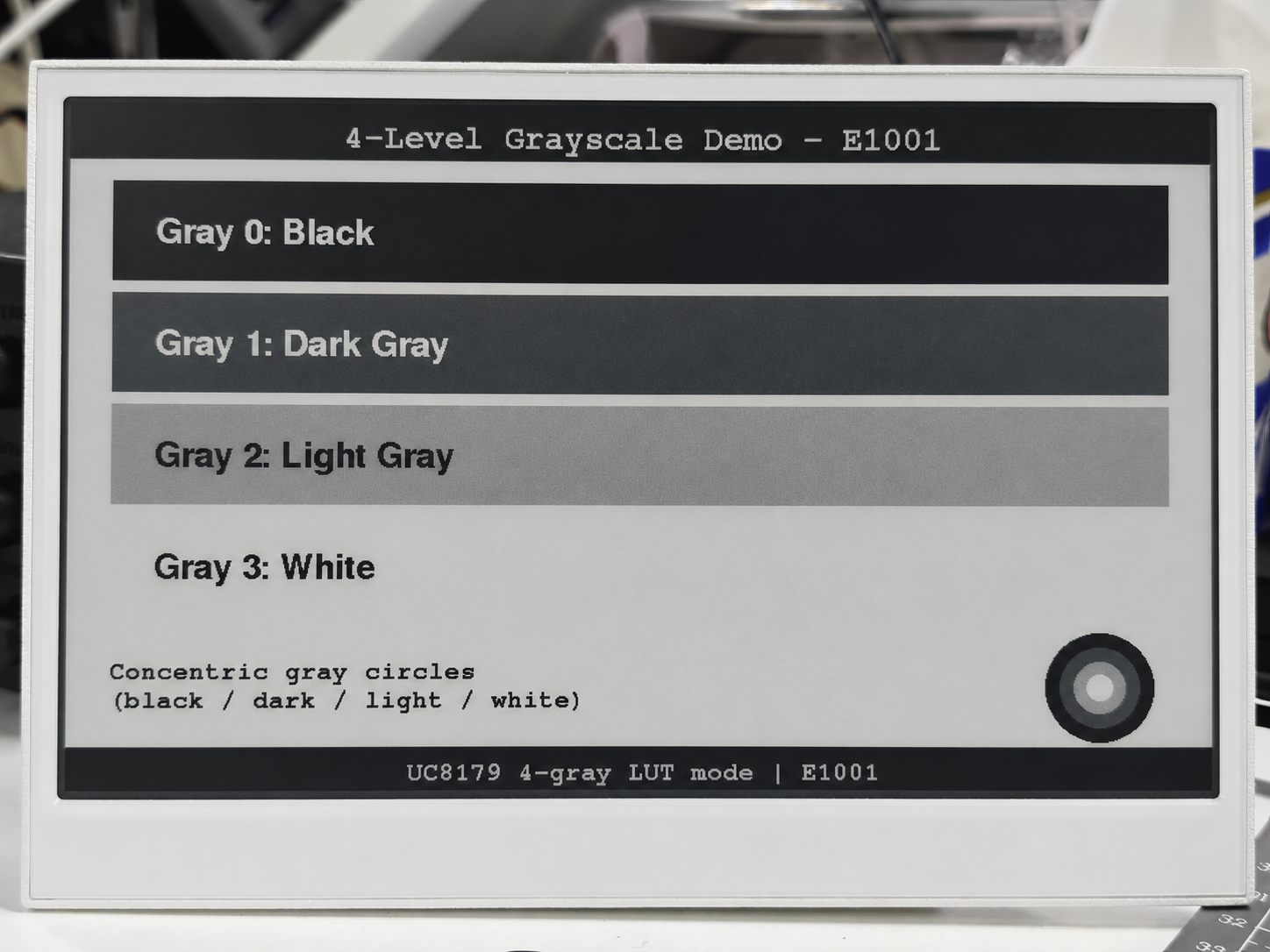
Programación del reTerminal E1003 — escala de grises de 16 niveles
El controlador IT8951 del E1003 admite de forma nativa una escala de grises de 16 niveles mediante su modo de forma de onda GC16. Este ejemplo asigna un framebuffer de 4bpp (~1,25 MB) en la PSRAM y utiliza Adafruit_GFX para dibujar a través de una clase Gray16Canvas, luego carga el fotograma como datos 8BPP al IT8951 para la actualización GC16.
Este ejemplo requiere que OPI PSRAM esté habilitada en el IDE de Arduino: Tools > PSRAM > OPI PSRAM. El framebuffer de ~1,25 MB reside en la PSRAM.
Después de instalar la biblioteca Seeed_GxEPD2, puedes encontrar este ejemplo en el IDE de Arduino a través de File > Examples > Seeed_GxEPD2 > GxEPD2_reTerminal_E1003_Gray16, o localizarlo manualmente en Seeed_GxEPD2/examples/GxEPD2_reTerminal_E1003_Gray16/GxEPD2_reTerminal_E1003_Gray16.ino.Haz clic aquí para ver el código completo
#include <SPI.h>
#include <Adafruit_GFX.h>
#include <Fonts/FreeMonoBold9pt7b.h>
#include <Fonts/FreeMonoBold12pt7b.h>

// ===== Pin mapping (E1003) =====
#define EPD_SCK_PIN     7
#define EPD_MISO_PIN    8
#define EPD_MOSI_PIN    9
#define EPD_CS_PIN      10
#define EPD_BUSY_PIN    13  // HRDY
#define EPD_TFT_ENABLE  11
#define EPD_ITE_ENABLE  21

// Panel geometry
#define EPD_W  1872
#define EPD_H  1404

SPIClass hspi(HSPI);
SPISettings spiSet(10000000, MSBFIRST, SPI_MODE0);

// IT8951 commands
#define CMD_SYS_RUN       0x0001
#define CMD_STANDBY       0x0002
#define CMD_SLEEP         0x0003
#define CMD_REG_RD        0x0010
#define CMD_REG_WR        0x0011
#define CMD_LD_IMG_AREA   0x0021
#define CMD_LD_IMG_END    0x0022
#define CMD_DPY_AREA      0x0034
#define REG_LISAR         0x0208

#define IT8951_8BPP        3
#define IT8951_B_ENDIAN    1
#define IT8951_ROTATE_0    0

#define DBG Serial0

// ============================================================
// Minimal 16-level grayscale canvas (4bpp, PSRAM-backed)
// ============================================================
class Gray16Canvas : public Adafruit_GFX
{
public:
  Gray16Canvas(uint16_t w, uint16_t h) : Adafruit_GFX(w, h), _buf(nullptr) {}

  bool begin()
  {
    uint32_t sz = uint32_t(_width) * _height / 2;
#if defined(ESP32)
    _buf = (uint8_t*)heap_caps_malloc(sz, MALLOC_CAP_SPIRAM | MALLOC_CAP_8BIT);
#else
    _buf = (uint8_t*)malloc(sz);
#endif
    return _buf != nullptr;
  }

  void drawPixel(int16_t x, int16_t y, uint16_t color) override
  {
    if (!_buf) return;
    if (x < 0 || x >= _width || y < 0 || y >= _height) return;
    switch (getRotation()) {
      case 1: { int16_t t = x; x = _width - 1 - y; y = t; break; }
      case 2: x = _width - 1 - x; y = _height - 1 - y; break;
      case 3: { int16_t t = x; x = y; y = _height - 1 - t; break; }
    }
    uint8_t g = color & 0x0F;
    uint32_t idx = uint32_t(y) * (_width / 2) + x / 2;
    if (x & 1) _buf[idx] = (_buf[idx] & 0xF0) | g;
    else       _buf[idx] = (_buf[idx] & 0x0F) | (g << 4);
  }

  void fillScreen(uint16_t color) override
  {
    if (!_buf) return;
    uint8_t g = color & 0x0F;
    memset(_buf, (g << 4) | g, uint32_t(_width) * _height / 2);
  }

  uint8_t getPixel4bpp(int16_t x, int16_t y) const
  {
    if (!_buf || x < 0 || x >= _width || y < 0 || y >= _height) return 0;
    uint32_t idx = uint32_t(y) * (_width / 2) + x / 2;
    return (x & 1) ? (_buf[idx] & 0x0F) : ((_buf[idx] >> 4) & 0x0F);
  }

  uint8_t* buffer() { return _buf; }

private:
  uint8_t* _buf;
};

Gray16Canvas canvas(EPD_W, EPD_H);

// IT8951 device info
uint32_t imgBufAddr = 0;

// ============================================================
// IT8951 SPI helpers
// ============================================================
void waitHRDY() { while (digitalRead(EPD_BUSY_PIN) == LOW) delay(1); }

uint16_t xfer16(uint16_t v) {
  uint16_t r = hspi.transfer16(v);
  return r;
}

void writeCmd16(uint16_t cmd) {
  waitHRDY();
  hspi.beginTransaction(spiSet);
  digitalWrite(EPD_CS_PIN, LOW);
  xfer16(0x6000);
  waitHRDY();
  xfer16(cmd);
  digitalWrite(EPD_CS_PIN, HIGH);
  hspi.endTransaction();
}

void writeData16(uint16_t data) {
  waitHRDY();
  hspi.beginTransaction(spiSet);
  digitalWrite(EPD_CS_PIN, LOW);
  xfer16(0x0000);
  waitHRDY();
  xfer16(data);
  digitalWrite(EPD_CS_PIN, HIGH);
  hspi.endTransaction();
}

uint16_t readData16() {
  waitHRDY();
  hspi.beginTransaction(spiSet);
  digitalWrite(EPD_CS_PIN, LOW);
  xfer16(0x1000);
  waitHRDY();
  xfer16(0);          // dummy
  uint16_t v = xfer16(0);
  digitalWrite(EPD_CS_PIN, HIGH);
  hspi.endTransaction();
  return v;
}

void writeReg(uint16_t reg, uint16_t val) {
  writeCmd16(CMD_REG_WR);
  writeData16(reg);
  writeData16(val);
}

uint16_t readReg(uint16_t reg) {
  writeCmd16(CMD_REG_RD);
  writeData16(reg);
  return readData16();
}

void readDevInfo() {
  writeCmd16(0x0302);
  uint16_t buf[20];
  waitHRDY();
  hspi.beginTransaction(spiSet);
  digitalWrite(EPD_CS_PIN, LOW);
  xfer16(0x1000);
  waitHRDY();
  xfer16(0);
  for (int i = 0; i < 20; i++) buf[i] = xfer16(0);
  digitalWrite(EPD_CS_PIN, HIGH);
  hspi.endTransaction();
  imgBufAddr = (uint32_t(buf[3]) << 16) | buf[2];
  DBG.printf("[IT8951] panel %ux%u, imgBuf=0x%08lX\n", buf[0], buf[1], imgBufAddr);
}

void setVCOM(uint16_t mV) {
  writeCmd16(0x0039);
  writeData16(0x0001);
  writeData16(mV);
}

void setTemperature(uint16_t t) {
  writeCmd16(0x0040);
  writeData16(0x0001);
  writeData16(t);
}

// ============================================================
// Upload 4bpp framebuffer to IT8951 as 8BPP, X-mirrored
// ============================================================
void uploadGray16Frame()
{
  writeReg(REG_LISAR,     (uint16_t)(imgBufAddr & 0xFFFF));
  writeReg(REG_LISAR + 2, (uint16_t)(imgBufAddr >> 16));

  setTemperature(16);

  uint16_t args[5];
  args[0] = (IT8951_B_ENDIAN << 8) | (IT8951_8BPP << 4) | IT8951_ROTATE_0;
  args[1] = 0;
  args[2] = 0;
  args[3] = EPD_W;
  args[4] = EPD_H;
  writeCmd16(CMD_LD_IMG_AREA);
  for (int i = 0; i < 5; i++) writeData16(args[i]);

  unsigned long t0 = millis();
  hspi.beginTransaction(spiSet);
  digitalWrite(EPD_CS_PIN, LOW);
  waitHRDY();
  xfer16(0x0000);
  waitHRDY();

  const uint16_t WB = EPD_W / 2;
  for (uint16_t row = 0; row < EPD_H; row++) {
    const uint8_t* rp = canvas.buffer() + uint32_t(row) * WB;
    // X-mirror: send bytes right-to-left, nibbles LSB-first within each byte
    for (int16_t col = WB - 1; col >= 0; col--) {
      uint8_t byte_val = rp[col];
      uint8_t lo = byte_val & 0x0F;
      uint8_t hi = (byte_val >> 4) & 0x0F;
      hspi.transfer(lo * 17);  // low nibble = right pixel (sent first due to X-mirror)
      hspi.transfer(hi * 17);  // high nibble = left pixel
    }
    if ((row & 0x3F) == 0) yield();
  }

  digitalWrite(EPD_CS_PIN, HIGH);
  hspi.endTransaction();

  writeCmd16(CMD_LD_IMG_END);
  waitHRDY();

  DBG.printf("[Gray16] upload %lu ms\n", millis() - t0);
}

void displayRefreshGC16()
{
  unsigned long t0 = millis();
  writeCmd16(CMD_DPY_AREA);
  waitHRDY(); writeData16(0);
  waitHRDY(); writeData16(0);
  waitHRDY(); writeData16(EPD_W);
  waitHRDY(); writeData16(EPD_H);
  waitHRDY(); writeData16(2);  // mode 2 = GC16

  while (digitalRead(EPD_BUSY_PIN) == LOW) {
    if (millis() - t0 > 15000) break;
    delay(100);
  }
  DBG.printf("[Gray16] refresh %lu ms\n", millis() - t0);
}

// ============================================================
// Demo drawing functions
// ============================================================

// Gray colors 0-15 (0=black, 15=white)
#define G_BLACK   0
#define G_WHITE  15

void drawCenteredText(const char* text, int16_t y, const GFXfont* font, uint8_t gray)
{
  canvas.setFont(font);
  canvas.setTextColor(gray);
  int16_t tbx, tby; uint16_t tbw, tbh;
  canvas.getTextBounds(text, 0, 0, &tbx, &tby, &tbw, &tbh);
  canvas.setCursor((EPD_W - tbw) / 2 - tbx, y);
  canvas.print(text);
}

void showGrayscaleDemo()
{
  DBG.println(F("[Gray16] Drawing grayscale demo..."));
  canvas.fillScreen(G_WHITE);

  // Title
  canvas.fillRect(0, 0, EPD_W, 60, G_BLACK);
  drawCenteredText("16-Level Grayscale Demo - E1003", 45, &FreeMonoBold12pt7b, G_WHITE);

  // 16 horizontal gray bands
  int bandH = 60, startY = 80;
  canvas.setFont(&FreeMonoBold9pt7b);
  for (int i = 0; i < 16; i++) {
    int y = startY + i * bandH;
    canvas.fillRect(50, y, EPD_W - 100, bandH - 4, i);
    uint8_t textColor = (i < 8) ? 15 : 0;
    canvas.setTextColor(textColor);
    char buf[32];
    snprintf(buf, sizeof(buf), "Gray %2d  (8bpp = %3d)", i, i * 17);
    canvas.setCursor(80, y + bandH / 2 + 5);
    canvas.print(buf);
  }

  // Gradient bar (smooth)
  int gradY = startY + 16 * bandH + 20;
  canvas.setFont(&FreeMonoBold9pt7b);
  canvas.setTextColor(G_BLACK);
  canvas.setCursor(50, gradY - 5);
  canvas.print("Smooth 16-step gradient:");
  for (int x = 0; x < EPD_W - 100; x++) {
    uint8_t g = (x * 15) / (EPD_W - 101);
    canvas.drawFastVLine(50 + x, gradY + 10, 60, g);
  }
  canvas.drawRect(49, gradY + 9, EPD_W - 98, 62, G_BLACK);

  // Concentric circles with gray levels
  int cx = EPD_W / 2;
  int cy = gradY + 102;
  canvas.setTextColor(G_BLACK);
  canvas.setCursor(50, cy);
  canvas.print("Concentric gray circles:");
  cy += 35;
  for (int r = 7; r >= 0; r--) {
    int radius = 24 + r * 12;
    canvas.fillCircle(cx, cy + 45, radius, r * 2);
  }

  DBG.println(F("[Gray16] Uploading..."));
  uploadGray16Frame();
  displayRefreshGC16();
  DBG.println(F("[Gray16] Done."));
}

void setup()
{
  Serial.begin(115200);
  delay(200);
  Serial.println(F("[E1003 Gray16] Starting..."));

  pinMode(EPD_CS_PIN, OUTPUT);
  digitalWrite(EPD_CS_PIN, HIGH);
  pinMode(EPD_BUSY_PIN, INPUT);
  pinMode(EPD_TFT_ENABLE, OUTPUT);
  digitalWrite(EPD_TFT_ENABLE, HIGH);
  pinMode(EPD_ITE_ENABLE, OUTPUT);
  digitalWrite(EPD_ITE_ENABLE, HIGH);

  hspi.begin(EPD_SCK_PIN, EPD_MISO_PIN, EPD_MOSI_PIN, -1);

  delay(100);
  writeCmd16(CMD_SYS_RUN);
  delay(100);

  readDevInfo();
  setVCOM(1400);

  if (!canvas.begin()) {
    DBG.println(F("[Gray16] FATAL: PSRAM alloc failed (~1.25 MB needed)"));
    while (true) delay(1000);
  }
  DBG.printf("[Gray16] Framebuffer OK (%lu bytes)\n", (unsigned long)(EPD_W * EPD_H / 2));

  showGrayscaleDemo();
}

void loop() {}
La siguiente figura muestra el efecto de visualización real del ejemplo de escala de grises de 16 niveles del E1003:
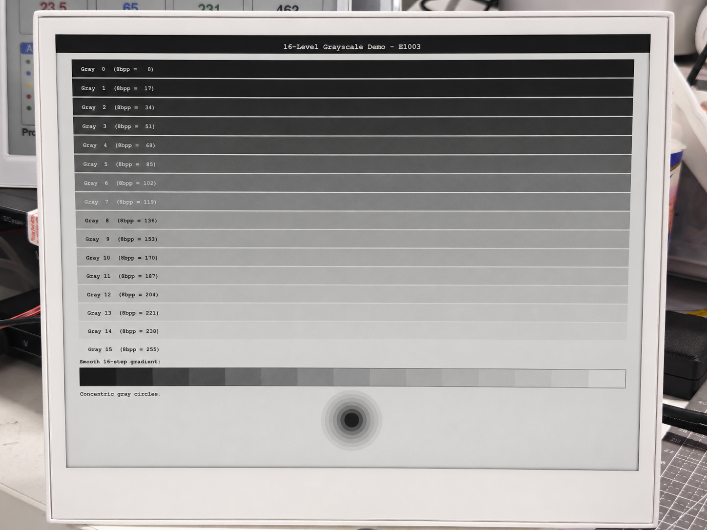
Las pantallas de ePaper tienen una velocidad de actualización relativamente lenta. Las pantallas en blanco y negro (E1001, E1003) suelen actualizarse en 1-3 segundos, mientras que las pantallas de 6 colores (E1002, E1004) pueden tardar entre 25 y 40 segundos en una actualización completa. Este comportamiento es normal y es una compensación por el consumo de energía ultra bajo y la excelente visibilidad sin retroiluminación.
Solución de problemas
P1: ¿Por qué la pantalla de ePaper del reTerminal no muestra nada ni se actualiza al ejecutar el código anterior?
Este problema puede ocurrir si has insertado una tarjeta MicroSD en el reTerminal. La razón es que la tarjeta MicroSD y la pantalla de ePaper comparten el mismo bus SPI en el reTerminal. Si se inserta una tarjeta MicroSD pero su pin de habilitación (chip select) no se gestiona correctamente, puede provocar un conflicto en el bus SPI. En concreto, la tarjeta MicroSD puede mantener la línea BUSY en alto, lo que impide que la pantalla de ePaper funcione correctamente, dando como resultado que no haya actualizaciones ni refrescos de la pantalla.
// Initialize SD Card
pinMode(SD_EN_PIN, OUTPUT);
digitalWrite(SD_EN_PIN, HIGH);
pinMode(SD_DET_PIN, INPUT_PULLUP);
Para resolver esto, debes asegurarte de que la tarjeta MicroSD esté correctamente habilitada utilizando el código proporcionado arriba. El código inicializa y habilita la tarjeta MicroSD configurando los estados correctos de los pines, lo que evita conflictos en el bus SPI y permite que tanto la tarjeta SD como la pantalla de ePaper funcionen juntas. Utiliza siempre el código de inicialización recomendado cuando uses una tarjeta MicroSD con el reTerminal para evitar este tipo de problemas.
Si la tarjeta MicroSD no se utiliza en tu proyecto, recomendamos apagar el dispositivo y retirar la tarjeta antes de ejecutar el programa de visualización. Si la tarjeta se ha insertado en el reTerminal, tendrás que añadir el código anterior para asegurarte de que la pantalla pueda mostrarse correctamente, independientemente de si estás utilizando una tarjeta MicroSD o no.
P2: ¿Por qué no puedo cargar programas en el reTerminal?
Si encuentras el siguiente error al cargar un programa en el reTerminal.

Entonces, es probable que tu Arduino IDE esté configurado con una velocidad de carga excesivamente alta. Cámbiala a 115200 baudios para resolver este problema.

Soporte técnico y debate sobre el producto
Gracias por elegir nuestros productos. Estamos aquí para ofrecerte diferentes tipos de soporte y garantizar que tu experiencia con nuestros productos sea lo más fluida posible. Ofrecemos varios canales de comunicación para adaptarnos a diferentes preferencias y necesidades.