Arduino Cookbook: RTC, Low Power, Audio & Touch (reTerminal E Serie)
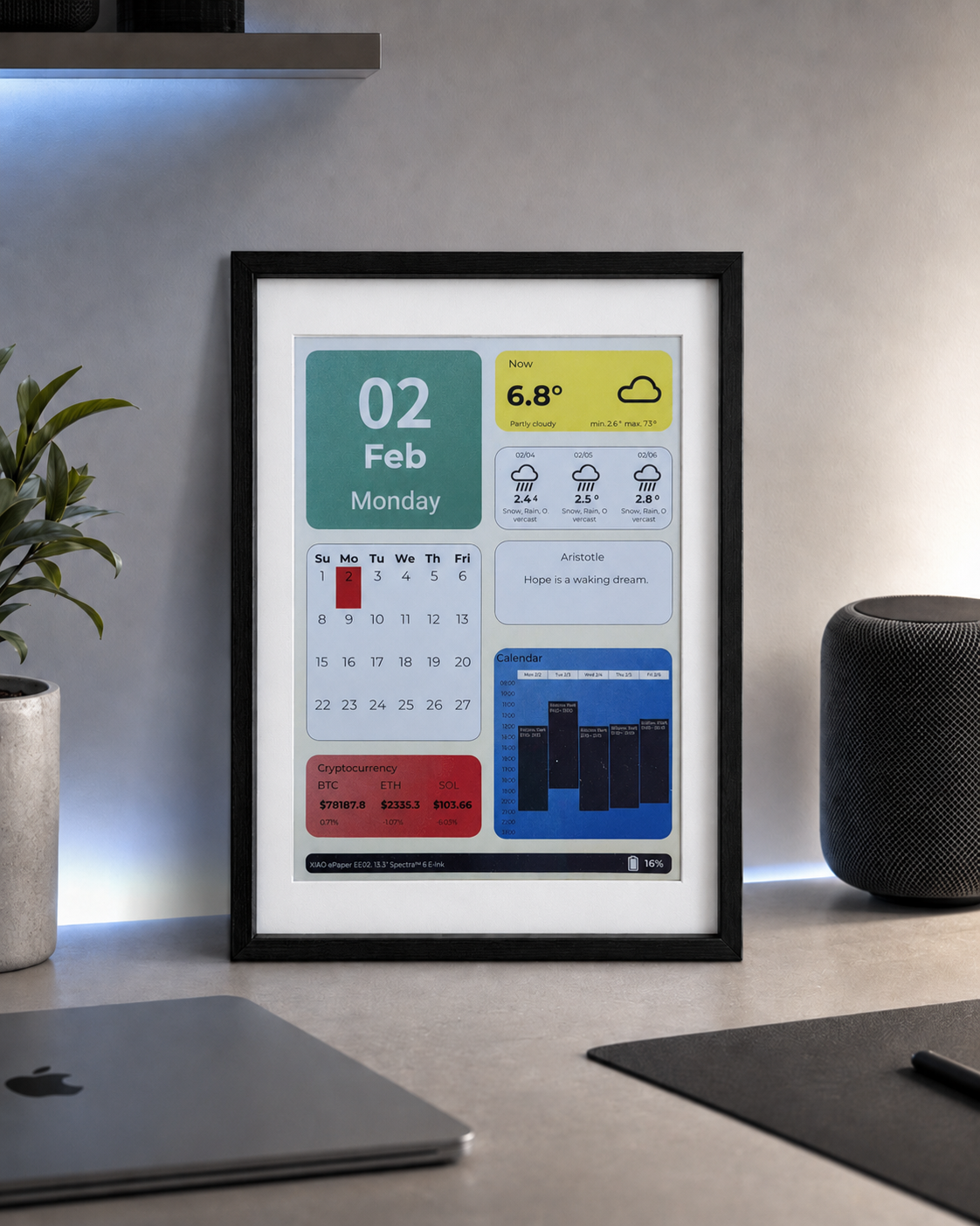
Si quieres previsualizar rápidamente los resultados del proyecto o probar el firmware de demostración básico antes de configurar un entorno de desarrollo, abre el reTerminal E-Series Firmware Hub. Puedes elegir un dispositivo compatible de la reTerminal E Serie y flashear el firmware de demostración directamente desde un navegador.
- Arduino Cookbook: ePaper Display — representación de texto, gráficos e imágenes en la pantalla de tinta electrónica.
- Arduino Cookbook: Onboard Peripherals — LED, zumbador, botones, sensor SHT4x, monitor de batería, tarjeta microSD y la canalización de imágenes de la tarjeta SD.
Introducción
Este es el segundo cookbook de periféricos para la reTerminal E Serie. Mientras que el primer cookbook de periféricos cubre los periféricos básicos de E/S (LED, zumbador, botones, SHT4x, batería, tarjeta SD), esta página profundiza en cuatro temas más avanzados:
- Reloj en tiempo real (RTC) — el chip RTC PCF8563 integrado, alimentado por una pila tipo moneda CR1220, que mantiene la hora incluso cuando se retira la batería principal.
- Modos de bajo consumo — deep sleep, light sleep y estrategias de activación por GPIO para extender la vida de la batería de días a meses.
- Micrófono PDM — captura de audio mediante el micrófono digital PDM integrado (solo E1001 / E1002 / E1003; el E1004 no tiene micrófono) y guardado de archivos WAV en la tarjeta microSD.
- Pantalla táctil — uso del panel táctil capacitivo integrado en el E1003 (modelo de 10,3") para dibujar puntos en la pantalla de tinta electrónica. Solo el E1003 tiene panel táctil.
Todos los ejemplos de este cookbook provienen del repositorio OSHW-reTerminal-Series-E-D. Los ejemplos de RTC, bajo consumo y micrófono no requieren instalar bibliotecas adicionales: todo utiliza las API integradas del ESP32. El ejemplo de táctil requiere la biblioteca Seeed_GFX.
Materiales necesarios
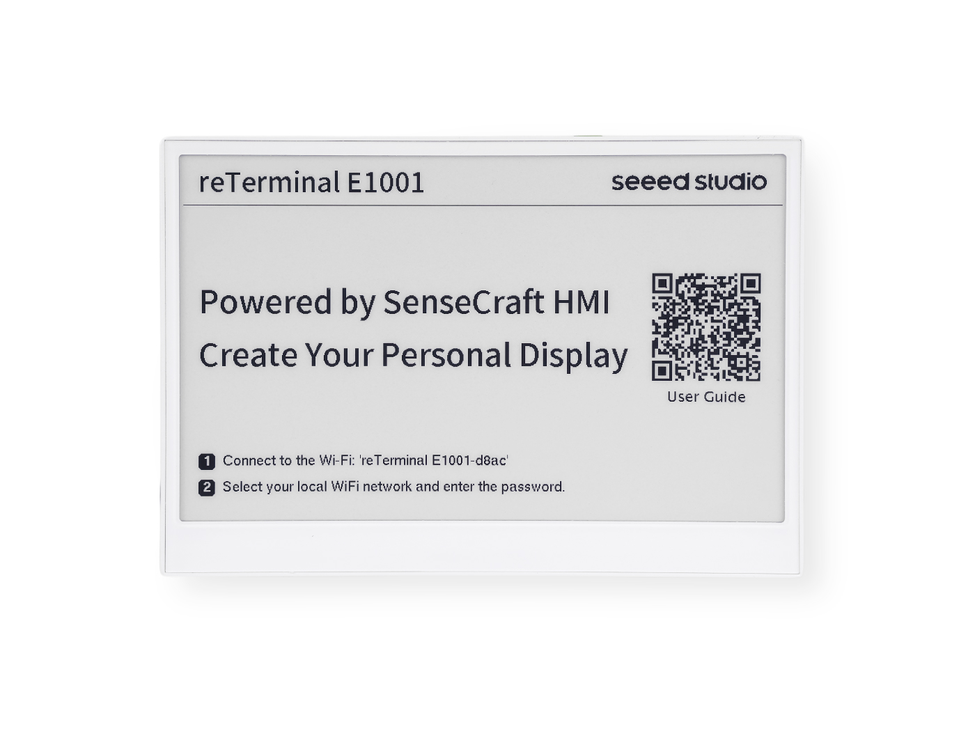
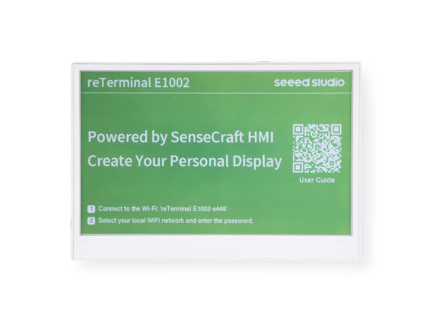
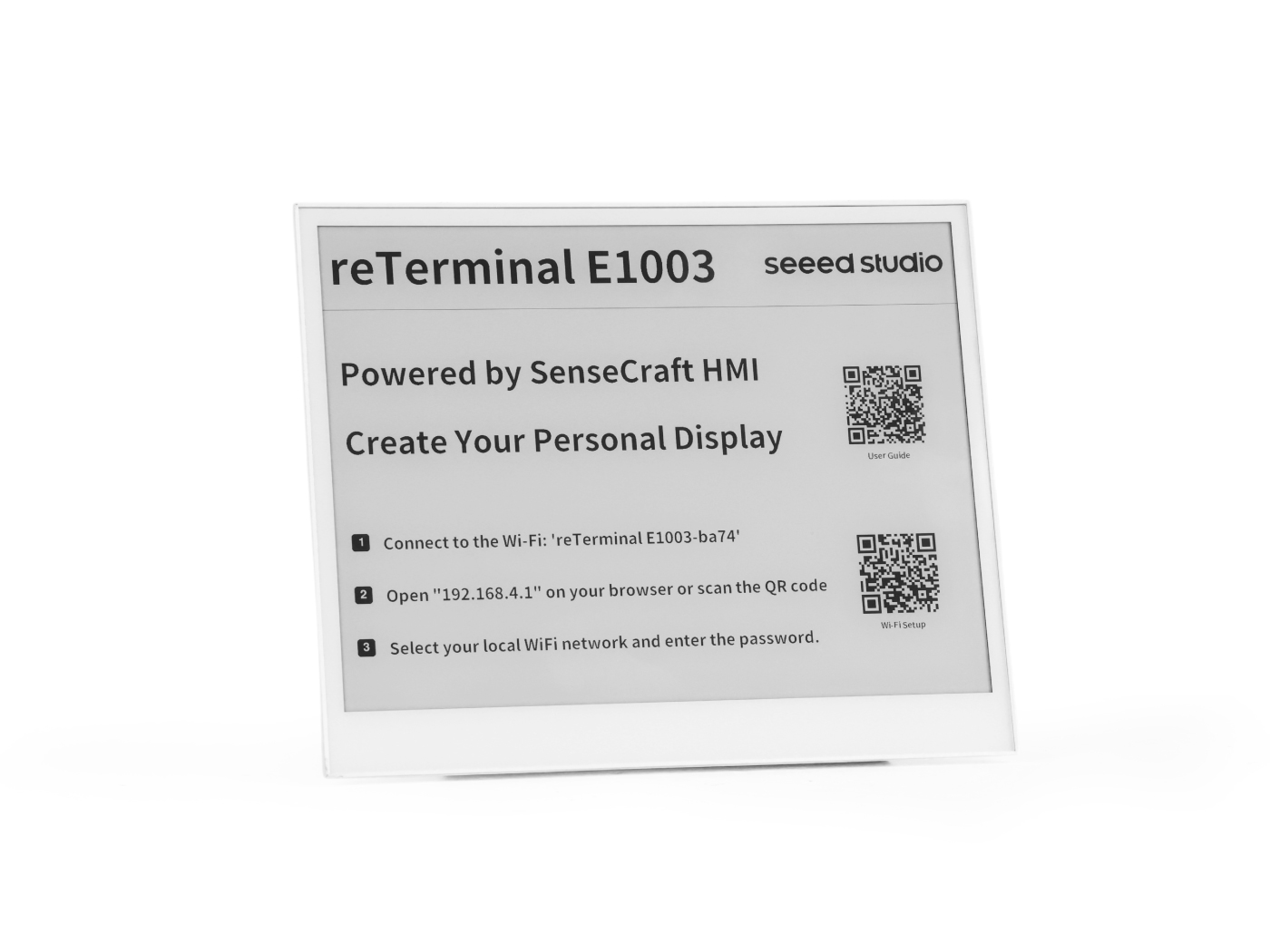
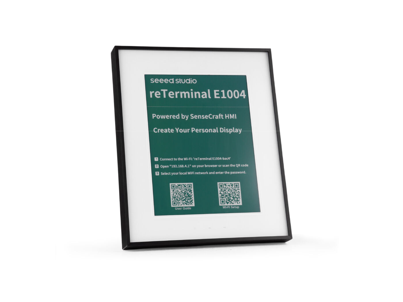
Este cookbook se aplica a la reTerminal E Serie. Elige el dispositivo que tengas a mano:
| reTerminal E1001 | reTerminal E1002 | reTerminal E1003 | reTerminal E1004 |
|---|---|---|---|
 |  |  |  |
Requisitos previos
Antes de ejecutar cualquiera de los ejemplos siguientes, ya deberías tener:
- El Arduino IDE instalado con el paquete de placas ESP32 (≥ 3.0 para el micrófono PDM) y la placa XIAO_ESP32S3 seleccionada.
- PSRAM configurada como OPI PSRAM y Flash configurada como 8 MB en el menú Tools.
- Un cable de datos USB-C funcional y el puerto serie correcto seleccionado.
- Verificado que puedes flashear un sketch básico al dispositivo; consulta la preparación del entorno en Arduino Cookbook: ePaper Display si aún no lo has hecho.
Todos los sketches de este cookbook imprimen información de depuración a través de Serial1 en los pines GPIO44 (RX) / GPIO43 (TX) a 115200 baudios; este es el puente USB-UART portador, no el USB-CDC Serial que el Arduino IDE abre automáticamente. Abre el Monitor Serie de Arduino y selecciona el puerto y la velocidad en baudios correspondientes para seguir la salida.
Resumen de compatibilidad de hardware
No todas las funciones de este cookbook están disponibles en los cuatro modelos. La tabla siguiente resume lo que puedes usar:
| Función | E1001 | E1002 | E1003 | E1004 |
|---|---|---|---|---|
| PCF8563 RTC (externo, I2C 0x51, respaldo CR1220) | ✅ | ✅ | ✅ | ✅ |
| Deep sleep / light sleep | ✅ | ✅ | ✅ | ✅ |
| Activación por botón (KEY0) | ✅ | ✅ | ✅ | ✅ |
| Grabación con micrófono PDM | ✅ | ✅ | ✅ | ❌ |
| Panel táctil capacitivo | ❌ | ❌ | ✅ | ❌ |
Reloj en tiempo real (RTC)
Cada modelo de la reTerminal E Serie incluye un chip de reloj en tiempo real PCF8563 de NXP integrado, con su propio cristal de 32,768 kHz y un portapilas para batería tipo moneda CR1220 que mantiene el tiempo en marcha incluso cuando se retira o se agota por completo la batería principal.
La pila tipo moneda CR1220 no se envía con el dispositivo. Debes comprar una batería CR1220 por separado e instalarla antes de que el RTC pueda conservar la hora entre ciclos de alimentación.
Instalación de la batería CR1220
El portapilas CR1220 se encuentra en la parte posterior de la PCB. Los pasos de desmontaje difieren ligeramente entre modelos:
- E1001 / E1002
- E1003
- E1004
Paso 1 — Apaga el dispositivo
Desconecta el cable USB-C y asegúrate de que el dispositivo esté completamente apagado.
Paso 2 — Retira la tapa trasera
Retira los cuatro tornillos del panel posterior y levanta la tapa trasera para dejar al descubierto la PCB.
Paso 3 — Localiza el portapilas
Localiza el portapilas tipo moneda CR1220 en la PCB (marcado como BT2 o CR1220).
Paso 4 — Inserta la batería
Coloca la batería CR1220 en el portapilas con el lado positivo (+) hacia arriba. Presiona suavemente hasta que encaje en su sitio.
Paso 5 — Vuelve a montar
Vuelva a colocar la tapa trasera y apriete los cuatro tornillos. El RTC ahora tiene respaldo de batería y mantendrá la hora incluso cuando se desconecte la alimentación principal.
Paso 1 — Apagar el dispositivo
Desconecta el cable USB-C y asegúrate de que el dispositivo esté completamente apagado.
Paso 2 — Retirar la tapa trasera
Retira los tornillos del panel trasero y levanta la tapa posterior para dejar al descubierto la PCB.
Paso 3 — Localizar el portapilas
Encuentra el portapilas tipo moneda CR1220 en la PCB (marcado como BT2 o CR1220).
Paso 4 — Insertar la batería
Coloca la batería CR1220 en el portapilas con el lado positivo (+) hacia arriba. Presiona suavemente hasta que encaje en su lugar.
Paso 5 — Volver a montar
Vuelve a colocar la tapa trasera y aprieta los tornillos. El RTC ahora tiene respaldo de batería y mantendrá la hora incluso cuando se desconecte la alimentación principal.
Paso 1 — Apagar el dispositivo
Desconecta el cable USB-C y asegúrate de que el dispositivo esté completamente apagado.
Paso 2 — Retirar la tapa trasera
Retira los tornillos alrededor del perímetro del panel trasero y levanta con cuidado la tapa posterior para dejar al descubierto la PCB.
Paso 3 — Localizar el portapilas
Encuentra el portapilas tipo moneda CR1220 en la PCB (marcado como BT2 o CR1220).
Paso 4 — Insertar la batería
Coloca la batería CR1220 en el portapilas con el lado positivo (+) hacia arriba. Presiona suavemente hasta que encaje en su lugar.
Paso 5 — Volver a montar
Vuelve a colocar la tapa trasera y aprieta todos los tornillos. El RTC ahora tiene respaldo de batería y mantendrá la hora incluso cuando se desconecte la alimentación principal.
Descripción general del hardware
| Parámetro | Valor |
|---|---|
| Chip | PCF8563M/TR (NXP) |
| Bus | I2C — dirección 0x51 (fijada en silicio) |
| SCL | GPIO20 |
| SDA | GPIO19 |
| Cristal | 32,768 kHz (pines OSCI / OSCO) |
| Batería de respaldo | Pila tipo moneda CR1220 — mantiene la hora cuando se retira la alimentación principal |
| Bandera VL | Establecida por el chip cuando el voltaje de la batería de respaldo es demasiado bajo; indica que la hora no es fiable |
Sketch completo: RTC_PCF8563
El sketch completo está disponible en el repositorio: examples/RTC_PCF8563/RTC_PCF8563.ino.
Haz clic para desplegar el código completo de RTC_PCF8563.ino
// ============================================================
// USER CONFIGURATION
// ============================================================

// --- How to set the initial time ---
//
// OPTION A — Compile-time (recommended):
//   Uncomment USE_COMPILE_TIME.  The C compiler embeds __DATE__ / __TIME__
//   (the exact moment you clicked "Upload") into the binary automatically.
//   No need to type the date by hand — just compile and flash.
//
#define USE_COMPILE_TIME
//
// OPTION B — Manual:
//   Comment out USE_COMPILE_TIME above, then fill in the values below.
//   INITIAL_YEAR must be in the range 2000–2099.
#define INITIAL_YEAR   2026
#define INITIAL_MONTH     5   // 1–12
#define INITIAL_DAY      26   // 1–31
#define INITIAL_HOUR     14   // 0–23
#define INITIAL_MIN       0   // 0–59
#define INITIAL_SEC       0   // 0–59

// --- When to write the time ---
//
// You do NOT need to touch anything here for normal use.
//
// How it works automatically:
//   • New board / battery just replaced → PCF8563 sets VL=1 internally
//     → code detects VL=1 at boot → writes the initial time once → done.
//   • Every reboot after that (battery healthy, VL=0)
//     → stored time is kept, nothing is overwritten.
//
// FORCE_SET_TIME is only for manual re-calibration (e.g. correcting drift).
// If you uncomment it, the clock is overwritten on EVERY boot — make sure
// to comment it out again and re-flash right after calibrating.
//
// #define FORCE_SET_TIME

// ============================================================
// END OF USER CONFIGURATION — no need to edit below this line
// ============================================================

#include <Wire.h>
#include <time.h>
#include <sys/time.h>

// ============================================================
// RtcTime — carries all date/time fields returned by rtcGetTime().
//
// Defined here, right after the #includes, so that Arduino IDE's
// automatic function-prototype injection (which is inserted after
// the last #include) can see the type before using it in prototypes
// like  static bool rtcGetTime(RtcTime &rt).
// ============================================================
struct RtcTime {
    int  year;       // full year (e.g. 2026)
    int  month;      // 1–12
    int  day;        // 1–31
    int  weekday;    // 0=Sunday … 6=Saturday
    int  hour;       // 0–23
    int  minute;     // 0–59
    int  second;     // 0–59
    bool voltageOK;  // false → VL flag set, battery was drained, time unreliable
};

// ---------- Serial debug (carrier USB-UART bridge) ----------
#define PIN_SERIAL_RX   44
#define PIN_SERIAL_TX   43
#define LOG             Serial1

// ---------- I2C pins (identical on all E1001 / E1002 / E1003 / E1004) --------
#define PIN_I2C_SCL     20   // ESP_IO20 / I2C0_SCL
#define PIN_I2C_SDA     19   // ESP_IO19 / I2C0_SDA

// ---------- PCF8563 I2C address (7-bit, fixed in hardware) -------------------
#define PCF8563_ADDR    0x51

// ---------- PCF8563 register map (only the registers used here) --------------
#define REG_CTRL1       0x00   // Control/Status 1 — bit5 STOP halts the clock
#define REG_CTRL2       0x01   // Control/Status 2
#define REG_SECONDS     0x02   // bit7 = VL (voltage-low flag); bits6:0 = seconds
#define REG_MINUTES     0x03   // bits6:0 = minutes
#define REG_HOURS       0x04   // bits5:0 = hours
#define REG_DAYS        0x05   // bits5:0 = day-of-month
#define REG_WEEKDAYS    0x06   // bits2:0 = weekday (0=Sunday)
#define REG_MONTHS      0x07   // bit7 = century (0→2000s, 1→1900s); bits4:0 = month
#define REG_YEARS       0x08   // bits7:0 = year within century (BCD, 00–99)
#define REG_CLKOUT      0x0D   // CLKOUT control — bit7 FE enables clock output pin

// ============================================================
// BCD ↔ decimal conversion
// The PCF8563 stores all time fields in BCD (Binary-Coded Decimal):
//   e.g. decimal 26 → upper nibble=2, lower nibble=6 → 0x26
// ============================================================
static inline uint8_t bcdToDec(uint8_t bcd)
{
    return static_cast<uint8_t>(((bcd >> 4) * 10U) + (bcd & 0x0FU));
}

static inline uint8_t decToBcd(uint8_t dec)
{
    return static_cast<uint8_t>(((dec / 10U) << 4) | (dec % 10U));
}

// ============================================================
// I2C read / write helpers
// ============================================================

// Read `len` consecutive registers starting at `reg` into `buf`.
// Uses a repeated-START (no STOP between write and read) as required by the
// PCF8563 data sheet.
static bool rtcReadRegs(uint8_t reg, uint8_t *buf, size_t len)
{
    Wire.beginTransmission(PCF8563_ADDR);
    Wire.write(reg);
    if (Wire.endTransmission(false) != 0) return false;   // repeated START

    const uint8_t received = Wire.requestFrom(static_cast<uint8_t>(PCF8563_ADDR),
                                              static_cast<uint8_t>(len));
    if (received != len) return false;

    for (size_t i = 0; i < len; i++) {
        buf[i] = static_cast<uint8_t>(Wire.read());
    }
    return true;
}

// Write a single register.
static bool rtcWriteReg(uint8_t reg, uint8_t value)
{
    Wire.beginTransmission(PCF8563_ADDR);
    Wire.write(reg);
    Wire.write(value);
    return Wire.endTransmission() == 0;
}

// ============================================================
// PCF8563 API
// ============================================================

// Check whether the chip responds on the I2C bus.
static bool rtcProbe()
{
    Wire.beginTransmission(PCF8563_ADDR);
    return Wire.endTransmission() == 0;
}

// Clear the STOP bit so the oscillator runs, and disable the CLKOUT pin
// (saves a small amount of power when the clock output is not needed).
static bool rtcInit()
{
    if (!rtcWriteReg(REG_CTRL1, 0x00)) return false;   // STOP=0 → run
    if (!rtcWriteReg(REG_CTRL2, 0x00)) return false;   // clear alarm/timer flags
    if (!rtcWriteReg(REG_CLKOUT, 0x00)) return false;  // FE=0 → disable CLKOUT
    return true;
}

// Return false if the voltage-low flag is set (time data is unreliable).
static bool rtcVoltageOK()
{
    uint8_t sec = 0;
    if (!rtcReadRegs(REG_SECONDS, &sec, 1)) return false;
    return (sec & 0x80U) == 0U;   // VL bit = 0 means voltage has been OK
}

// Write date and time to the RTC.
// `year` must be in the range 2000–2099.
// Weekday is computed automatically from the supplied date.
static bool rtcSetTime(int year, int month, int day,
                       int hour, int minute, int second)
{
    if (year  < 2000 || year  > 2099) return false;
    if (month < 1    || month > 12  ) return false;
    if (day   < 1    || day   > 31  ) return false;
    if (hour  < 0    || hour  > 23  ) return false;
    if (minute < 0   || minute > 59 ) return false;
    if (second < 0   || second > 59 ) return false;

    // Use mktime() to derive the weekday (0=Sunday) from the calendar date.
    struct tm t = {};
    t.tm_year = year - 1900;
    t.tm_mon  = month - 1;
    t.tm_mday = day;
    mktime(&t);   // fills t.tm_wday

    // Write all 7 time registers in one burst starting at REG_SECONDS.
    // The PCF8563 auto-increments the internal address pointer after each byte.
    Wire.beginTransmission(PCF8563_ADDR);
    Wire.write(REG_SECONDS);
    Wire.write(decToBcd(static_cast<uint8_t>(second)));
    Wire.write(decToBcd(static_cast<uint8_t>(minute)));
    Wire.write(decToBcd(static_cast<uint8_t>(hour)));
    Wire.write(decToBcd(static_cast<uint8_t>(day)));
    Wire.write(static_cast<uint8_t>(t.tm_wday));         // weekday is not BCD
    Wire.write(decToBcd(static_cast<uint8_t>(month)));   // century bit = 0 → 2000s
    Wire.write(decToBcd(static_cast<uint8_t>(year % 100)));
    return Wire.endTransmission() == 0;
}

// Read the current date and time from the RTC into an RtcTime struct.
static bool rtcGetTime(RtcTime &rt)
{
    uint8_t raw[7] = {};
    // Burst-read 7 bytes: seconds, minutes, hours, days, weekdays, months, years
    if (!rtcReadRegs(REG_SECONDS, raw, 7)) return false;

    rt.voltageOK = (raw[0] & 0x80U) == 0U;                // VL flag
    rt.second    = bcdToDec(raw[0] & 0x7FU);
    rt.minute    = bcdToDec(raw[1] & 0x7FU);
    rt.hour      = bcdToDec(raw[2] & 0x3FU);
    rt.day       = bcdToDec(raw[3] & 0x3FU);
    rt.weekday   = bcdToDec(raw[4] & 0x07U);
    rt.month     = bcdToDec(raw[5] & 0x1FU);

    const int yr = bcdToDec(raw[6]);
    // Century bit 1 in REG_MONTHS → 1900s, bit 0 → 2000s
    rt.year      = ((raw[5] & 0x80U) != 0U) ? (1900 + yr) : (2000 + yr);

    return true;
}

// ============================================================
// Sync the ESP32's POSIX system clock from the RTC.
// After calling this, standard C functions like time(), localtime(),
// and strftime() will return the correct time.
// ============================================================
static void syncSystemClock(const RtcTime &rt)
{
    struct tm t = {};
    t.tm_year = rt.year - 1900;
    t.tm_mon  = rt.month - 1;
    t.tm_mday = rt.day;
    t.tm_hour = rt.hour;
    t.tm_min  = rt.minute;
    t.tm_sec  = rt.second;
    const time_t epoch = mktime(&t);
    struct timeval tv  = { epoch, 0 };
    settimeofday(&tv, nullptr);
}

// ============================================================
// Compile-time timestamp parser
//
// The C preprocessor provides two string literals in every translation unit:
//   __DATE__  →  "May 26 2026"  (month name, day, 4-digit year)
//   __TIME__  →  "14:53:00"    (HH:MM:SS, 24-hour)
//
// We parse them here so callers get plain integers without any library.
// ============================================================
#ifdef USE_COMPILE_TIME
static void getCompileTime(int &year, int &month, int &day,
                           int &hour, int &minute, int &second)
{
    // Map the 3-letter month abbreviation to 1–12.
    // strncmp compares only the first 3 characters, so this is safe.
    const char *abbr  = __DATE__;       // "May 26 2026"
    const char *names = "JanFebMarAprMayJunJulAugSepOctNovDec";
    month = 1;
    for (int i = 0; i < 12; i++) {
        if (strncmp(abbr, names + i * 3, 3) == 0) { month = i + 1; break; }
    }

    // __DATE__ + 4  →  "26 2026"  (day starts at offset 4)
    // __DATE__ + 7  →  "2026"     (year starts at offset 7)
    day  = atoi(__DATE__ + 4);
    year = atoi(__DATE__ + 7);

    // __TIME__      →  "14:53:00"
    // __TIME__ + 3  →  "53:00"
    // __TIME__ + 6  →  "00"
    hour   = atoi(__TIME__);
    minute = atoi(__TIME__ + 3);
    second = atoi(__TIME__ + 6);
}
#endif  // USE_COMPILE_TIME

// ============================================================
// Helpers
// ============================================================
static const char *kWeekdayNames[] = {
    "Sun", "Mon", "Tue", "Wed", "Thu", "Fri", "Sat"
};

// ============================================================
// Global state
// ============================================================
static unsigned long s_lastPrintMs = 0;

// ============================================================
// setup()
// ============================================================
void setup()
{
    // Use Serial1 (the USB-UART bridge on the carrier board, not USB-CDC).
    // GPIO43 = TX, GPIO44 = RX of the bridge chip.
    LOG.begin(115200, SERIAL_8N1, PIN_SERIAL_RX, PIN_SERIAL_TX);
    delay(500);

    LOG.println("=========================================");
    LOG.println("  RTC_PCF8563 — reTerminal E Series");
    LOG.println("=========================================");

    // ── Step 1: initialise I2C at 400 kHz (PCF8563 supports up to 400 kHz) ──
    Wire.begin(PIN_I2C_SDA, PIN_I2C_SCL);
    Wire.setClock(400000UL);
    LOG.printf("[I2C] Bus started: SDA=GPIO%d  SCL=GPIO%d  400 kHz\n",
               PIN_I2C_SDA, PIN_I2C_SCL);

    // ── Step 2: check the PCF8563 is reachable ──
    LOG.printf("[RTC] Probing PCF8563 at I2C address 0x%02X ...", PCF8563_ADDR);
    if (!rtcProbe()) {
        LOG.println(" NOT FOUND");
        LOG.println("[RTC] FATAL: check wiring and backup battery. Halting.");
        while (true) delay(1000);
    }
    LOG.println(" OK");

    // ── Step 3: clear STOP bit, disable CLKOUT ──
    if (!rtcInit()) {
        LOG.println("[RTC] FATAL: could not initialise PCF8563. Halting.");
        while (true) delay(1000);
    }

    // ── Step 4: decide whether the time needs to be set ──
    //
    // The VL (voltage-low) flag is stored inside the PCF8563 and survives
    // power cycles.  It is set by the chip whenever the backup battery
    // voltage has been too low to keep the clock running reliably.
    // We treat a set VL flag as "time is unknown and must be initialised".
    const bool voltageWasLow = !rtcVoltageOK();

#ifdef FORCE_SET_TIME
    const bool doSetTime = true;
    LOG.println("[RTC] FORCE_SET_TIME defined — overwriting RTC time.");
#else
    const bool doSetTime = voltageWasLow;
    if (voltageWasLow) {
        LOG.println("[RTC] WARNING: VL flag set — backup battery may be depleted.");
        LOG.println("[RTC] Time is unreliable; resetting to INITIAL_* constants.");
    } else {
        LOG.println("[RTC] Battery OK — retaining stored time.");
    }
#endif

    if (doSetTime) {
#ifdef USE_COMPILE_TIME
        // Parse the timestamp baked in at compile time.
        // __DATE__ / __TIME__ are evaluated by the C preprocessor during
        // compilation, so they reflect the moment "Upload" was clicked.
        int cy, cm, cd, ch, cmin, cs;
        getCompileTime(cy, cm, cd, ch, cmin, cs);
        LOG.printf("[RTC] Setting time from compile timestamp: "
                   "%04d-%02d-%02d  %02d:%02d:%02d\n",
                   cy, cm, cd, ch, cmin, cs);
        if (!rtcSetTime(cy, cm, cd, ch, cmin, cs)) {
            LOG.println("[RTC] ERROR: rtcSetTime() failed.");
        }
#else
        LOG.printf("[RTC] Setting time from INITIAL_* constants: "
                   "%04d-%02d-%02d  %02d:%02d:%02d\n",
                   INITIAL_YEAR, INITIAL_MONTH, INITIAL_DAY,
                   INITIAL_HOUR, INITIAL_MIN,   INITIAL_SEC);
        if (!rtcSetTime(INITIAL_YEAR, INITIAL_MONTH, INITIAL_DAY,
                        INITIAL_HOUR, INITIAL_MIN,   INITIAL_SEC)) {
            LOG.println("[RTC] ERROR: rtcSetTime() failed.");
        }
#endif
    }

    // ── Step 5: read back and sync the ESP32 system clock ──
    //
    // The ESP32 has its own software RTC that resets to Jan 1 1970 on each
    // power cycle.  By calling settimeofday() once at boot, we keep the
    // ESP32's POSIX time() / localtime() / strftime() in sync with the
    // hardware RTC so the rest of the firmware can use standard C time APIs.
    RtcTime rt;
    if (rtcGetTime(rt)) {
        syncSystemClock(rt);
        LOG.printf("[RTC] Current time: %04d-%02d-%02d (%s)  %02d:%02d:%02d\n",
                   rt.year, rt.month, rt.day, kWeekdayNames[rt.weekday],
                   rt.hour, rt.minute, rt.second);
        LOG.println("[RTC] ESP32 system clock synced.");
    } else {
        LOG.println("[RTC] ERROR: could not read time after init.");
    }

    LOG.println();
    LOG.println("[READY] Printing time every second.");
}

// ============================================================
// loop()
// ============================================================
void loop()
{
    const unsigned long now = millis();

    // Print time once per second (non-blocking: compare elapsed time instead
    // of calling delay(), so other tasks in loop() are never blocked).
    if (now - s_lastPrintMs >= 1000UL) {
        s_lastPrintMs = now;

        RtcTime rt;
        if (rtcGetTime(rt)) {
            // Show the time read directly from the hardware RTC.
            // The "[VL]" tag warns that the chip saw a low-voltage event.
            LOG.printf("[TIME] %04d-%02d-%02d (%s)  %02d:%02d:%02d%s\n",
                       rt.year, rt.month, rt.day,
                       kWeekdayNames[rt.weekday],
                       rt.hour, rt.minute, rt.second,
                       rt.voltageOK ? "" : "  [VL: battery low!]");

            // ── Optional: also print the time via the ESP32 POSIX API ──
            // This demonstrates that the system clock (synced at boot) is
            // ticking independently of the I2C bus.
            char buf[32];
            time_t epoch = time(nullptr);
            struct tm info;
            localtime_r(&epoch, &info);
            strftime(buf, sizeof(buf), "%Y-%m-%d %H:%M:%S", &info);
            LOG.printf("[SYS ] ESP32 system time: %s\n", buf);

        } else {
            LOG.println("[RTC] ERROR: rtcGetTime() failed — check I2C bus.");
        }
    }
}
Cómo funciona el código
El código sigue una secuencia de inicialización de 5 pasos en setup():
- Inicializar el bus I2C a 400 kHz en GPIO19 (SDA) / GPIO20 (SCL), los pines I2C estándar de reTerminal compartidos con el sensor SHT4x.
- Sondear el PCF8563 en la dirección 0x51 para verificar que el chip está respondiendo.
- Inicializar el chip: borrar el bit STOP (para que el oscilador funcione), borrar las banderas de alarma y deshabilitar el pin CLKOUT para ahorrar energía.
- Decidir si se debe ajustar la hora: el PCF8563 tiene una bandera VL (Voltage Low) que se establece automáticamente cuando el voltaje de la batería de respaldo cae demasiado. Si VL está activada (primer arranque o batería reemplazada), el código escribe la hora inicial; de lo contrario mantiene la hora almacenada.
- Sincronizar el reloj del sistema del ESP32: después de leer la hora del PCF8563, se llama a
settimeofday()para que las funciones de tiempo estándar de C (time(),localtime(),strftime()) devuelvan la hora correcta en el resto del firmware.
El loop() lee el RTC una vez por segundo vía I2C e imprime la hora formateada. La etiqueta [VL] aparece si el voltaje de la batería de respaldo es bajo.
Opciones para ajustar la hora
| Opción | Cómo activarla | Comportamiento |
|---|---|---|
| En tiempo de compilación (recomendado) | #define USE_COMPILE_TIME | El preprocesador de C inserta __DATE__ / __TIME__ (el momento en que hiciste clic en Upload). Cero esfuerzo: solo compila y flashea. |
| Manual | Comenta USE_COMPILE_TIME, rellena las constantes INITIAL_* | Escribes la fecha y hora exactas. Útil para entornos sin conexión. |
| Forzar sobrescritura | #define FORCE_SET_TIME | Sobrescribe el RTC en cada arranque. Úsalo para recalibrar, luego coméntalo y vuelve a flashear. |
La bandera VL persiste entre ciclos de alimentación. Una vez que se ajusta la hora y la batería CR1220 está en buen estado, el PCF8563 sigue funcionando y los reinicios posteriores no la sobrescriben.
Salida esperada
=========================================
  RTC_PCF8563 — reTerminal E Series
=========================================
[RTC] 2026-05-27 (Wed) 14:53:00
[READY] Printing time every second.
[TIME] 2026-05-27 (Wed) 14:53:01
[TIME] 2026-05-27 (Wed) 14:53:02
[TIME] 2026-05-27 (Wed) 14:53:03
Si la batería de respaldo está agotada o ausente, verás la advertencia [VL: battery low!]:
[RTC] WARNING: VL flag set — backup battery may be depleted.
[TIME] 2026-05-27 (Wed) 14:53:01  [VL: battery low!]
Modos de bajo consumo
El ESP32-S3 admite varios estados de energía. Los dos más útiles para aplicaciones de ePaper alimentadas por batería son deep sleep y light sleep:
| Estado de energía | CPU | Wi-Fi / BT | RAM | RTC | Fuente de activación |
|---|---|---|---|---|---|
| Activo | En ejecución | Encendido | Toda | Encendido | — |
| Light Sleep | Pausada | Apagado | Retenida | Encendido | GPIO, Temporizador |
| Deep Sleep | Apagado | Apagado | Perdida (excepto RTC) | Encendido | GPIO, Temporizador, Táctil |
Sketch completo: LowPower_DeepSleep
El sketch completo está disponible en el repositorio: examples/LowPower_DeepSleep/LowPower_DeepSleep.ino.
Haz clic para expandir todo el código de LowPower_DeepSleep.ino
// ============================================================
// USER CONFIGURATION
// ============================================================

// How many seconds to stay awake before entering deep sleep.
#define SLEEP_DELAY_SEC   5

// --- Wake-up button pin ---
// Uncomment the ONE line that matches your device.
// Only GPIO0–GPIO21 can wake the ESP32-S3 from deep sleep.
//
#define PIN_WAKE_BTN   3   // E1001 / E1002 / E1003 — KEY0
// #define PIN_WAKE_BTN   4   // E1004               — KEY0

// ============================================================
// END OF USER CONFIGURATION
// ============================================================

#include "esp_sleep.h"
#include "driver/rtc_io.h"

#define PIN_SERIAL_RX   44
#define PIN_SERIAL_TX   43
#define LOG             Serial1

// Survives deep sleep — increments on every wakeup.
RTC_DATA_ATTR static int s_bootCount = 0;

static const char* wakeupReason()
{
    switch (esp_sleep_get_wakeup_cause()) {
        case ESP_SLEEP_WAKEUP_EXT1:  return "GPIO button (EXT1)";
        default:                     return "power-on / manual reset";
    }
}

void setup()
{
    s_bootCount++;

    LOG.begin(115200, SERIAL_8N1, PIN_SERIAL_RX, PIN_SERIAL_TX);
    delay(100);

    LOG.println("========================================");
    LOG.println("  LowPower_DeepSleep — reTerminal E");
    LOG.println("========================================");
    LOG.printf("[WAKE] Boot #%d — wakeup: %s\n", s_bootCount, wakeupReason());
    LOG.printf("[WAKE] Entering deep sleep in %d seconds...\n", SLEEP_DELAY_SEC);
    LOG.printf("[WAKE] Press GPIO%d button to wake up.\n", PIN_WAKE_BTN);

    delay((uint32_t)SLEEP_DELAY_SEC * 1000);

    esp_sleep_enable_ext1_wakeup(1ULL << PIN_WAKE_BTN, ESP_EXT1_WAKEUP_ANY_LOW);

    // Normal GPIO pull-up is off during deep sleep; use keep-alive domain instead.
    rtc_gpio_pullup_en(static_cast<gpio_num_t>(PIN_WAKE_BTN));
    rtc_gpio_pulldown_dis(static_cast<gpio_num_t>(PIN_WAKE_BTN));

    LOG.println("[SLEEP] Entering deep sleep now.");
    LOG.flush();
    delay(10);

    esp_deep_sleep_start();
}

void loop()
{
    // esp_deep_sleep_start() in setup() never returns, so loop() is never reached.
    // If you see this message, deep sleep failed to start.
    LOG.println("[ERROR] deep sleep did not start!");
    delay(1000);
}
Cómo funciona el código
- Comienza
setup(): incrementa el contador de arranquesRTC_DATA_ATTR(esta variable se mantiene en el dominio de memoria RTC del ESP32-S3, por lo que sobrevive al deep sleep). - Imprime el estado: muestra el número de arranques y por qué se despertó el chip (botón GPIO frente a reinicio por encendido).
- Espera
SLEEP_DELAY_SECsegundos (5 por defecto): esto te da tiempo para leer la salida serie. - Configura la fuente de activación:
esp_sleep_enable_ext1_wakeup()registra el pin del botón (KEY0). El nivel de activación esLOWporque los botones son activos en bajo con resistencias pull-up por hardware. - Habilita el pull-up del RTC: los pull-up GPIO normales se deshabilitan durante el deep sleep.
rtc_gpio_pullup_en()usa el pull-up del dominio RTC para mantener la línea del botón en HIGH mientras está dormido. - Entra en deep sleep:
esp_deep_sleep_start()apaga todo excepto el dominio RTC. La corriente cae a ~14 µA. - Al pulsar el botón: el dominio RTC detecta el flanco descendente del GPIO, el chip se reinicia y
setup()se ejecuta de nuevo desde el paso 1.
loop() contiene una instrucción de impresión que nunca debería ejecutarse. Si ves [ERROR] deep sleep did not start! en el monitor serie, el deep sleep falló. Silencio después de [SLEEP] significa que el dispositivo está realmente dormido.
Selección del pin de activación por botón
El botón de activación difiere entre modelos debido a la distribución de los GPIO:
| Modelo | Pin de activación | PIN_WAKE_BTN | Notas |
|---|---|---|---|
| E1001 / E1002 / E1003 | GPIO3 (KEY0) | 3 | Botón derecho (Botón Verde en E1001/E1002) |
| E1004 | GPIO4 (KEY0) | 4 | Botón de dirección derecho (panel frontal) |
Descomenta la línea correcta en la sección USER CONFIGURATION antes de flashear.
Salida esperada
Primer arranque (encendido):
========================================
  LowPower_DeepSleep — reTerminal E
========================================
[WAKE] Boot #1 — wakeup: power-on / manual reset
[WAKE] Entering deep sleep in 5 seconds...
[WAKE] Press GPIO3 button to wake up.
[SLEEP] Entering deep sleep now.
Después de pulsar KEY0 para despertar:
========================================
  LowPower_DeepSleep — reTerminal E
========================================
[WAKE] Boot #2 — wakeup: GPIO button (EXT1)
[WAKE] Entering deep sleep in 5 seconds...
[WAKE] Press GPIO3 button to wake up.
[SLEEP] Entering deep sleep now.
Patrón Despertar → Trabajar → Dormir
Un patrón común para aplicaciones de ePaper es:
- Despertar desde deep sleep (temporizador o botón).
- Leer el RTC para poner marcas de tiempo.
- Leer sensores (SHT4x, batería, etc.).
- Conectarse a Wi-Fi y obtener datos, si es necesario.
- Actualizar la pantalla de ePaper con la nueva información.
- Volver a deep sleep hasta el siguiente despertar programado.
Para añadir un despertar por temporizador además del despertar por botón, simplemente añade:
esp_sleep_enable_timer_wakeup(30 * 60 * 1000000ULL); // 30 minutes
antes de llamar a esp_deep_sleep_start(). Ambas fuentes de activación pueden estar activas simultáneamente: la primera que se dispare gana.
Micrófono (E1001 / E1002 / E1003)
El reTerminal E1004 no incluye un micrófono integrado. Los ejemplos de esta sección se aplican solo a E1001, E1002 y E1003. Si estás usando un E1004, omite esta sección.
Los reTerminal E1001 / E1002 / E1003 incluyen un micrófono digital integrado PDM (Pulse Density Modulation). Los micrófonos PDM generan un flujo sigma-delta de 1 bit que es decodificado por el periférico PDM integrado del ESP32-S3; no se necesita ningún chip códec externo.
Descripción general del hardware
| Señal | Pin GPIO | Descripción |
|---|---|---|
| PDM_CLK | GPIO42 | Salida de reloj hacia el micrófono |
| PDM_DATA | GPIO41 | Entrada de datos de 1 bit desde el micrófono |
| MIC_PWR_EN | GPIO38 | Habilitación de alimentación del micrófono (activo en HIGH): debe ponerse en HIGH antes de usar |
Los pines son los mismos en E1001, E1002 y E1003. El pin de habilitación de alimentación del micrófono (GPIO38) controla un interruptor de carga (TPS22916CYFPR); debes ponerlo en HIGH antes de grabar y puedes ponerlo en LOW después para ahorrar energía.
El sketch utiliza la API ESP-IDF 5.x PDM-RX (driver/i2s_pdm.h), que solo está disponible en la versión 3.0 o superior del core Arduino ESP32. Asegúrate de que el paquete de tu placa esté actualizado.
Sketch completo: MicRecordToSD
El sketch completo está disponible en el repositorio: examples/MicRecordToSD/MicRecordToSD.ino.
Haz clic para expandir el código completo de MicRecordToSD.ino
// ============================================================
// USER CONFIGURATION
// ============================================================

// Uncomment ONE line to select your hardware model:
// #define DEVICE_E1001_E1002   // reTerminal E1001 or E1002
#define DEVICE_E1003      // reTerminal E1003

// Recording parameters
#define SAMPLE_RATE      16000U  // Sample rate in Hz (8000 / 16000 / 44100)
#define MAX_RECORD_SECS  30      // Auto-stop after this many seconds (0 = unlimited)
#define RECORD_DIR       "/REC"  // Directory on the SD card root

// ============================================================
// END OF USER CONFIGURATION — no need to edit below this line
// ============================================================

#include <SD.h>
#include <SPI.h>
#include <driver/i2s_pdm.h>    // ESP-IDF 5.x PDM-RX API (Arduino ESP32 >= 3.0)
#include <driver/i2s_common.h>

// ---------- Serial debug ---------
#define PIN_SERIAL_RX   44
#define PIN_SERIAL_TX   43
#define LOG             Serial1

// ---------- PDM Microphone -------
// Same on E1001, E1002, and E1003.
#define PIN_MIC_CLK     42   // GPIO42 — PDM_CLK  (R109 in schematic)
#define PIN_MIC_DATA    41   // GPIO41 — PDM_DATA (R110 in schematic)
#define PIN_MIC_PWR_EN  38   // GPIO38 — MIC power enable (TPS22916CYFPR EN, ESP_IO3B)

// ---------- SD Card --------------
// SPI bus is shared with the ePaper display; a separate CS keeps them independent.
#define PIN_SD_DET       15  // Card detect (LOW = card present)
#define PIN_SD_CS        14  // SPI Chip Select
#define PIN_SD_MISO       8
#define PIN_SD_MOSI       9
#define PIN_SD_SCK        7

// ---------- User Button ----------
#define PIN_BTN_KEY0      3  // KEY0 — active LOW (hardware pull-up)

// ---------- Model-specific pins --
#if defined(DEVICE_E1001_E1002)
  #define PIN_SD_EN    16    // GPIO16 — SD card power enable
  #define PIN_LED       6    // GPIO6  — onboard LED (inverted: LOW = ON)
#elif defined(DEVICE_E1003)
  #define PIN_SD_EN    39    // GPIO39 — SD card power enable
  #define PIN_LED      16    // GPIO16 — onboard LED (inverted: LOW = ON)
#else
  #error "Please define DEVICE_E1001_E1002 or DEVICE_E1003 in the USER CONFIGURATION section."
#endif

// ---------- I2S / Audio ----------
#define I2S_PORT          I2S_NUM_0
#define DMA_BUF_COUNT     8     // number of DMA descriptors
#define DMA_BUF_LEN       512   // frames per DMA descriptor
#define BITS_PER_SAMPLE   16
#define AUDIO_CHANNELS    1
#define BYTES_PER_SAMPLE  (BITS_PER_SAMPLE / 8)
#define BYTES_PER_SEC     (SAMPLE_RATE * AUDIO_CHANNELS * BYTES_PER_SAMPLE)

// Single-read chunk: matches one DMA buffer (512 frames × 2 bytes = 1024 bytes)
#define READ_BUF_BYTES    (DMA_BUF_LEN * BYTES_PER_SAMPLE)
static uint8_t s_dmaBuf[READ_BUF_BYTES];

// ============================================================
// WAV file header (44 bytes, little-endian)
// ============================================================
#pragma pack(push, 1)
struct WavHeader {
    // RIFF chunk
    char     riffTag[4];      // "RIFF"
    uint32_t riffSize;        // file size − 8
    char     waveTag[4];      // "WAVE"
    // fmt sub-chunk
    char     fmtTag[4];       // "fmt "
    uint32_t fmtSize;         // 16 for PCM
    uint16_t audioFormat;     // 1 = PCM
    uint16_t numChannels;     // 1 = mono
    uint32_t sampleRate;
    uint32_t byteRate;        // sampleRate × channels × bytesPerSample
    uint16_t blockAlign;      // channels × bytesPerSample
    uint16_t bitsPerSample;
    // data sub-chunk
    char     dataTag[4];      // "data"
    uint32_t dataSize;        // audio payload in bytes
};
#pragma pack(pop)

static_assert(sizeof(WavHeader) == 44, "WavHeader must be 44 bytes");

// ============================================================
// Global state
// ============================================================
static i2s_chan_handle_t s_rxHandle    = nullptr;  // ESP-IDF 5.x channel handle
static SPIClass          s_spiSD(HSPI);
static File        s_wavFile;
static bool        s_recording     = false;
static uint32_t    s_recordedBytes = 0;
static uint32_t    s_fileIndex     = 1;

// Button debounce
static bool          s_lastRawBtn    = HIGH;
static bool          s_stableBtn     = HIGH;
static unsigned long s_debounceMs    = 0;
static const unsigned long DEBOUNCE_DELAY = 50;

// LED blink
static unsigned long s_lastBlinkMs  = 0;
static bool          s_ledState     = false;

// ============================================================
// LED helpers (inverted logic)
// ============================================================
static void ledOn()  { digitalWrite(PIN_LED, LOW);  }
static void ledOff() { digitalWrite(PIN_LED, HIGH); }

// ============================================================
// WAV helpers
// ============================================================
static void writeWavHeader(File& f, uint32_t dataBytes)
{
    WavHeader h;
    memcpy(h.riffTag,  "RIFF", 4);
    h.riffSize     = 36 + dataBytes;
    memcpy(h.waveTag,  "WAVE", 4);
    memcpy(h.fmtTag,   "fmt ", 4);
    h.fmtSize      = 16;
    h.audioFormat  = 1;
    h.numChannels  = AUDIO_CHANNELS;
    h.sampleRate   = SAMPLE_RATE;
    h.byteRate     = BYTES_PER_SEC;
    h.blockAlign   = AUDIO_CHANNELS * BYTES_PER_SAMPLE;
    h.bitsPerSample = BITS_PER_SAMPLE;
    memcpy(h.dataTag,  "data", 4);
    h.dataSize     = dataBytes;
    f.write(reinterpret_cast<const uint8_t*>(&h), sizeof(h));
}

// ============================================================
// SD card helpers
// ============================================================
static bool mountSD()
{
    pinMode(PIN_SD_EN, OUTPUT);
    digitalWrite(PIN_SD_EN, HIGH);
    delay(10);

    s_spiSD.end();
    s_spiSD.begin(PIN_SD_SCK, PIN_SD_MISO, PIN_SD_MOSI, PIN_SD_CS);

    if (!SD.begin(PIN_SD_CS, s_spiSD)) {
        LOG.println("[SD] Initialization failed — check card and formatting (FAT32).");
        return false;
    }
    LOG.printf("[SD] Mounted. Type: %s  Size: %llu MB\n",
               SD.cardType() == CARD_SDHC ? "SDHC" : "SD",
               SD.cardSize() / (1024ULL * 1024ULL));
    return true;
}

static String nextFilename()
{
    if (!SD.exists(RECORD_DIR)) {
        SD.mkdir(RECORD_DIR);
    }
    char buf[32];
    while (true) {
        snprintf(buf, sizeof(buf), "%s/REC_%04u.WAV", RECORD_DIR, s_fileIndex);
        if (!SD.exists(buf)) break;
        s_fileIndex++;
        if (s_fileIndex > 9999) s_fileIndex = 1;
    }
    return String(buf);
}

// ============================================================
// PDM / I2S helpers  (ESP-IDF 5.x new-API, Arduino ESP32 >= 3.0)
// ============================================================
static bool initMic()
{
    // ── Step 1: power up the microphone via the load switch ──
    LOG.println("[MIC] Powering on microphone...");
    pinMode(PIN_MIC_PWR_EN, OUTPUT);
    digitalWrite(PIN_MIC_PWR_EN, HIGH);
    delay(50);  // give the LDO and PDM decimation filter time to start up

    // ── Step 2: create an I2S RX channel ──
    LOG.println("[MIC] Creating I2S channel...");
    i2s_chan_config_t chanCfg = I2S_CHANNEL_DEFAULT_CONFIG(I2S_NUM_0, I2S_ROLE_MASTER);
    chanCfg.dma_desc_num  = DMA_BUF_COUNT;
    chanCfg.dma_frame_num = DMA_BUF_LEN;
    chanCfg.auto_clear    = true;

    esp_err_t err = i2s_new_channel(&chanCfg, nullptr, &s_rxHandle);
    if (err != ESP_OK) {
        LOG.printf("[MIC] i2s_new_channel failed: 0x%x\n", err);
        return false;
    }

    // ── Step 3: configure PDM-RX mode ──
    LOG.println("[MIC] Configuring PDM-RX mode...");
    i2s_pdm_rx_config_t pdmCfg = {};
    pdmCfg.clk_cfg  = I2S_PDM_RX_CLK_DEFAULT_CONFIG(SAMPLE_RATE);
    pdmCfg.slot_cfg = I2S_PDM_RX_SLOT_DEFAULT_CONFIG(I2S_DATA_BIT_WIDTH_16BIT,
                                                      I2S_SLOT_MODE_MONO);
    pdmCfg.gpio_cfg.clk             = static_cast<gpio_num_t>(PIN_MIC_CLK);
    pdmCfg.gpio_cfg.din             = static_cast<gpio_num_t>(PIN_MIC_DATA);
    pdmCfg.gpio_cfg.invert_flags.clk_inv = false;

    err = i2s_channel_init_pdm_rx_mode(s_rxHandle, &pdmCfg);
    if (err != ESP_OK) {
        LOG.printf("[MIC] i2s_channel_init_pdm_rx_mode failed: 0x%x\n", err);
        i2s_del_channel(s_rxHandle);
        s_rxHandle = nullptr;
        return false;
    }

    // ── Step 4: enable (starts the clock and DMA) ──
    LOG.println("[MIC] Enabling channel...");
    err = i2s_channel_enable(s_rxHandle);
    if (err != ESP_OK) {
        LOG.printf("[MIC] i2s_channel_enable failed: 0x%x\n", err);
        i2s_del_channel(s_rxHandle);
        s_rxHandle = nullptr;
        return false;
    }

    // ── Step 5: warm-up — discard a few DMA buffers with a finite timeout ──
    // The PDM decimation filter needs several milliseconds to settle.
    // Using a 500 ms timeout instead of portMAX_DELAY prevents hanging if
    // the hardware is not producing data for any reason.
    LOG.println("[MIC] Warming up PDM filter...");
    size_t dummy;
    for (int i = 0; i < 3; i++) {
        i2s_channel_read(s_rxHandle, s_dmaBuf, sizeof(s_dmaBuf),
                         &dummy, pdMS_TO_TICKS(500));
    }

    LOG.printf("[MIC] PDM initialized. Rate=%u Hz  Bits=%d  CLK=GPIO%d  DATA=GPIO%d\n",
               SAMPLE_RATE, BITS_PER_SAMPLE, PIN_MIC_CLK, PIN_MIC_DATA);
    return true;
}

// ============================================================
// Recording control
// ============================================================
static bool startRecording()
{
    String fname = nextFilename();
    s_wavFile = SD.open(fname, FILE_WRITE);
    if (!s_wavFile) {
        LOG.printf("[REC] Cannot create file: %s\n", fname.c_str());
        return false;
    }
    writeWavHeader(s_wavFile, 0);   // placeholder — filled in when recording stops
    s_recordedBytes = 0;
    s_recording     = true;
    ledOn();
    LOG.printf("[REC] Recording started → %s\n", fname.c_str());
    return true;
}

static void stopRecording()
{
    s_recording = false;
    ledOff();

    // Seek back to the beginning and rewrite the header with the real data size.
    s_wavFile.seek(0);
    writeWavHeader(s_wavFile, s_recordedBytes);
    s_wavFile.close();

    float seconds = static_cast<float>(s_recordedBytes) / BYTES_PER_SEC;
    LOG.printf("[REC] Recording stopped. %u bytes saved (%.1f s).\n",
               s_recordedBytes, seconds);
    s_fileIndex++;
}

// ============================================================
// setup()
// ============================================================
void setup()
{
    LOG.begin(115200, SERIAL_8N1, PIN_SERIAL_RX, PIN_SERIAL_TX);
    delay(500);   // brief pause for the serial bridge to enumerate

    LOG.println("=========================================");
    LOG.println("  MicRecordToSD — reTerminal E Series");
#if defined(DEVICE_E1001_E1002)
    LOG.println("  Device: E1001 / E1002");
#else
    LOG.println("  Device: E1003");
#endif
    LOG.println("=========================================");

    // LED
    pinMode(PIN_LED, OUTPUT);
    ledOff();

    // Startup blink to confirm power-on
    for (int i = 0; i < 3; i++) {
        ledOn();  delay(100);
        ledOff(); delay(100);
    }

    // User button (hardware pull-up, active LOW)
    pinMode(PIN_BTN_KEY0, INPUT);

    // SD card
    LOG.println("[SD] Mounting...");
    if (!mountSD()) {
        LOG.println("[SD] FATAL: could not mount SD card. Halting.");
        while (true) { delay(1000); }
    }

    // PDM microphone
    LOG.println("[MIC] Initializing PDM microphone...");
    if (!initMic()) {
        LOG.println("[MIC] FATAL: microphone init failed. Halting.");
        while (true) { delay(1000); }
    }

    LOG.println();
    LOG.printf("[READY] Press KEY0 to start recording (max %d s).\n", MAX_RECORD_SECS);
    LOG.printf("[READY] Files will be saved to %s/REC_XXXX.WAV\n", RECORD_DIR);
}

// ============================================================
// loop()
// ============================================================
void loop()
{
    // -------------------------------------------------------
    // Debounced button handling
    // -------------------------------------------------------
    const bool rawBtn = digitalRead(PIN_BTN_KEY0);
    if (rawBtn != s_lastRawBtn) {
        s_debounceMs = millis();
        s_lastRawBtn = rawBtn;
    }
    if ((millis() - s_debounceMs) > DEBOUNCE_DELAY && rawBtn != s_stableBtn) {
        s_stableBtn = rawBtn;
        if (s_stableBtn == LOW) {   // falling edge = button pressed
            if (!s_recording) {
                startRecording();
            } else {
                stopRecording();
            }
        }
    }

    // -------------------------------------------------------
    // Audio capture (only while recording)
    // -------------------------------------------------------
    if (s_recording) {
        size_t bytesRead = 0;
        // Use a 200 ms timeout so the button check in the next loop iteration
        // is still reached even if the DMA is unexpectedly slow.
        const esp_err_t err = i2s_channel_read(s_rxHandle, s_dmaBuf, sizeof(s_dmaBuf),
                                               &bytesRead, pdMS_TO_TICKS(200));
        if (err == ESP_OK && bytesRead > 0) {
            s_wavFile.write(s_dmaBuf, bytesRead);
            s_recordedBytes += bytesRead;
        } else if (err != ESP_OK && err != ESP_ERR_TIMEOUT) {
            LOG.printf("[REC] i2s_channel_read error: 0x%x — stopping.\n", err);
            stopRecording();
            return;
        }

        // Auto-stop when MAX_RECORD_SECS is reached
        if (MAX_RECORD_SECS > 0 && s_recordedBytes >= static_cast<uint32_t>(BYTES_PER_SEC) * MAX_RECORD_SECS) {
            LOG.println("[REC] Maximum duration reached — stopping automatically.");
            stopRecording();
            return;
        }

        // LED blink at 500 ms period while recording
        const unsigned long now = millis();
        if (now - s_lastBlinkMs >= 500) {
            s_lastBlinkMs = now;
            s_ledState    = !s_ledState;
            if (s_ledState) ledOn(); else ledOff();
        }
    }
}
Cómo funciona el código
Secuencia de inicialización (setup()):
- Parpadeo de arranque: el LED integrado parpadea 3 veces para confirmar el encendido.
- Montar la tarjeta SD: enciende la ranura SD mediante
PIN_SD_EN, inicializa el bus HSPI y llama aSD.begin(). - Inicializar el micrófono PDM: este es un proceso de 4 pasos:
- Encender el micrófono mediante
PIN_MIC_PWR_EN(GPIO38): pone en HIGH el interruptor de carga TPS22916. - Crear un canal I2S usando
i2s_new_channel(). - Configurar el modo PDM-RX con
i2s_channel_init_pdm_rx_mode()— establece la frecuencia de muestreo, la profundidad de bits (16 bits), el modo mono y los pines GPIO. - Habilitar y calentar —
i2s_channel_enable()inicia el reloj, luego se leen y descartan 3 búferes DMA para permitir que el filtro de decimación sigma-delta se estabilice.
- Encender el micrófono mediante
Bucle de grabación (loop()):
- Antirrebote del botón: lee KEY0 con una ventana de antirrebote de 50 ms. En flanco descendente (presionado):
- Si no está grabando → inicia la grabación (crea el archivo WAV, escribe una cabecera provisional).
- Si está grabando → detiene la grabación (reescribe la cabecera con el tamaño real, cierra el archivo).
- Captura de audio —
i2s_channel_read()lee un búfer DMA (512 muestras = 1024 bytes) a la vez con un tiempo de espera de 200 ms. Los datos se escriben directamente en la tarjeta SD. - Parada automática — si se alcanza
MAX_RECORD_SECS, la grabación se detiene automáticamente. - Parpadeo del LED — el LED parpadea a intervalos de 500 ms mientras la grabación está activa.
Configuración específica del modelo
El sketch requiere que descomentes una directiva #define en la sección USER CONFIGURATION:
| Modelo | #define | Pin SD_EN | Pin LED |
|---|---|---|---|
| E1001 / E1002 | DEVICE_E1001_E1002 | GPIO16 | GPIO6 |
| E1003 | DEVICE_E1003 | GPIO39 | GPIO16 |
Preparación de la tarjeta SD
Para obtener instrucciones sobre cómo insertar y formatear la tarjeta microSD, consulta la sección Using the MicroSD Card en el primer cookbook de periféricos.
La reTerminal E Serie es compatible con tarjetas microSD de hasta 64 GB, formateadas como FAT32.
La reTerminal E1004 viene con una tarjeta microSD ya insertada. No necesitas comprar ni instalar una por separado. Para otros modelos (E1001 / E1002 / E1003), debes insertar tú mismo una tarjeta.
Preparación rápida:
- Formatea la tarjeta microSD como FAT32 (omite este paso para la E1004 si usas la tarjeta preinstalada).
- El sketch creará automáticamente un directorio
/RECen la primera grabación. - Asegúrate de que la tarjeta esté insertada antes de encender.
Salida esperada
=========================================
  MicRecordToSD — reTerminal E Series
=========================================
[SD] Mounting...
[SD] Mounted. Size: 31918 MB
[MIC] Powering on microphone...
[MIC] Creating I2S channel...
[MIC] Configuring PDM-RX mode...
[MIC] Enabling channel...
[MIC] Warming up PDM filter...
[MIC] PDM ready. Rate=16000  CLK=GPIO42  DATA=GPIO41
[READY] Press KEY0 to record (max 30 s).
[READY] Files saved to /REC/REC_XXXX.WAV

[REC] Started → /REC/REC_0001.WAV
[REC] Stopped. 320000 bytes (10.0 s).
Pantalla táctil (solo E1003)
El panel táctil capacitivo solo está disponible en la reTerminal E1003 (modelo de 10,3"). Las E1001, E1002 y E1004 no tienen panel táctil. Si estás usando cualquier modelo que no sea la E1003, omite esta sección.
La reTerminal E1003 incorpora un controlador táctil capacitivo GT911 conectado mediante I2C. Combinado con la pantalla de tinta electrónica de 16 niveles de gris, puedes crear aplicaciones interactivas que respondan a toques en la pantalla.
Descripción general del hardware
| Parámetro | Valor |
|---|---|
| Controlador táctil | GT911 (Goodix) |
| Bus | I2C0 — dirección 0x5D o 0x14 (detección automática) |
| SDA | GPIO19 |
| SCL | GPIO20 |
| INT | GPIO2 |
| RESET | GPIO48 |
| Resolución del panel | 1872 × 1404 px |
El controlador táctil comparte el mismo bus I2C (GPIO19/GPIO20) con el RTC PCF8563 y el sensor SHT4x.
Sketch completo: E1003_TouchDraw
El sketch completo está disponible en el repositorio: examples/E1003_TouchDraw/E1003_TouchDraw.ino.
Haz clic para desplegar todo el código de E1003_TouchDraw.ino
#include <Arduino.h>
#include <Wire.h>

#include "driver.h"
#include "TFT_eSPI.h"
#include "TouchMapper.h"

// ---------- Serial status logs (carrier USB-UART bridge) ----------
#define PIN_SERIAL_RX       44
#define PIN_SERIAL_TX       43
#define LOG                 Serial1

// ---------- E1003 touch pins from the schematic ----------
#define PIN_I2C_SDA         19
#define PIN_I2C_SCL         20
#define PIN_TOUCH_INT        2
#define PIN_TOUCH_RESET     48

// ---------- GT911 register map ----------
#define GT911_ADDR_1      0x5D
#define GT911_ADDR_2      0x14
#define GT911_REG_COMMAND 0x8040
#define GT911_REG_PRODUCT 0x8140
#define GT911_REG_STATUS  0x814E
#define GT911_REG_POINT1  0x814F
#define GT911_REG_MAX_X   0x8048

#define TOUCH_POLL_MS       30
#define DRAW_MIN_MS        450
#define DRAW_MIN_DELTA_PX   12
#define DOT_RADIUS          10

#define E1003_PANEL_WIDTH   1872
#define E1003_PANEL_HEIGHT  1404

// Set to 1 only when the panel has obvious ghosting and you want a slow
// black-white cleanup before the example screen appears. Normal boot uses one
// refresh in drawStartupScreen().
#define STRONG_BOOT_CLEAR    0

static EPaper display_;

static uint8_t s_touchAddr = 0;
static uint16_t s_touchMaxX = 1;
static uint16_t s_touchMaxY = 1;
static uint16_t s_lastRawX = 0;
static uint16_t s_lastRawY = 0;
static bool s_haveLastPoint = false;
static TouchDisplayPoint s_lastPoint = {0, 0};
static TouchDisplayPoint s_displaySize = {E1003_PANEL_WIDTH, E1003_PANEL_HEIGHT};
static bool s_displayReady = false;
static unsigned long s_lastPollMs = 0;
static unsigned long s_lastDrawMs = 0;

static void updateDisplaySize()
{
  resolveDisplaySize(static_cast<uint16_t>(display_.width()),
                     static_cast<uint16_t>(display_.height()),
                     E1003_PANEL_WIDTH,
                     E1003_PANEL_HEIGHT,
                     &s_displaySize);
}

static bool i2cRead16(uint8_t addr, uint16_t reg, uint8_t* buf, size_t len)
{
  Wire.beginTransmission(addr);
  Wire.write(static_cast<uint8_t>(reg >> 8));
  Wire.write(static_cast<uint8_t>(reg & 0xFF));
  if (Wire.endTransmission(false) != 0) return false;

  const uint8_t got = Wire.requestFrom(addr, static_cast<uint8_t>(len));
  if (got != len) return false;

  for (size_t i = 0; i < len; i++) {
    buf[i] = static_cast<uint8_t>(Wire.read());
  }
  return true;
}

static bool i2cWrite16(uint8_t addr, uint16_t reg, uint8_t value)
{
  Wire.beginTransmission(addr);
  Wire.write(static_cast<uint8_t>(reg >> 8));
  Wire.write(static_cast<uint8_t>(reg & 0xFF));
  Wire.write(value);
  return Wire.endTransmission() == 0;
}

static void resetTouchController()
{
  pinMode(PIN_TOUCH_INT, INPUT);
  pinMode(PIN_TOUCH_RESET, OUTPUT);

  digitalWrite(PIN_TOUCH_RESET, LOW);
  delay(20);
  digitalWrite(PIN_TOUCH_RESET, HIGH);
  delay(120);
}

static bool probeGt911(uint8_t addr)
{
  uint8_t product[4] = {};
  if (!i2cRead16(addr, GT911_REG_PRODUCT, product, sizeof(product))) {
    return false;
  }
  LOG.printf("[touch] GT9xx found at 0x%02X, product: %c%c%c%c\n",
             addr, product[0], product[1], product[2], product[3]);
  return true;
}

static void readTouchLimits()
{
  uint8_t raw[4] = {};
  if (!i2cRead16(s_touchAddr, GT911_REG_MAX_X, raw, sizeof(raw))) {
    s_touchMaxX = s_displaySize.x;
    s_touchMaxY = s_displaySize.y;
    return;
  }

  const uint16_t maxX = static_cast<uint16_t>(raw[0] | (raw[1] << 8));
  const uint16_t maxY = static_cast<uint16_t>(raw[2] | (raw[3] << 8));

  if (maxX > 0 && maxY > 0) {
    s_touchMaxX = maxX;
    s_touchMaxY = maxY;
  }

  LOG.printf("[touch] Touch range: %u x %u, display: %u x %u\n",
             s_touchMaxX, s_touchMaxY, s_displaySize.x, s_displaySize.y);
}

static bool initTouch()
{
  resetTouchController();

  if (probeGt911(GT911_ADDR_1)) {
    s_touchAddr = GT911_ADDR_1;
  } else if (probeGt911(GT911_ADDR_2)) {
    s_touchAddr = GT911_ADDR_2;
  } else {
    LOG.println("[touch] GT9xx touch controller not found.");
    return false;
  }

  readTouchLimits();
  i2cWrite16(s_touchAddr, GT911_REG_COMMAND, 0x00);
  i2cWrite16(s_touchAddr, GT911_REG_STATUS, 0x00);
  pinMode(PIN_TOUCH_INT, INPUT_PULLUP);
  LOG.println("[touch] Ready.");
  return true;
}

static bool readTouchPoint(TouchDisplayPoint* point)
{
  uint8_t status = 0;
  if (!i2cRead16(s_touchAddr, GT911_REG_STATUS, &status, 1)) {
    LOG.println("[touch] Failed to read GT911 status register.");
    return false;
  }

  const int intLevel = digitalRead(PIN_TOUCH_INT);
  const uint8_t pointCount = status & 0x0F;
  if (!gt911StatusRequestsRead(status, intLevel)) {
    return false;
  }

  uint8_t raw[8] = {};
  const bool ok = i2cRead16(s_touchAddr, GT911_REG_POINT1, raw, sizeof(raw));
  i2cWrite16(s_touchAddr, GT911_REG_STATUS, 0x00);
  if (!ok) {
    LOG.println("[touch] Failed to read GT911 point data.");
    return false;
  }

  if (pointCount == 0 && (raw[1] == 0 && raw[2] == 0 && raw[3] == 0 && raw[4] == 0)) {
    return false;
  }

  const uint16_t rawX = static_cast<uint16_t>(raw[1] | (raw[2] << 8));
  const uint16_t rawY = static_cast<uint16_t>(raw[3] | (raw[4] << 8));
  s_lastRawX = rawX;
  s_lastRawY = rawY;
  const bool mapped = mapTouchToDisplay(rawX, rawY, s_touchMaxX, s_touchMaxY,
                                        s_displaySize.x,
                                        s_displaySize.y,
                                        point);
  return mapped;
}

static bool shouldDrawPoint(const TouchDisplayPoint& point)
{
  const unsigned long now = millis();
  if (!s_haveLastPoint) return true;
  if (now - s_lastDrawMs < DRAW_MIN_MS) return false;

  const int dx = abs(static_cast<int>(point.x) - static_cast<int>(s_lastPoint.x));
  const int dy = abs(static_cast<int>(point.y) - static_cast<int>(s_lastPoint.y));
  return dx >= DRAW_MIN_DELTA_PX || dy >= DRAW_MIN_DELTA_PX;
}

static void drawStartupScreen(bool touchReady)
{
  if (!s_displayReady) return;

  display_.fillSprite(TFT_WHITE);
  display_.setTextDatum(TC_DATUM);
  display_.setTextColor(TFT_BLACK, TFT_WHITE, true);
  display_.setTextSize(5);
  display_.drawString("E1003 Touch Draw", display_.width() / 2, 90);

  display_.setTextSize(3);
  display_.drawString(touchReady ? "Tap anywhere to draw dots." : "Touch controller not found.",
                      display_.width() / 2, 180);
  display_.drawFastHLine(80, 260, display_.width() - 160, TFT_BLACK);
  display_.update();
}

static void drawPoint(const TouchDisplayPoint& point)
{
  if (!s_displayReady) return;

  display_.fillCircle(point.x, point.y, DOT_RADIUS, TFT_BLACK);
  display_.drawCircle(point.x, point.y, DOT_RADIUS + 4, TFT_GRAY_6);
  display_.update();
  LOG.printf("[touch] raw=(%u,%u) screen=(%u,%u)\n",
             s_lastRawX, s_lastRawY, point.x, point.y);

  s_lastPoint = point;
  s_haveLastPoint = true;
  s_lastDrawMs = millis();
}

static bool setupDisplay()
{
  LOG.printf("[display] PSRAM found: %s, free PSRAM: %u bytes\n",
             psramFound() ? "yes" : "no",
             static_cast<unsigned>(ESP.getFreePsram()));

  if (!psramFound()) {
    LOG.println("[display] ERROR: enable Tools -> PSRAM -> OPI PSRAM.");
    return false;
  }

  display_.begin();
  updateDisplaySize();

  if (display_.width() == 0 || display_.height() == 0) {
    LOG.println("[display] ERROR: 1-bit ePaper buffer was not created.");
    return false;
  }

#if STRONG_BOOT_CLEAR
  LOG.println("[display] Clearing old ePaper image...");
  display_.fillScreen(TFT_BLACK);
  display_.update();
  delay(800);

  display_.fillScreen(TFT_WHITE);
  display_.update();
  delay(800);
#endif

  display_.initGrayMode(GRAY_LEVEL16);
  updateDisplaySize();

  if (display_.width() == 0 || display_.height() == 0) {
    LOG.println("[display] ERROR: 16-gray ePaper buffer was not created.");
    return false;
  }

  LOG.printf("[display] Ready: %u x %u\n", s_displaySize.x, s_displaySize.y);
  return true;
}

void setup()
{
  LOG.begin(115200, SERIAL_8N1, PIN_SERIAL_RX, PIN_SERIAL_TX);
  delay(100);

  LOG.println("========================================");
  LOG.println("  E1003_TouchDraw - reTerminal E1003");
  LOG.println("========================================");

  s_displayReady = setupDisplay();
  s_touchMaxX = s_displaySize.x;
  s_touchMaxY = s_displaySize.y;

  Wire.begin(PIN_I2C_SDA, PIN_I2C_SCL);
  Wire.setClock(400000UL);

  const bool touchReady = initTouch();
  drawStartupScreen(touchReady);

  if (!s_displayReady) {
    LOG.println("[hint] Display is not ready; check PSRAM and Seeed_GFX setup.");
  }
}

void loop()
{
  if (s_touchAddr == 0) {
    delay(1000);
    return;
  }

  const unsigned long now = millis();
  if (now - s_lastPollMs < TOUCH_POLL_MS) return;
  s_lastPollMs = now;

  TouchDisplayPoint point = {};
  if (readTouchPoint(&point) && shouldDrawPoint(point)) {
    drawPoint(point);
  }
}
Cómo funciona el código
Secuencia de inicialización (setup()):
- Inicializar la pantalla ePaper —
setupDisplay()comprueba la disponibilidad de PSRAM (requerida para el búfer de imagen de 1872×1404), crea el objeto EPaper y cambia al modo de escala de grises de 16 niveles para un dibujo más suave. - Inicializar I2C a 400 kHz en GPIO19/GPIO20 — el mismo bus utilizado por el RTC PCF8563 y el sensor SHT4x.
- Reiniciar y sondear el GT911 — el controlador táctil se reinicia por hardware mediante GPIO48 y luego se sondea en dos posibles direcciones I2C (0x5D y 0x14). El sketch detecta automáticamente a qué dirección responde el chip.
- Leer la resolución táctil — consulta los registros internos max-X/max-Y del GT911 para obtener el rango de coordenadas táctiles.
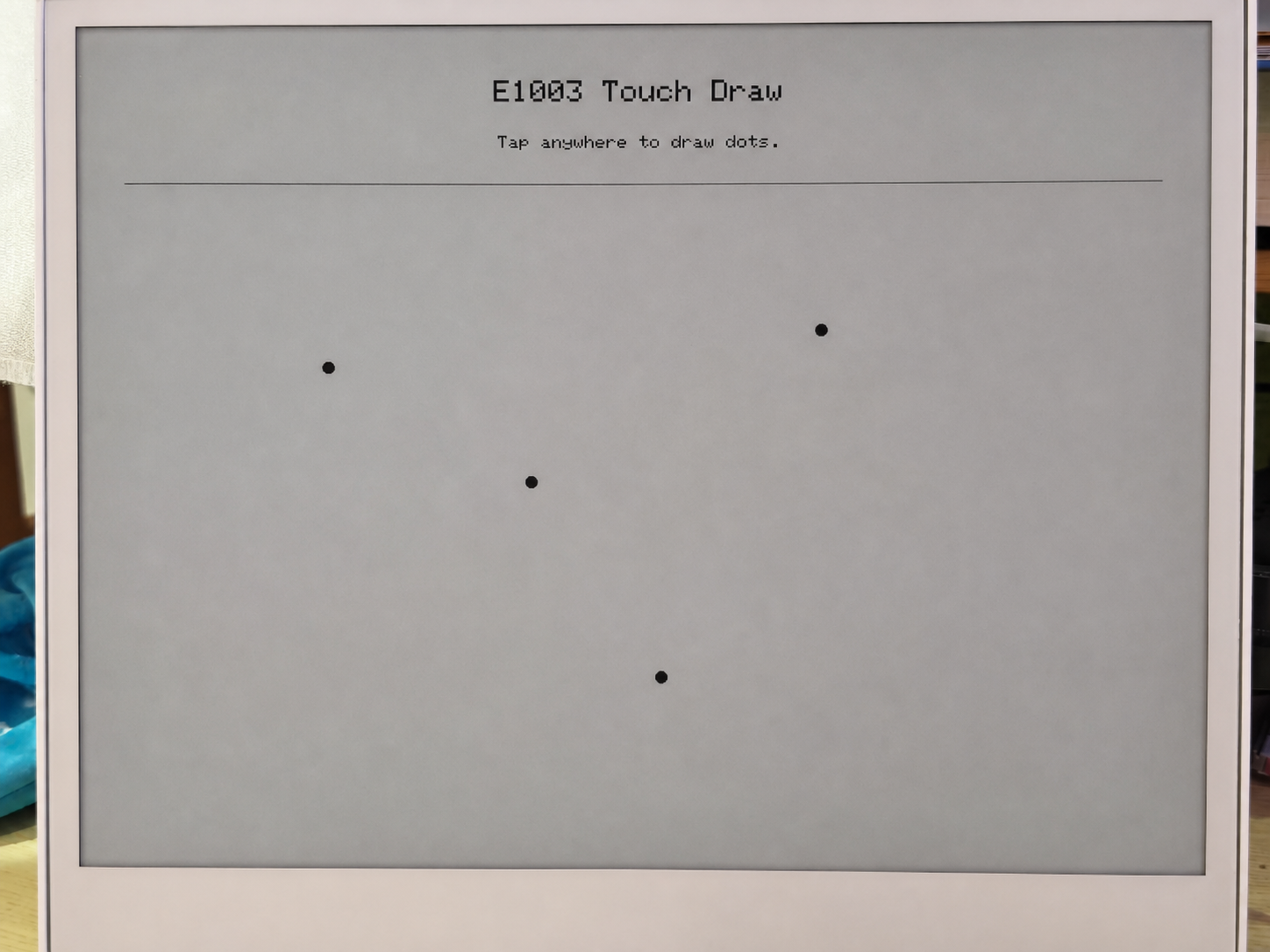
- Dibujar la pantalla de inicio — muestra "E1003 Touch Draw" y un mensaje en la pantalla ePaper.
Bucle de sondeo táctil (loop()):
- Sondear cada 30 ms — lee el registro de estado del GT911 para comprobar si hay un nuevo evento táctil disponible.
- Leer las coordenadas táctiles — extrae las coordenadas X/Y en bruto de los registros de datos de puntos del GT911 y luego las mapea a coordenadas de pantalla usando
mapTouchToDisplay()(que tiene en cuenta cualquier diferencia entre la resolución táctil y la resolución de la pantalla). - Antirrebote y comprobación de distancia — solo se dibuja un nuevo punto si:
- Han pasado al menos 450 ms desde el último dibujo, o
- El punto táctil se ha movido al menos 12 píxeles desde el último punto dibujado.
- Dibujar en la pantalla ePaper —
fillCircle()dibuja un punto negro sólido,drawCircle()añade un anillo de halo gris y luegoupdate()envía el búfer de imagen al panel ePaper.
Cada llamada a update() desencadena una actualización completa de la pantalla ePaper, lo que tarda alrededor de 1–2 segundos en el panel E1003. Esto es normal: ePaper no es una pantalla de actualización rápida. La lógica de antirrebote (DRAW_MIN_MS = 450 ms) está diseñada para evitar saturar el panel con solicitudes de actualización.
Requisitos previos
Antes de ejecutar este sketch:
- Instala la biblioteca Seeed_GFX mediante el Administrador de Bibliotecas de Arduino.
- Establece PSRAM en OPI PSRAM en el menú Tools — sin PSRAM, el búfer de pantalla no se puede asignar y
display_.width()devolverá 0. - Establece Flash Size en 8 MB.
- Selecciona la placa XIAO_ESP32S3.
Salida esperada
========================================
  E1003_TouchDraw - reTerminal E1003
========================================
[display] PSRAM found: yes, free PSRAM: 8159232 bytes
[display] Ready: 1872 x 1404
[touch] GT9xx found at 0x5D, product: 911
[touch] Touch range: 1872 x 1404, display: 1872 x 1404
[touch] Ready.
Después de tocar la pantalla:
[touch] raw=(468,302) screen=(468,302)
[touch] raw=(920,756) screen=(920,756)
[touch] raw=(1400,1100) screen=(1400,1100)
Solución de problemas
P1: La salida serie sigue siendo visible en deep sleep, ¿significa eso que el sketch de bajo consumo no está funcionando?
Esto es normal y no significa que el deep sleep haya fallado.
La salida serie que ves es manejada por el chip puente USB-UART de la placa portadora (no por el propio ESP32-S3). El chip puente se alimenta directamente desde la conexión USB, por lo que permanece activo independientemente de si el ESP32-S3 está despierto o dormido. En realidad, esto es una decisión de diseño deliberada: garantiza que siempre puedas ver la salida serie y cargar nuevo firmware incluso si el dispositivo entra en un ciclo rápido de deep sleep.
Para confirmar que el deep sleep está realmente activo, revisa el registro serie:
- Si ves
[SLEEP] Entering deep sleep now.seguido de silencio, el dispositivo está en deep sleep. - Si ves
[ERROR] deep sleep did not start!, entonces algo salió mal.
P2: ¿Cómo uso correctamente el sketch del RTC para diferentes escenarios?
- Primer arranque
- Reinicio / Nueva alimentación
- Recalibrar
Escenario: Placa completamente nueva o se acaba de reemplazar la batería CR1220.
No necesitas cambiar nada: simplemente sube el sketch tal como está.
En una placa completamente nueva, el indicador interno VL (Voltage Low) del PCF8563 siempre es 1 porque la batería nunca ha alimentado el reloj. El sketch lee VL=1 al inicio y escribe automáticamente la marca de tiempo de compilación en el RTC.
Confirma que tu USER CONFIGURATION se ve así:
#define USE_COMPILE_TIME     // ← enabled ✓
// #define FORCE_SET_TIME   // ← keep commented ✓
→ Haz clic en Upload → Listo.
Escenario: La placa ya estaba funcionando y luego se reinició o se apagó y encendió.
No necesitas hacer nada: simplemente enciéndela.
La batería CR1220 mantiene el PCF8563 en marcha mientras la alimentación principal está apagada. Al inicio, el sketch lee VL=0 (batería en buen estado) y omite la escritura, preservando la hora almacenada. La salida serie mostrará la hora correcta inmediatamente.
Escenario: La hora del RTC es incorrecta y necesita ser recalibrada.
Paso 1 — Forzar sobrescritura. Quita el comentario de FORCE_SET_TIME y luego sube:
#define USE_COMPILE_TIME
#define FORCE_SET_TIME      // ← uncomment this line
→ Haz clic en Upload → Ahora la hora se fuerza a la marca de tiempo de compilación.
Paso 2 — Desactivar la sobrescritura forzada. Inmediatamente vuelve a comentarla y sube de nuevo:
#define USE_COMPILE_TIME
// #define FORCE_SET_TIME   // ← comment it back out
→ Haz clic en Upload → A partir de ahora, cada reinicio preserva la hora almacenada.
Soporte técnico y debate sobre el producto
Gracias por elegir nuestros productos. Estamos aquí para ofrecerte diferentes tipos de soporte y garantizar que tu experiencia con nuestros productos sea lo más fluida posible. Ofrecemos varios canales de comunicación para adaptarnos a diferentes preferencias y necesidades.