Guía de Inicio Rápido de Zigbee para Seeed Studio XIAO ESP32C5 (Arduino)
Este tutorial te guía a través de la implementación de aplicaciones Zigbee en la placa de desarrollo Seeed Studio XIAO ESP32-C5, esta placa combina conectividad Wi-Fi, Bluetooth Low Energy (BLE) y Zigbee, haciéndola perfecta para aplicaciones IoT. Los ejemplos en esta guía utilizan el esp-arduino Zigbee SDK para dar vida a la funcionalidad Zigbee.
Si no has preparado tu Arduino IDE, consulta la Guía de Inicio.
Descripción General de Zigbee
Zigbee es un protocolo de comunicación inalámbrica de bajo consumo y bajo ancho de banda basado en el estándar IEEE 802.15.4. Está diseñado para escenarios IoT como automatización del hogar, ciudades inteligentes y control industrial, ofreciendo capacidades robustas de red en malla para comunicación confiable en entornos dinámicos.
- Proporcionaremos una breve explicación del contenido relacionado con Zigbee. Si quieres ir directamente a los ejemplos de aplicación, también puedes saltar adelante.
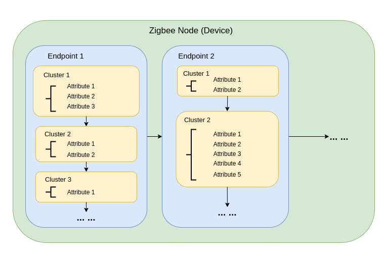
Modelo de Datos Zigbee
La comunicación Zigbee se basa en la Biblioteca de Clústeres Zigbee (ZCL), que define cómo los dispositivos organizan su funcionalidad e interactúan. Los componentes clave incluyen:
-
Tipos de Dispositivos Los dispositivos Zigbee (por ejemplo, interruptores, sensores, luces) están predefinidos con comportamientos específicos, agrupados en Clústeres funcionales.
-
Clústeres Los clústeres son agrupaciones lógicas de:
- Atributos: Representan estados del dispositivo, como brillo o temperatura.
- Comandos: Desencadenan acciones, como encender una luz o establecer el brillo al 50%.
Ejemplos:
- Clúster On/Off: Controla estados binarios como la energía.
- Clúster de Control de Nivel: Ajusta la intensidad o brillo.
- Clúster de Medición de Temperatura: Envía lecturas de temperatura.
- Clúster de Escenas: Guarda y recupera configuraciones preestablecidas.
-
Atributos y Comandos Los atributos almacenan datos del dispositivo (por ejemplo, estado, configuración), mientras que los comandos inician acciones.
Arquitectura de Red Zigbee
Una red Zigbee consiste en tres tipos principales de nodos:
-
Coordinador Zigbee (ZC)
- Sirve como el centro de la red.
- Maneja la creación de la red, autenticación de dispositivos y asignación de direcciones.
- Responsable de inicializar y gestionar la red.
- Cada red Zigbee puede tener solo un Coordinador.
-
Router Zigbee (ZR)
- Extiende el alcance de la red retransmitiendo mensajes entre dispositivos.
- Soporta que dispositivos adicionales se unan a la red.
- Típicamente alimentado por la red eléctrica para asegurar operación constante y retransmisión confiable de mensajes.
- Los Routers alimentados por batería son posibles pero menos comunes debido a mayores demandas de energía.
-
Dispositivo Final Zigbee (ZED)
- Dispositivos ligeros y eficientes en energía que se comunican con un nodo padre (ya sea un Coordinador o Router).
- No enrutan mensajes a otros dispositivos.
- Optimizados para operación con batería y típicamente entran en modos de suspensión para conservar energía.
-
Direccionamiento y Enrutamiento:
- Zigbee utiliza un esquema de direccionamiento de 16 bits. Los dispositivos se comunican a través de una mezcla de direccionamiento directo e indirecto.
- Las decisiones de enrutamiento son tomadas por los Routers usando algoritmos como AODV (Ad hoc On-demand Distance Vector).
-
Gestión de Energía:
- Los Dispositivos Finales Zigbee están optimizados para bajo consumo de energía. A menudo operan en modo de suspensión y solo despiertan cuando es necesario.
- Los Routers y el Coordinador generalmente están alimentados por la red eléctrica para disponibilidad consistente.
Topologías de Red
Zigbee soporta tres topologías de red principales, dependiendo de los requisitos de la aplicación y el entorno:
1. Topología de Malla
-
Un solo Coordinador y múltiples Routers forman una red robusta y auto-reparable.
-
Los dispositivos pueden reencaminar dinámicamente los mensajes si una ruta de comunicación se interrumpe, asegurando alta confiabilidad.
-
Ideal para redes a gran escala que requieren amplia cobertura y redundancia.
-
Características Clave:
- El reencaminamiento dinámico asegura alta confiabilidad.
- Soporta redes grandes con cobertura escalable.
- Los mecanismos de auto-reparación aumentan la tolerancia a fallos.
2. Topología de Árbol
-
El Coordinador actúa como la raíz de una estructura jerárquica, con Routers formando ramas.
-
Cada rama puede tener múltiples Dispositivos Finales o Routers adicionales, creando una estructura similar a un árbol.
-
La comunicación depende de rutas jerárquicas, lo que introduce potenciales puntos únicos de falla.
-
Características Clave:
- Funciona bien para entornos estructurados.
- Más fácil de configurar y gestionar que una red de malla.
- Vulnerable a fallas de rama, que pueden desconectar sub-redes enteras.
3. Topología de Estrella
-
Todos los dispositivos se comunican directamente con el Coordinador.
-
Simple de implementar, pero el Coordinador es un punto único de falla.
-
Mejor adecuado para redes pequeñas donde los dispositivos están ubicados cerca del Coordinador.
-
Características Clave:
- Fácil de configurar y gestionar.
- Escalabilidad limitada debido a restricciones de alcance y capacidad de dispositivos.
- La dependencia del Coordinador para toda la comunicación reduce la tolerancia a fallos.
Comenzar con Arduino Zigbee
Demostraremos la funcionalidad de red Zigbee para ti usando Zigbee_On_Off_Light y Zigbee_On_Off_Switch en el XIAO ESP32-C5 dentro del Arduino IDE.
Preparación del Hardware
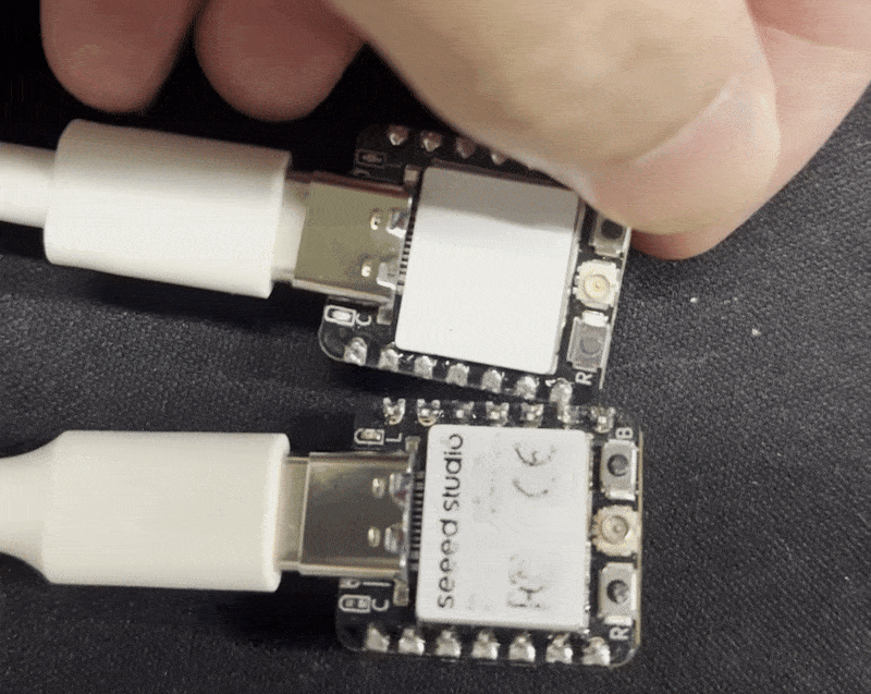
Necesitas preparar dos placas XIAO ESP32-C5.
| Seeed Studio XIAO ESP32-C5 |
|---|
 |
Zigbee_On_Off_Light
Necesitas seleccionar un XIAO ESP32-C5 como el dispositivo de bombilla.
Paso 1. Configurar Modo de Dispositivo Final
Necesitamos configurar el XIAO ESP32-C5 como un Dispositivo Final Zigbee.
- Haz clic en Tools -> Zigbee Mode y selecciona el modo como Zigbee ED (End Device).
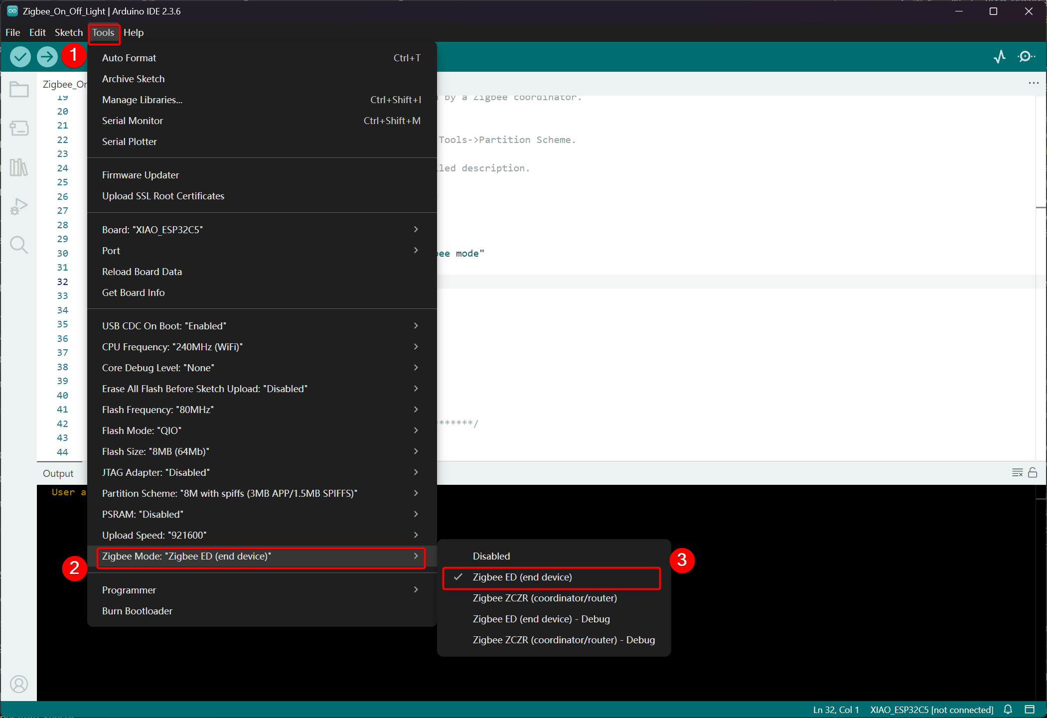
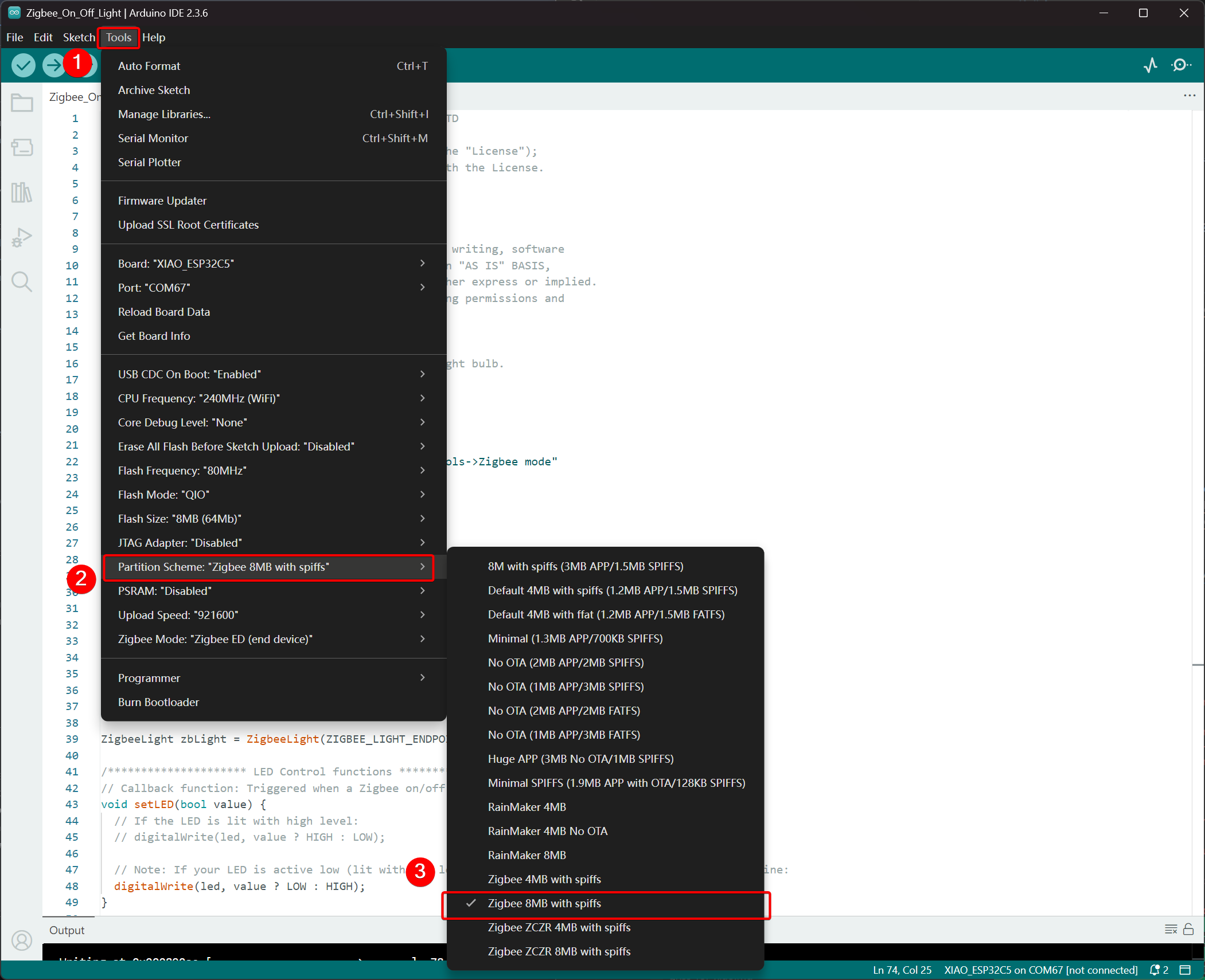
- Selecciona Esquema de Partición, ve a Tools -> Partition Scheme -> Zigbee 8MB with spiffs
La memoria FLASH del XIAO ESP32-C5 es de 8MB. Al seleccionar un esquema de partición, se recomienda elegir Zigbee 8MB with spiffs.
Paso 2. Escribir el código
- Consulta el repositorio oficial de Arduino para obtener ejemplos.
- Alternativamente, puedes seleccionar el ejemplo desde el Arduino IDE a través de la ruta: File -> Examples -> Zigbee -> Zigbee_On_Off_Light.

- Modificar los ejemplos
Para el XIAO ESP32-C5, seleccionamos el LED integrado como la bombilla emisora de luz, y el pin de control es GPIO27.
Zigbee_On_Off_Light.ino
// Copyright 2024 Espressif Systems (Shanghai) PTE LTD
//
// Licensed under the Apache License, Version 2.0 (the "License");
// you may not use this file except in compliance with the License.
// You may obtain a copy of the License at

//     http://www.apache.org/licenses/LICENSE-2.0
//
// Unless required by applicable law or agreed to in writing, software
// distributed under the License is distributed on an "AS IS" BASIS,
// WITHOUT WARRANTIES OR CONDITIONS OF ANY KIND, either express or implied.
// See the License for the specific language governing permissions and
// limitations under the License.

/**
 * @brief This example demonstrates simple Zigbee light bulb.
 *
 * Modified for Single Color LED control.
 */

#ifndef ZIGBEE_MODE_ED
#error "Zigbee end device mode is not selected in Tools->Zigbee mode"
#endif

#include "Zigbee.h"

/* Zigbee light bulb configuration */
#define ZIGBEE_LIGHT_ENDPOINT 10

// =========================================================
// Modification Area: Define your single-color LED pin here
// If your LED is connected to GPIO 2, set it to 2.
// If using the onboard standard LED, LED_BUILTIN can usually be used
// =========================================================
uint8_t led = 27;  // <--- Please modify the number here to your actual GPIO pin number

uint8_t button = BOOT_PIN;

ZigbeeLight zbLight = ZigbeeLight(ZIGBEE_LIGHT_ENDPOINT);

/********************* LED Control functions **************************/
// Callback function: Triggered when a Zigbee on/off command is received
void setLED(bool value) {
  // If the LED is lit with high level:
  // digitalWrite(led, value ? HIGH : LOW);

  // Note: If your LED is active low (lit with low level), use the line below instead of the above line:
  digitalWrite(led, value ? LOW : HIGH);
}

/********************* Arduino functions **************************/
void setup() {
  Serial.begin(115200);

  // Initialize LED pin as output mode
  pinMode(led, OUTPUT);
  // Turn off LED by default (assuming low level means on)
  digitalWrite(led, LOW);

  // Initialize button for factory reset
  pinMode(button, INPUT_PULLUP);

  // Optional: Set Zigbee device name and model (will be displayed in Home Assistant)
  zbLight.setManufacturerAndModel("Espressif", "SingleColorLight");

  // Set callback function for light state change
  zbLight.onLightChange(setLED);

  // Add Endpoint to Zigbee core
  Serial.println("Adding ZigbeeLight endpoint to Zigbee Core");
  Zigbee.addEndpoint(&zbLight);

  // Start Zigbee
  if (!Zigbee.begin()) {
    Serial.println("Zigbee failed to start!");
    Serial.println("Rebooting...");
    ESP.restart();
  }
  Serial.println("Connecting to network");
  while (!Zigbee.connected()) {
    Serial.print(".");
    delay(100);
  }
  Serial.println();
}

void loop() {
  // Check button for factory reset
  if (digitalRead(button) == LOW) {  // Button is pressed
    // Button debounce
    delay(100);
    int startTime = millis();
    while (digitalRead(button) == LOW) {
      delay(50);
      if ((millis() - startTime) > 3000) {
        // If pressed for more than 3 seconds, reset Zigbee and reboot
        Serial.println("Resetting Zigbee to factory and rebooting in 1s.");
        delay(1000);
        Zigbee.factoryReset();
      }
    }
    // Short press of the button: Toggle light state (local control)
    zbLight.setLight(!zbLight.getLightState());
  }
  delay(100);
}
- Subir el código. Dado que está configurado para encenderse en nivel bajo por defecto, presiona el botón de reset después de subir el código, y el LED integrado se encenderá.
Lógica de Implementación
- Verificación de Modo
#ifndef ZIGBEE_MODE_ED
#error "Zigbee end device mode is not selected..."
#endif
Esto fuerza la selección del modo "End Device" en Tools → Zigbee mode del Arduino IDE. Las bombillas Zigbee típicamente actúan como dispositivos finales de bajo consumo, en lugar de Routers o Coordinadores.
- Incluir Archivo de Cabecera
#include "Zigbee.h"
Importa la biblioteca principal de Zigbee proporcionada por Espressif, que contiene todas las clases y funciones relacionadas con Zigbee.
- Definición de Configuración
#define ZIGBEE_LIGHT_ENDPOINT 10
Define el número de Endpoint de Zigbee como 10. Un dispositivo Zigbee puede tener múltiples endpoints, y la funcionalidad de la bombilla se asigna al endpoint 10 aquí.
- Área Modificable por el Usuario (Parte Más Importante)
uint8_t led = 27;        // Modify this to the actual GPIO pin connected to your LED
uint8_t button = BOOT_PIN;  // Usually GPIO0, used for factory reset
-
led = 27: El pin GPIO que controla el LED monocromático. Por favor modifica este número según el cableado de tu hardware. -
button = BOOT_PIN: Usualmente el botón BOOT (GPIO0) en la placa de desarrollo ESP32, usado para resetear la configuración de Zigbee con una pulsación larga.
- Crear Objeto de Bombilla Zigbee
ZigbeeLight zbLight = ZigbeeLight(ZIGBEE_LIGHT_ENDPOINT);
Crea un objeto Zigbee Light que implementa el estándar Zigbee HA (Home Automation) OnOff Cluster para bombillas, soportando control remoto de encendido/apagado.
- Función de Callback de Control de LED
void setLED(bool value) {
  digitalWrite(led, value ? LOW : HIGH);
}
Esta función se llama automáticamente cuando se recibe un comando de encendido/apagado desde la red Zigbee.
- El código actual asume que tu LED es activo bajo (común cuando un LED externo en una placa de desarrollo ESP32 está conectado a GND a través de una resistencia).
- Si tu LED es activo alto (por ejemplo, conectado directamente a VCC y se enciende al poner el GPIO en bajo), modifícalo a la línea comentada a continuación:
digitalWrite(led, value ? HIGH : LOW);
- Explicación Detallada de la Función setup()
void setup() {
  Serial.begin(115200);                    // Enable serial debugging with baud rate 115200

  pinMode(led, OUTPUT);                    // Set the LED pin as output
  digitalWrite(led, LOW);                  // Turn off the LED by default (assuming active low, write LOW to ensure it's off)

  pinMode(button, INPUT_PULLUP);           // Set the button pin as input with pull-up resistor

  zbLight.setManufacturerAndModel("Espressif", "SingleColorLight");
  // Set the device manufacturer and model for friendly display on platforms like Home Assistant

  zbLight.onLightChange(setLED);
  // Key step: Bind the callback function for switch state changes, which calls setLED() when a Zigbee command is received

  Zigbee.addEndpoint(&zbLight);
  // Add the bulb endpoint to the Zigbee core

  if (!Zigbee.begin()) { ... ESP.restart(); }
  // Start the Zigbee stack; restart if it fails

  while (!Zigbee.connected()) { ... }
  // Wait for successful joining of the Zigbee network (pairing completed), print a dot every 100ms
}
- Explicación Detallada de la Función loop()
void loop() {
  if (digitalRead(button) == LOW) {        // Detect button press (low level)
    delay(100);                            // Simple debounce
    int startTime = millis();

    while (digitalRead(button) == LOW) {   // Continuously detect if the button is still pressed
      if ((millis() - startTime) > 3000) { // Long press for more than 3 seconds
        Zigbee.factoryReset();             // Factory reset Zigbee configuration (clear pairing information)
        delay(1000);
        // The device will automatically restart and enter pairing mode again
      }
    }

    // If short press: manually control the light's on/off state locally
    zbLight.setLight(!zbLight.getLightState());
    // This triggers the callback setLED() simultaneously to turn the light on/off locally
  }

  delay(100);
}
Zigbee_On_Off_Switch
Selecciona otro XIAO ESP32-C5 como el interruptor. Formará una red Zigbee con el dispositivo de bombilla anterior y luego controlará el estado de encendido/apagado de la bombilla.
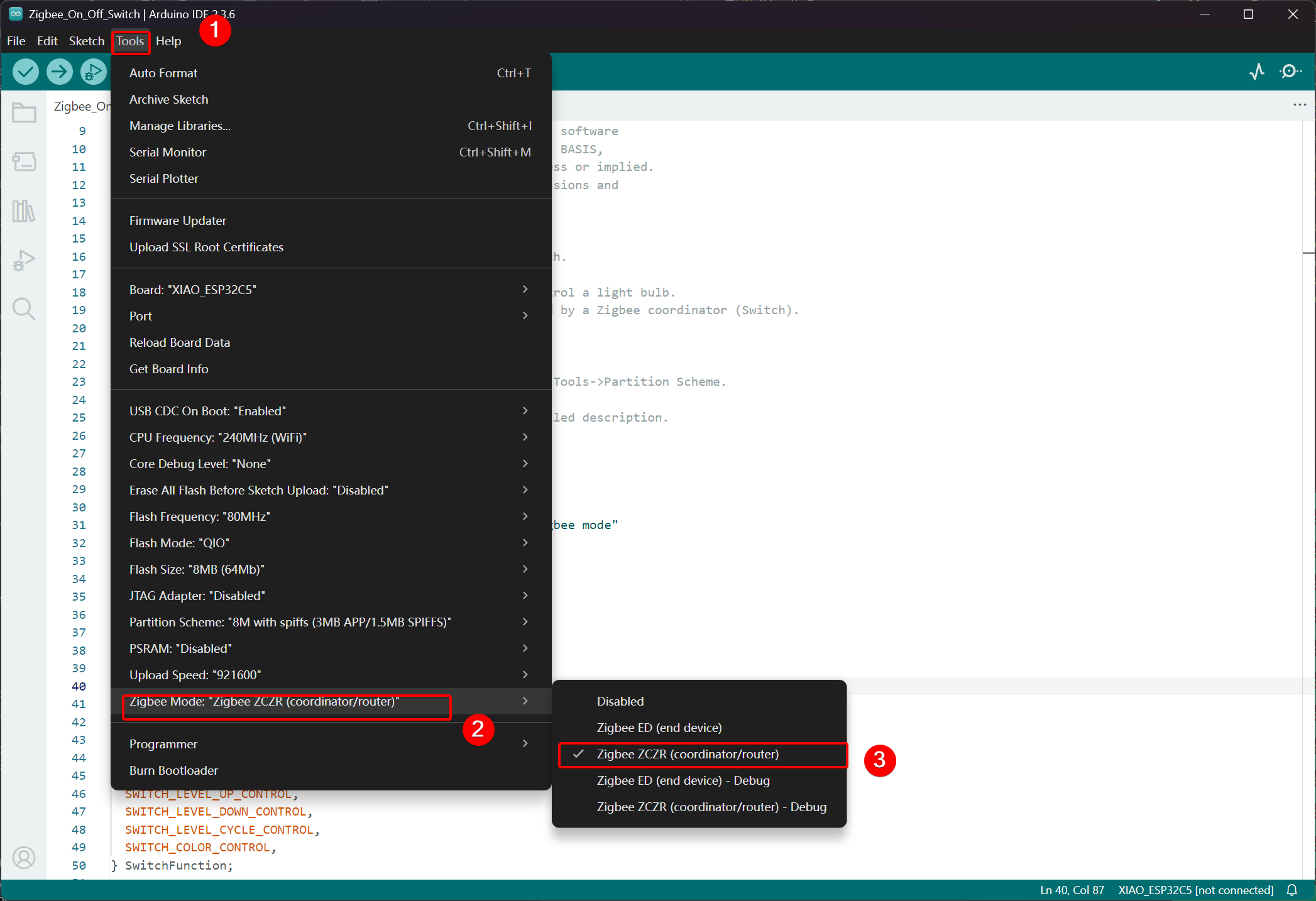
Paso 1. Configurar en Modo Coordinador
- Haz clic en Tools -> Zigbee Mode y selecciona el modo como Zigbee ZCZR (Coordinator/Router).
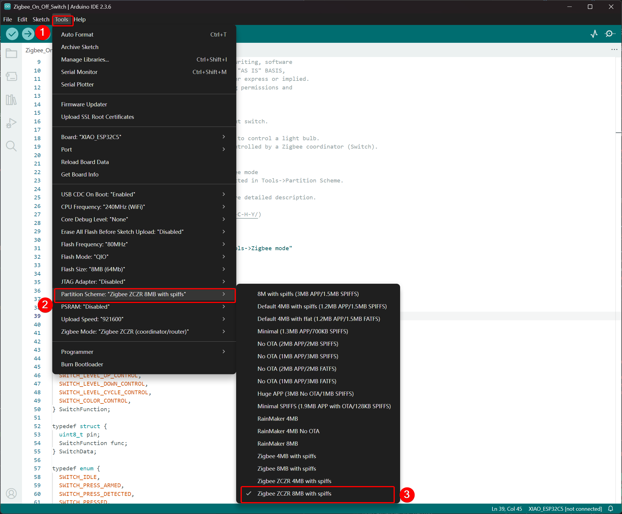
- Seleccionar Esquema de Partición, ve a Tools -> Partition Scheme y elige Zigbee 8MB ZCZR with spiffs.
La memoria FLASH del XIAO ESP32-C5 es de 8MB. Al seleccionar un esquema de partición, se recomienda elegir Zigbee 8MB ZCZR with spiffs.
Paso 2. Escribir el código
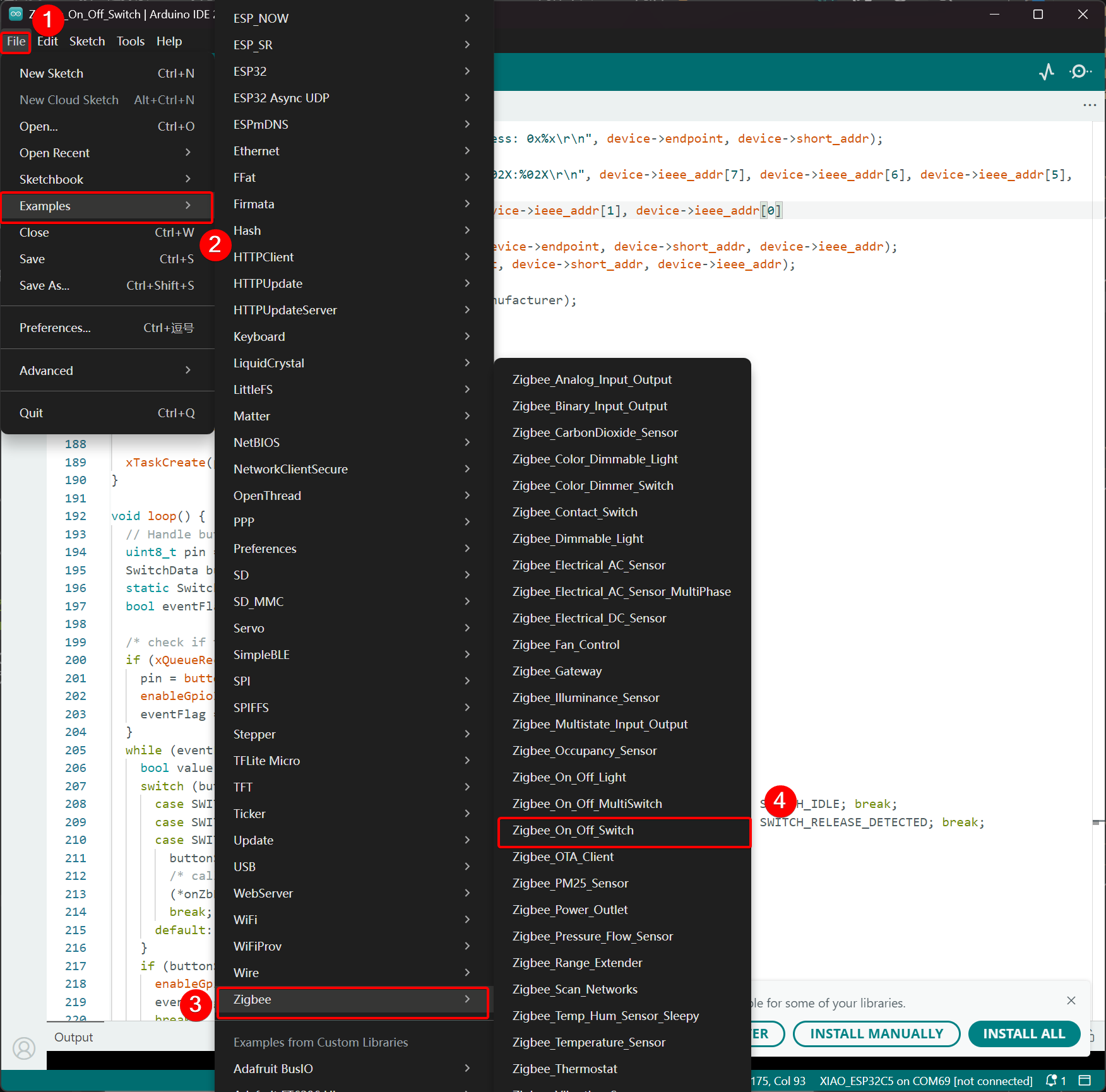
- Ve al repositorio oficial de Arduino para obtener el código de ejemplo.
- Alternativamente, puedes seleccionar el ejemplo desde el IDE de Arduino a través de la ruta: File -> Examples -> Zigbee -> Zigbee_On_Off_Swicth.
- Seleccionamos el botón BOOT como el interruptor. Para el XIAO ESP32-C5, el botón BOOT corresponde al pin GPIO28.
Zigbee_On_Off_Switch.ino
// Copyright 2024 Espressif Systems (Shanghai) PTE LTD
//
// Licensed under the Apache License, Version 2.0 (the "License");
// you may not use this file except in compliance with the License.
// You may obtain a copy of the License at
//
//     http://www.apache.org/licenses/LICENSE-2.0
//
// Unless required by applicable law or agreed to in writing, software
// distributed under the License is distributed on an "AS IS" BASIS,
// WITHOUT WARRANTIES OR CONDITIONS OF ANY KIND, either express or implied.
// See the License for the specific language governing permissions and
// limitations under the License.

/**
 * @brief This example demonstrates simple Zigbee light switch.
 *
 * The example demonstrates how to use Zigbee library to control a light bulb.
 * The light bulb is a Zigbee end device, which is controlled by a Zigbee coordinator (Switch).
 * Button switch and Zigbee runs in separate tasks.
 *
 * Proper Zigbee mode must be selected in Tools->Zigbee mode
 * and also the correct partition scheme must be selected in Tools->Partition Scheme.
 *
 * Please check the README.md for instructions and more detailed description.
 *
 * Created by Jan Procházka (https://github.com/P-R-O-C-H-Y/)
 */

#ifndef ZIGBEE_MODE_ZCZR
#error "Zigbee coordinator mode is not selected in Tools->Zigbee mode"
#endif

#include "Zigbee.h"

/* Zigbee switch configuration */
#define SWITCH_ENDPOINT_NUMBER 5

#define GPIO_INPUT_IO_TOGGLE_SWITCH BOOT_PIN
#define PAIR_SIZE(TYPE_STR_PAIR)    (sizeof(TYPE_STR_PAIR) / sizeof(TYPE_STR_PAIR[0]))

typedef enum {
  SWITCH_ON_CONTROL,
  SWITCH_OFF_CONTROL,
  SWITCH_ONOFF_TOGGLE_CONTROL,
  SWITCH_LEVEL_UP_CONTROL,
  SWITCH_LEVEL_DOWN_CONTROL,
  SWITCH_LEVEL_CYCLE_CONTROL,
  SWITCH_COLOR_CONTROL,
} SwitchFunction;

typedef struct {
  uint8_t pin;
  SwitchFunction func;
} SwitchData;

typedef enum {
  SWITCH_IDLE,
  SWITCH_PRESS_ARMED,
  SWITCH_PRESS_DETECTED,
  SWITCH_PRESSED,
  SWITCH_RELEASE_DETECTED,
} SwitchState;

static SwitchData buttonFunctionPair[] = {{GPIO_INPUT_IO_TOGGLE_SWITCH, SWITCH_ONOFF_TOGGLE_CONTROL}};

ZigbeeSwitch zbSwitch = ZigbeeSwitch(SWITCH_ENDPOINT_NUMBER);

static bool light_state = false;

/********************* Zigbee functions **************************/
static void onZbButton(SwitchData *button_func_pair) {
  if (button_func_pair->func == SWITCH_ONOFF_TOGGLE_CONTROL) {
    // Send toggle command to the light
    Serial.println("Toggling light");
    zbSwitch.lightToggle();
  }
}

static void onLightStateChange(bool state) {
  if (state != light_state) {
    light_state = state;
    Serial.printf("Light state changed to %d\r\n", state);
  }
}

/********************* Periodic task ***************************/
void periodicTask(void *arg) {
  while (true) {
    // print the bound lights every 10 seconds
    static uint32_t lastPrint = 0;
    if (millis() - lastPrint > 10000) {
      lastPrint = millis();
      zbSwitch.printBoundDevices(Serial);
    }

    // Poll light state every second
    static uint32_t lastPoll = 0;
    if (millis() - lastPoll > 1000) {
      lastPoll = millis();
      zbSwitch.getLightState();
    }
    vTaskDelay(1000 / portTICK_PERIOD_MS);
  }
}

/********************* GPIO functions **************************/
static QueueHandle_t gpio_evt_queue = NULL;

static void IRAM_ATTR onGpioInterrupt(void *arg) {
  xQueueSendFromISR(gpio_evt_queue, (SwitchData *)arg, NULL);
}

static void enableGpioInterrupt(bool enabled) {
  for (int i = 0; i < PAIR_SIZE(buttonFunctionPair); ++i) {
    if (enabled) {
      enableInterrupt((buttonFunctionPair[i]).pin);
    } else {
      disableInterrupt((buttonFunctionPair[i]).pin);
    }
  }
}

/********************* Arduino functions **************************/
void setup() {
  Serial.begin(115200);

  //Optional: set Zigbee device name and model
  zbSwitch.setManufacturerAndModel("Espressif", "ZigbeeSwitch");

  //Optional to allow multiple light to bind to the switch
  zbSwitch.allowMultipleBinding(true);

  zbSwitch.onLightStateChange(onLightStateChange);

  //Add endpoint to Zigbee Core
  Serial.println("Adding ZigbeeSwitch endpoint to Zigbee Core");
  Zigbee.addEndpoint(&zbSwitch);

  //Open network for 180 seconds after boot
  Zigbee.setRebootOpenNetwork(180);

  // Init button switch
  for (int i = 0; i < PAIR_SIZE(buttonFunctionPair); i++) {
    pinMode(buttonFunctionPair[i].pin, INPUT_PULLUP);
    /* create a queue to handle gpio event from isr */
    gpio_evt_queue = xQueueCreate(10, sizeof(SwitchData));
    if (gpio_evt_queue == 0) {
      Serial.println("Queue creating failed, rebooting...");
      ESP.restart();
    }
    attachInterruptArg(buttonFunctionPair[i].pin, onGpioInterrupt, (void *)(buttonFunctionPair + i), FALLING);
  }

  // When all EPs are registered, start Zigbee with ZIGBEE_COORDINATOR mode
  if (!Zigbee.begin(ZIGBEE_COORDINATOR)) {
    Serial.println("Zigbee failed to start!");
    Serial.println("Rebooting...");
    ESP.restart();
  }

  Serial.println("Waiting for Light to bound to the switch");
  //Wait for switch to bound to a light:
  while (!zbSwitch.bound()) {
    Serial.printf(".");
    delay(500);
  }

  // Optional: List all bound devices and read manufacturer and model name
  std::list<zb_device_params_t *> boundLights = zbSwitch.getBoundDevices();
  for (const auto &device : boundLights) {
    Serial.printf("Device on endpoint %d, short address: 0x%x\r\n", device->endpoint, device->short_addr);
    Serial.printf(
      "IEEE Address: %02X:%02X:%02X:%02X:%02X:%02X:%02X:%02X\r\n", device->ieee_addr[7], device->ieee_addr[6], device->ieee_addr[5], device->ieee_addr[4],
      device->ieee_addr[3], device->ieee_addr[2], device->ieee_addr[1], device->ieee_addr[0]
    );
    char *manufacturer = zbSwitch.readManufacturer(device->endpoint, device->short_addr, device->ieee_addr);
    char *model = zbSwitch.readModel(device->endpoint, device->short_addr, device->ieee_addr);
    if (manufacturer != nullptr) {
      Serial.printf("Light manufacturer: %s\r\n", manufacturer);
    }
    if (model != nullptr) {
      Serial.printf("Light model: %s\r\n", model);
    }
  }

  Serial.println();

  xTaskCreate(periodicTask, "periodicTask", 1024 * 4, NULL, 10, NULL);
}

void loop() {
  // Handle button switch in loop()
  uint8_t pin = 0;
  SwitchData buttonSwitch;
  static SwitchState buttonState = SWITCH_IDLE;
  bool eventFlag = false;

  /* check if there is any queue received, if yes read out the buttonSwitch */
  if (xQueueReceive(gpio_evt_queue, &buttonSwitch, portMAX_DELAY)) {
    pin = buttonSwitch.pin;
    enableGpioInterrupt(false);
    eventFlag = true;
  }
  while (eventFlag) {
    bool value = digitalRead(pin);
    switch (buttonState) {
      case SWITCH_IDLE:           buttonState = (value == LOW) ? SWITCH_PRESS_DETECTED : SWITCH_IDLE; break;
      case SWITCH_PRESS_DETECTED: buttonState = (value == LOW) ? SWITCH_PRESS_DETECTED : SWITCH_RELEASE_DETECTED; break;
      case SWITCH_RELEASE_DETECTED:
        buttonState = SWITCH_IDLE;
        /* callback to button_handler */
        (*onZbButton)(&buttonSwitch);
        break;
      default: break;
    }
    if (buttonState == SWITCH_IDLE) {
      enableGpioInterrupt(true);
      eventFlag = false;
      break;
    }
    vTaskDelay(10 / portTICK_PERIOD_MS);
  }
}
- Sube el código y abre el Monitor Serie; la información de red se imprimirá. Para el efecto final, por favor salta a Resultado
Lógica de Implementación
- Verificación de Modo
#ifndef ZIGBEE_MODE_ZCZR
#error "Zigbee coordinator mode is not selected in Tools->Zigbee mode"
#endif
El interruptor en este ejemplo actúa como un Coordinador Zigbee (ZC/ZR), responsable de formar la red y controlar otros dispositivos.
- Incluir Archivo de Cabecera
#include "Zigbee.h"
Importa la librería principal de Zigbee proporcionada por Espressif, que contiene todas las clases y funciones necesarias para las operaciones Zigbee.
- Definiciones de Configuración
#define SWITCH_ENDPOINT_NUMBER 5
#define GPIO_INPUT_IO_TOGGLE_SWITCH BOOT_PIN
SWITCH_ENDPOINT_NUMBER 5: Define el número de endpoint (5) utilizado por la funcionalidad del interruptor Zigbee.GPIO_INPUT_IO_TOGGLE_SWITCH BOOT_PIN: Establece el pin del botón físico al pin BOOT (generalmente GPIO0). Este botón activará una acción de alternancia.
- Estructuras de Datos y Configuración del Botón
typedef enum { ... } SwitchFunction;
typedef struct { uint8_t pin; SwitchFunction func; } SwitchData;

static SwitchData buttonFunctionPair[] = {{GPIO_INPUT_IO_TOGGLE_SWITCH, SWITCH_ONOFF_TOGGLE_CONTROL}};
- Define las posibles funciones del interruptor (alternar, encender, apagar, control de nivel, etc.).
- El array
buttonFunctionPairmapea los pines físicos a sus funciones. Actualmente, solo un botón está configurado: el pin BOOT realiza una acción de alternancia cuando se presiona.
- Crear Objeto Interruptor Zigbee
ZigbeeSwitch zbSwitch = ZigbeeSwitch(SWITCH_ENDPOINT_NUMBER);
Crea un objeto ZigbeeSwitch que implementa un dispositivo interruptor Zigbee On/Off estándar, capaz de enviar comandos a bombillas vinculadas a través del enlace Zigbee.
- Funciones de Callback Zigbee
static void onZbButton(SwitchData *button_func_pair) {
  if (button_func_pair->func == SWITCH_ONOFF_TOGGLE_CONTROL) {
    zbSwitch.lightToggle();  // Send toggle command to all bound lights
  }
}

static void onLightStateChange(bool state) {
  // Called when a bound light reports a state change
  Serial.printf("Light state changed to %d\r\n", state);
}
onZbButton: Se ejecuta cuando se detecta una pulsación válida del botón; envía un comando de alternancia a todas las luces vinculadas.onLightStateChange: Callback activado cuando cualquier luz vinculada reporta su nuevo estado encendido/apagado (útil para sincronización).
- Tarea Periódica
void periodicTask(void *arg) {
  while (true) {
    // Every 10 seconds: print all currently bound devices
    // Every 1 second: poll the current state of bound lights
    vTaskDelay(1000 / portTICK_PERIOD_MS);
  }
}
Una tarea FreeRTOS separada que imprime periódicamente información de dispositivos vinculados y consulta estados de luces para mantener el coordinador sincronizado.
- Interrupción GPIO y Manejo de Cola
static QueueHandle_t gpio_evt_queue = NULL;

static void IRAM_ATTR onGpioInterrupt(void *arg) {
  xQueueSendFromISR(gpio_evt_queue, (SwitchData *)arg, NULL);
}
- Utiliza una cola FreeRTOS para pasar de forma segura eventos de pulsación de botón desde la ISR (rutina de servicio de interrupción) al bucle principal.
- La interrupción se adjunta al flanco descendente en el pin del botón para detección rápida.
- Explicación Detallada de la Función setup()
void setup() {
  Serial.begin(115200);

  zbSwitch.setManufacturerAndModel("Espressif", "ZigbeeSwitch");
  zbSwitch.allowMultipleBinding(true);  // Allow controlling multiple lights simultaneously
  zbSwitch.onLightStateChange(onLightStateChange);

  Zigbee.addEndpoint(&zbSwitch);

  Zigbee.setRebootOpenNetwork(180);  // Open network for pairing for 180 seconds after boot

  // Initialize button pins and attach interrupts
  pinMode(... , INPUT_PULLUP);
  attachInterruptArg(... , FALLING);

  if (!Zigbee.begin(ZIGBEE_COORDINATOR)) { ... ESP.restart(); }

  // Block until at least one light is bound
  while (!zbSwitch.bound()) { Serial.print("."); delay(500); }

  // Print detailed information about all bound lights (address, manufacturer, model)
  zbSwitch.printBoundDevices(Serial);

  // Create periodic task
  xTaskCreate(periodicTask, "periodicTask", 1024 * 4, NULL, 10, NULL);
}
- Configura las propiedades del dispositivo interruptor y permite múltiples enlaces.
- Abre la red durante 180 segundos para facilitar el emparejamiento fácil de bombillas.
- Inicia Zigbee en modo Coordinador.
- Espera hasta que al menos una luz se vincule exitosamente, luego imprime información detallada de enlace.
- Lanza la tarea de monitoreo periódico.
- Explicación Detallada de la Función loop()
void loop() {
  // Receive button events from queue
  if (xQueueReceive(gpio_evt_queue, &buttonSwitch, portMAX_DELAY)) {
    // Disable further interrupts to prevent bounce interference
    enableGpioInterrupt(false);

    // State machine for reliable button detection:
    // - Detect press → confirm sustained press → detect release → execute action
    static SwitchState buttonState = SWITCH_IDLE;
    // ... state transitions ...

    if (buttonState == SWITCH_IDLE) {
      // Button fully released → execute toggle command
      onZbButton(&buttonSwitch);
      // Re-enable interrupts for next press
      enableGpioInterrupt(true);
    }
  }
}
- Implementa un manejador de botón robusto con anti-rebote usando una máquina de estados.
- Asegura un ciclo completo de presionar y soltar antes de enviar el comando de alternancia.
- Previene la re-entrada de interrupción durante el procesamiento para operación estable.
Resultado
Conecta las dos placas XIAO ESP32-C5 a tu computadora y abre el Monitor Serie. Si el dispositivo bombilla imprime Connecting to network, indica que se ha unido a la red Zigbee, y el dispositivo interruptor imprimirá la información de los dispositivos que se han unido a la red. Cuando presiones el botón BOOT en el dispositivo interruptor, el LED USER a bordo del dispositivo bombilla alternará.
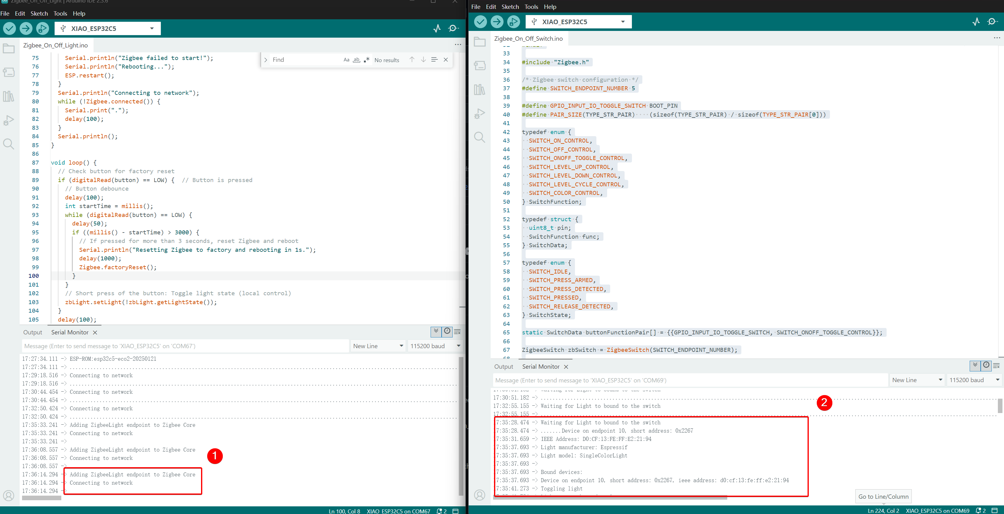
- Efecto de Control, cuando se presiona el botón BOOT, el LED USER en el otro XIAO ESP32-C5 alternará.
Soporte Técnico y Discusión de Productos
¡Gracias por elegir nuestros productos! Estamos aquí para brindarte diferentes tipos de soporte para asegurar que tu experiencia con nuestros productos sea lo más fluida posible. Ofrecemos varios canales de comunicación para atender diferentes preferencias y necesidades.