Uso del sensor integrado del Seeed Studio XIAO nRF54L15 Sense
El siguiente código de ejemplo está diseñado para PlatformIO, pero también es compatible con el nRF Connect SDK.
Basado en VS Code, si quieres usar el siguiente caso en el nRF Connect SDK, consulta la conexión proporcionada, agrega el archivo app.overlay y modifica el contenido en prj.conf
XIAO nRF54L15 Agregar archivo overlay y modificar archivo conf.
IMU del XIAO nRF54L15 Sense
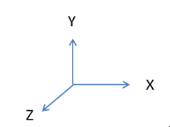
Los sensores IMU de 6 ejes (Unidad de Medición Inercial) como el LSM6DS3TR-C integran acelerómetros y giroscopios para medir el movimiento y la orientación de un objeto en el espacio tridimensional. Específicamente, el LSM6DS3TR-C tiene las siguientes características:
Función del acelerómetro:
- Mide la aceleración de un objeto a lo largo de los ejes X, Y y Z. Es capaz de detectar el movimiento del objeto (por ejemplo, reposo, aceleración, desaceleración) y cambios de inclinación (por ejemplo, ángulo del objeto).
- Se puede usar para detectar la marcha, cambios de posición, vibraciones, etc.
Función del giroscopio:
- Mide la velocidad angular de un objeto alrededor de los ejes X, Y y Z, es decir, la rotación del objeto.
- Se puede usar para detectar rotación, velocidad de rotación y cambio de dirección.
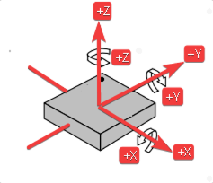
- El ángulo del eje X (Roll) es el ángulo en la dirección de rotación alrededor del eje X.
- El ángulo del eje Y (Pitch) es el ángulo en la dirección de rotación alrededor del eje Y.
- El ángulo del eje Z (Yaw) es el ángulo en la dirección de rotación alrededor del eje Z.
Controlador IMU
Para simplificar tu experiencia de desarrollo y asegurar un inicio rápido con este programa IMU, hemos aprovechado la plataforma PlatformIO para escribir el código de controlador necesario. PlatformIO ofrece un entorno integral y eficiente para el desarrollo embebido, convirtiéndolo en una opción ideal para el XIAO nRF54L15 Sense.
Antes de continuar, asegúrate de que tu entorno de desarrollo esté configurado correctamente. Si aún no has agregado la placa de desarrollo Seeed Studio XIAO nRF54L15 a tu configuración de PlatformIO, consulta este enlace para obtener instrucciones detalladas sobre cómo configurarla. Este paso crucial permitirá que PlatformIO reconozca y compile correctamente el código para tu placa.
Una vez que tu entorno esté listo, el controlador IMU te permitirá leer datos de sensor en bruto del LSM6DS3TR-C. Estos datos incluyen:
-
Valores en bruto del acelerómetro (accel raw): Representando la aceleración a lo largo de los ejes X, Y y Z.
-
Valores en bruto del giroscopio (gyro raw): Indicando la velocidad angular alrededor de los ejes X, Y y Z.
-
Contador de disparos (trig_cnt): Un contador que se incrementa con cada nueva muestra de datos.
Descarga el repositorio a C:\Users\xxx\.platformio\platforms y abre la carpeta examples\zephyr-imu en VS Code. Luego haz clic en main.c, y verás el siguiente código:
#include <zephyr/kernel.h>
#include <zephyr/device.h>
#include <zephyr/drivers/sensor.h>
#include <zephyr/logging/log.h>

LOG_MODULE_REGISTER(zephyr_imu, LOG_LEVEL_INF);

static inline float out_ev(struct sensor_value *val)
{
	return (val->val1 + (float)val->val2 / 1000000);
}

static void fetch_and_display(const struct device *dev)
{
	struct sensor_value x, y, z;
	static int trig_cnt;

	trig_cnt++;

	/* lsm6dsl accel */
	sensor_sample_fetch_chan(dev, SENSOR_CHAN_ACCEL_XYZ);
	sensor_channel_get(dev, SENSOR_CHAN_ACCEL_X, &x);
	sensor_channel_get(dev, SENSOR_CHAN_ACCEL_Y, &y);
	sensor_channel_get(dev, SENSOR_CHAN_ACCEL_Z, &z);

	LOG_INF("accel x:%f m/s^2 y:%f m/s^2 z:%f m/s^2",
			(double)out_ev(&x), (double)out_ev(&y), (double)out_ev(&z));

	/* lsm6dsl gyro */
	sensor_sample_fetch_chan(dev, SENSOR_CHAN_GYRO_XYZ);
	sensor_channel_get(dev, SENSOR_CHAN_GYRO_X, &x);
	sensor_channel_get(dev, SENSOR_CHAN_GYRO_Y, &y);
	sensor_channel_get(dev, SENSOR_CHAN_GYRO_Z, &z);

	LOG_INF("gyro x:%f rad/s y:%f rad/s z:%f rad/s",
			(double)out_ev(&x), (double)out_ev(&y), (double)out_ev(&z));

	LOG_INF("trig_cnt:%d", trig_cnt);
}

static int set_sampling_freq(const struct device *dev)
{
	int ret = 0;
	struct sensor_value odr_attr;

	/* set accel/gyro sampling frequency to 12.5 Hz */
	odr_attr.val1 = 12.5;
	odr_attr.val2 = 0;

	ret = sensor_attr_set(dev, SENSOR_CHAN_ACCEL_XYZ,
			SENSOR_ATTR_SAMPLING_FREQUENCY, &odr_attr);
	if (ret != 0) {
		LOG_ERR("Cannot set sampling frequency for accelerometer.");
		return ret;
	}

	ret = sensor_attr_set(dev, SENSOR_CHAN_GYRO_XYZ,
			SENSOR_ATTR_SAMPLING_FREQUENCY, &odr_attr);
	if (ret != 0) {
		LOG_ERR("Cannot set sampling frequency for gyro.");
		return ret;
	}

	return 0;
}

#ifdef CONFIG_LSM6DSL_TRIGGER
static void trigger_handler(const struct device *dev,
			    const struct sensor_trigger *trig)
{
	fetch_and_display(dev);
}

static void test_trigger_mode(const struct device *dev)
{
	struct sensor_trigger trig;

	if (set_sampling_freq(dev) != 0) {
		return;
	}

	trig.type = SENSOR_TRIG_DATA_READY;
	trig.chan = SENSOR_CHAN_ACCEL_XYZ;

	if (sensor_trigger_set(dev, &trig, trigger_handler) != 0) {
		LOG_ERR("Could not set sensor type and channel");
		return;
	}
}

#else
static void test_polling_mode(const struct device *dev)
{
	if (set_sampling_freq(dev) != 0) {
		return;
	}

	while (1) {
		fetch_and_display(dev);
		k_sleep(K_MSEC(1000));
	}
}
#endif

int main(void)
{
	const struct device *const dev = DEVICE_DT_GET(DT_ALIAS(imu0));

	if (!device_is_ready(dev)) {
		LOG_ERR("%s: device not ready.", dev->name);
		return 0;
	}

#ifdef CONFIG_LSM6DSL_TRIGGER
	LOG_INF("Testing LSM6DSL sensor in trigger mode.");
	test_trigger_mode(dev);
#else
	LOG_INF("Testing LSM6DSL sensor in polling mode.");
	test_polling_mode(dev);
#endif
	return 0;
}
Ahora, conecta tu XIAO nRF54L15 a tu computadora vía USB. En VS Code:
-
Compilar: Haz clic en el ícono "Build" (marca de verificación) en la barra de herramientas de PlatformIO en la parte inferior de VS Code, o usa la barra lateral de PlatformIO: PROJECT TASKS -> nombre_de_tu_proyecto -> General -> Build.
-
Cargar: Después de una compilación exitosa, haz clic en el ícono "Upload" (flecha derecha) en la barra de herramientas de PlatformIO, o usa la barra lateral de PlatformIO: PROJECT TASKS -> nombre_de_tu_proyecto -> General -> Upload.
Después de una carga exitosa, deberías ver una salida similar al ejemplo a continuación en el Monitor de Dispositivo de PlatformIO (PROJECT TASKS -> nombre_de_tu_proyecto -> General -> Monitor). Esta salida serial muestra lecturas en tiempo real del acelerómetro y giroscopio, proporcionando información clave sobre el movimiento y orientación de tu dispositivo.

Salida de datos IMU en tiempo real del Monitor de Dispositivo de PlatformIO, mostrando lecturas en bruto del acelerómetro y giroscopio.
Estos datos en bruto forman la base para varias aplicaciones, desde la detección simple de movimiento hasta el seguimiento complejo de orientación, aplicando algoritmos apropiados (por ejemplo, filtrado, fusión de sensores).
MIC del XIAO nRF54L15 Sense
El MSM261DGT006 es un Micrófono Digital (DMIC) que produce datos de Modulación de Densidad de Pulsos (PDM), haciéndolo adecuado para interfaz digital directa con microcontroladores como el XIAO nRF54L15 Sense. Nuestro controlador DMIC está específicamente diseñado para manejar esta salida PDM, convertirla en muestras de audio utilizables y procesarla para varias aplicaciones.
El controlador inicia el micrófono, establece la frecuencia de muestreo apropiada (por ejemplo, 16000 Hz para audio estándar) y configura la frecuencia del reloj PDM. Luego lee continuamente buffers de muestras del micrófono, permitiendo la captura de audio en tiempo real.
La salida del controlador DMIC, cuando se ve en el Monitor de Dispositivo de PlatformIO, proporciona información crucial sobre la operación del micrófono y los datos de audio entrantes. Los mensajes clave que observarás incluyen:
-
DMIC sample=:Indica el inicio del proceso de muestreo DMIC. -
PCM output rate:16000, channels: 1: Confirma la configuración de salida de audio, típicamente una frecuencia de muestreo de 16 kHz y audio de un solo canal (mono). -
dmic_nrf_pdm:PDM clock frequency: 1280000, actual PCM rate: 16000: Muestra la frecuencia interna del reloj PDM y la frecuencia de muestreo de audio PCM resultante. -
got buffer 0x... of 3200 bytes:Confirma que el controlador recibió exitosamente un buffer de datos de audio del micrófono. Se muestran la dirección hexadecimal (ej., 0x20004C8) y el tamaño en bytes (ej., 3200 bytes). Estos buffers contienen las muestras de audio sin procesar que luego pueden ser procesadas o analizadas. -
dmix_sample: Exiting:Indica que el proceso de muestreo DMIC ha sido detenido.
A continuación se muestra un ejemplo de la salida típica que puedes esperar ver en el Monitor de Dispositivo de PlatformIO cuando el controlador DMIC está funcionando, ilustrando la captura y almacenamiento exitoso de datos de audio.
Controlador DMIC
Estos datos de audio sin procesar, una vez capturados, pueden ser utilizados para una amplia gama de aplicaciones, incluyendo comandos de voz, detección de eventos sonoros, monitoreo de ruido ambiental y tareas más complejas de procesamiento de audio.
El siguiente ejemplo de código demuestra cómo grabar audio usando el botón pulsador en la placa XIAO nRF54L15 y guardar el archivo WAV grabado en una computadora.
#include <zephyr/kernel.h>
#include <zephyr/device.h>
#include <zephyr/drivers/gpio.h>
#include <zephyr/audio/dmic.h>
#include <zephyr/sys/util.h>
#include <zephyr/logging/log.h>
#include <zephyr/drivers/uart.h>

LOG_MODULE_REGISTER(mic_capture_sample, LOG_LEVEL_INF);

#define RECORD_TIME_S  10                // Recording duration (seconds)
#define SAMPLE_RATE_HZ 16000            // Sample rate (Hz)
#define SAMPLE_BIT_WIDTH 16             // Sample bit width (bits)
#define BYTES_PER_SAMPLE (SAMPLE_BIT_WIDTH / 8) // Bytes per sample

#define READ_TIMEOUT_MS 1000            // DMIC read timeout (ms)
#define CHUNK_DURATION_MS 100           // Duration of each chunk (ms)
#define CHUNK_SIZE_BYTES  (BYTES_PER_SAMPLE * (SAMPLE_RATE_HZ * CHUNK_DURATION_MS) / 1000) // Chunk size (bytes)
#define CHUNK_COUNT       8             // Number of blocks in memory pool
#define TOTAL_CHUNKS      (RECORD_TIME_S * 1000 / CHUNK_DURATION_MS) // Total number of chunks

static const struct device *const dmic_dev = DEVICE_DT_GET(DT_ALIAS(dmic20)); // DMIC device handle
static const struct gpio_dt_spec led = GPIO_DT_SPEC_GET(DT_ALIAS(led0), gpios); // LED device descriptor
static const struct gpio_dt_spec button = GPIO_DT_SPEC_GET(DT_ALIAS(sw0), gpios); // Button device descriptor
static const struct device *const console_dev = DEVICE_DT_GET(DT_CHOSEN(zephyr_console)); // Console UART device

K_MEM_SLAB_DEFINE_STATIC(mem_slab, CHUNK_SIZE_BYTES, CHUNK_COUNT, 4); // Audio data memory pool
K_MSGQ_DEFINE(audio_msgq, sizeof(void *), CHUNK_COUNT, 4);

static K_SEM_DEFINE(tx_done_sem, 0, 1); // Button semaphore
static K_SEM_DEFINE(button_sem, 0, 1); // UART TX done semaphore

static const uint8_t packet_start[] = {0xAA, 0x55, 'S', 'T', 'A', 'R', 'T'}; // Packet start marker
static const uint8_t packet_end[] = {0xAA, 0x55, 'E', 'N', 'D'};             // Packet end marker

static struct gpio_callback button_cb_data;

/**
 * @brief UART callback function
 *
 * @param dev UART device pointer
 * @param evt UART event
 * @param user_data User data (unused)
 */
static void uart_tx_callback(const struct device *dev, struct uart_event *evt, void *user_data)
{
    if (evt->type == UART_TX_DONE) {
        k_sem_give(&tx_done_sem);
    }
}

/**
 * @brief Button interrupt callback function
 *
 * @param dev Button device pointer
 * @param cb  Callback structure pointer
 * @param pins Triggered pins
 */
void button_pressed(const struct device *dev, struct gpio_callback *cb, uint32_t pins)
{
    k_sem_give(&button_sem);
}

/**
 * @brief Send a data packet via UART (polling, for small packets)
 *
 * @param data Data pointer
 * @param len  Data length
 */
static void send_packet_poll(const uint8_t *data, size_t len)
{
    for (size_t i = 0; i < len; i++) {
        uart_poll_out(console_dev, data[i]);
    }
}

/**
 * @brief UART writer thread function
 *
 * This thread continuously reads audio data from the message queue and sends it via UART.
 * It waits for the semaphore to signal that the previous transmission is done before sending the next chunk.
 */
void uart_writer_thread(void *p1, void *p2, void *p3)
{
    uart_callback_set(console_dev, uart_tx_callback, NULL);

    while (true) {
        void *buffer;
        k_msgq_get(&audio_msgq, &buffer, K_FOREVER);

        if (buffer == NULL) {
            send_packet_poll(packet_end, sizeof(packet_end));
            continue;
        }

        uart_tx(console_dev, buffer, CHUNK_SIZE_BYTES, SYS_FOREVER_US);
        k_sem_take(&tx_done_sem, K_FOREVER);

        k_mem_slab_free(&mem_slab, buffer);
    }
}


K_THREAD_DEFINE(uart_writer_tid, 2048, uart_writer_thread, NULL, NULL, NULL,
                K_PRIO_COOP(7), 0, 0);

static struct pcm_stream_cfg stream_cfg = {
    .pcm_rate = SAMPLE_RATE_HZ,
    .pcm_width = SAMPLE_BIT_WIDTH,
    .block_size = CHUNK_SIZE_BYTES,
    .mem_slab = &mem_slab,
}; // PCM stream configuration

static struct dmic_cfg dmic_config = {
    .io = {
        .min_pdm_clk_freq = 1000000,
        .max_pdm_clk_freq = 3500000,
        .min_pdm_clk_dc = 40,
        .max_pdm_clk_dc = 60,
    },
    .streams = &stream_cfg,
    .channel = {
        .req_num_streams = 1,
        .req_num_chan = 1,
    },
}; // DMIC configuration

/**
 * @brief Record audio from DMIC and stream it via UART
 *
 * @return 0 on success, negative error code on failure
 */
static int record_and_stream_audio(void)
{
    int ret;
    void *buffer;
    uint32_t size;

    k_msgq_purge(&audio_msgq);

    ret = dmic_configure(dmic_dev, &dmic_config);
    if (ret < 0) {
        LOG_ERR("Failed to configure DMIC: %d", ret);
        return ret;
    }

    ret = dmic_trigger(dmic_dev, DMIC_TRIGGER_START);
    if (ret < 0) {
        LOG_ERR("Failed to start DMIC: %d", ret);
        return ret;
    }

    ret = dmic_read(dmic_dev, 0, &buffer, &size, READ_TIMEOUT_MS);
    if (ret < 0) {
        LOG_WRN("Failed to read discard chunk: %d", ret);
    } else {
        k_mem_slab_free(&mem_slab, buffer);
    }

    send_packet_poll(packet_start, sizeof(packet_start));

    for (int i = 0; i < TOTAL_CHUNKS; i++) {
        ret = dmic_read(dmic_dev, 0, &buffer, &size, READ_TIMEOUT_MS);
        if (ret < 0) {
            LOG_ERR("Failed to read from DMIC: %d", ret);
            break;
        }

        ret = k_msgq_put(&audio_msgq, &buffer, K_MSEC(500));
        if (ret != 0) {
            LOG_ERR("Failed to queue buffer. UART thread might be too slow.");
            k_mem_slab_free(&mem_slab, buffer);
            break;
        }
    }

    (void)dmic_trigger(dmic_dev, DMIC_TRIGGER_STOP);

    void *end_marker = NULL;
    k_msgq_put(&audio_msgq, &end_marker, K_NO_WAIT);

    LOG_INF("Audio capture finished and data queued.");
    return 0;
}

/**
 * @brief Main function, initializes peripherals and waits for button to trigger recording in a loop
 *
 * @return Always returns 0
 */
int main(void)
{
    int ret;

 // Check if all required devices are ready
    if (!device_is_ready(dmic_dev) || !device_is_ready(led.port) ||
        !device_is_ready(button.port) || !device_is_ready(console_dev)) {
        LOG_ERR("A required device is not ready.");
        return -ENODEV;
    }

 // Configure DMIC channel mapping
    dmic_config.channel.req_chan_map_lo = dmic_build_channel_map(0, 0, PDM_CHAN_LEFT);

    // Configure LED as output
    ret = gpio_pin_configure_dt(&led, GPIO_OUTPUT_ACTIVE);
    if (ret < 0) { return ret; }

    // Configure button as input and enable interrupt
    ret = gpio_pin_configure_dt(&button, GPIO_INPUT);
    if (ret < 0) { return ret; }
    ret = gpio_pin_interrupt_configure_dt(&button, GPIO_INT_EDGE_TO_ACTIVE);
    if (ret < 0) { return ret; }
    gpio_init_callback(&button_cb_data, button_pressed, BIT(button.pin));
    gpio_add_callback(button.port, &button_cb_data);

    LOG_INF("Zephyr Audio Streamer Ready.");
    LOG_INF("Press button SW0 to start recording...");

    // Main loop, wait for button to trigger recording
    while (1) {
        k_sem_take(&button_sem, K_FOREVER);
        LOG_INF("Button pressed, starting capture...");

        gpio_pin_set_dt(&led, 0);
        record_and_stream_audio();
        gpio_pin_set_dt(&led, 1);

        LOG_INF("\nPress button SW0 to start recording again...");
    }

    return 0;
}
A continuación, abre la terminal en el directorio de la carpeta scripts y realiza las siguientes operaciones, siempre que el programa ya haya sido grabado.
Paso 1:
python3 -m pip install pyserial
Paso 2:
python record.py -p /dev/cu.usbmodemA0CBDDC33 -o output.wav -b 921600
En este comando python record.py -p **/dev/cu.usbmodemA0CBDDC33** -o output.wav -b 921600, necesitas reemplazarlo con tu puerto serie para usarlo.
Paso 3:
- Después de ejecutar el comando, se te pedirá que presiones el botón para grabar sonido.
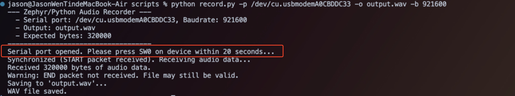
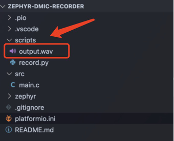
Después de grabar el audio, el archivo se guardará en scripts
Soporte Técnico y Discusión de Productos
¡Gracias por elegir nuestros productos! Estamos aquí para brindarle diferentes tipos de soporte para asegurar que su experiencia con nuestros productos sea lo más fluida posible. Ofrecemos varios canales de comunicación para satisfacer diferentes preferencias y necesidades.