
Primeros pasos con Seeed Studio XIAO nRF54L15(Sense)
| Seeed Studio XIAO nRF54L15 | Seeed Studio XIAO nRF54L15 Sense |
|---|---|
 |  |
Introducción
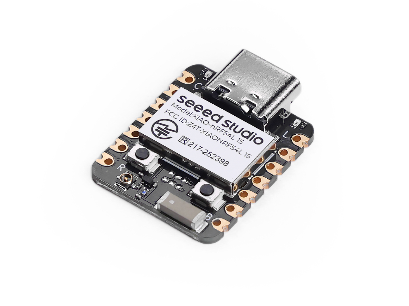
La Seeed Studio XIAO nRF54L15 es una placa de desarrollo compacta y de alto rendimiento que incorpora el avanzado chip Nordic nRF54L15. Este SoC de próxima generación integra una radio multiprotocolo de 2,4 GHz de ultra bajo consumo con un MCU que contiene un procesador Arm® Cortex®-M33 de 128 MHz y un coprocesador RISC-V de 128 MHz. Ofrece memoria escalable de hasta 1,5 MB de NVM y 256 KB de RAM, y un diseño interno de ultra bajo consumo que prolonga significativamente la vida útil de la batería. Su potente radio es compatible con Bluetooth® 6.0 (incluido Channel Sounding), Matter, Thread, Zigbee y modos propietarios de alta velocidad en 2,4 GHz de hasta 4 Mbps. La placa incluye un conjunto completo de periféricos, un coprocesador RISC-V de 128 MHz integrado y funciones de seguridad avanzadas como el aislamiento TrustZone® y la protección del motor criptográfico. Con gestión de batería de ion-litio integrada, la XIAO nRF54L15 es ideal para soluciones IoT compactas, seguras y de alta eficiencia energética, como wearables inteligentes, sensores industriales y HMI avanzadas.
Especificaciones
| Elemento | XIAO nRF54L15 | XIAO nRF54L15 Sense |
|---|---|---|
| MCU | Arm Cortex-M33 128 MHz RISC-V coprocessor 128 MHz FLPR | Arm Cortex-M33 128 MHz RISC-V coprocessor 128 MHz FLPR |
| Conectividad inalámbrica | Bluetooth LE 6.0(incluye Channel Sounding) | Bluetooth LE 6.0(incluye Channel Sounding) |
| Memoria | NVM 1.5 MB + RAM256 KB | NVM 1.5 MB + RAM256 KB |
| Sensor integrado | N/A | IMU de 6 DOF (LSM6DS3TR-C) Micrófono (MSM261DGT006) |
| Potencia de transmisión (TX) | +8 dBm | +8 dBm |
| Sensibilidad de recepción (RX) | -96 dBm | -96 dBm |
| Periféricos destacados | ADC de 14 bits, Global RTC | ADC de 14 bits, Global RTC |
| Alimentación | Alimentación mediante interfaz USB Type-C | Alimentación mediante interfaz USB Type-C |
| Temperatura de funcionamiento | -40 a 105°C | -40 a 105°C |
| Rango de voltaje de alimentación | 3.7 a 5 V | 3.7 a 5 V |
| ESB y protocolos propietarios de 2,4 GHz | hasta 4 Mbps | hasta 4 Mbps |
| Detectores de manipulación | SÍ | SÍ |
| Bluetooth channel sounding | SÍ | SÍ |
Características
- CPU potente: procesador Arm® Cortex®-M33 de 128 MHz con soporte para instrucciones DSP y operaciones de coma flotante FPU, arquitectura RISC de 32 bits y coprocesador RISC-V integrado de 128 MHz.
- Ultra bajo consumo: diseñado para un consumo de energía ultra bajo superior, prolonga significativamente la vida útil de la batería e incluye una gestión de energía avanzada.
- Transmisión inalámbrica multimodo: transceptor inalámbrico multiprotocolo de 2,4 GHz integrado que admite Bluetooth Low Energy (incluido Channel Sounding), 802.15.4-2020, Matter, Thread, Zigbee y modos propietarios de 2,4 GHz (hasta 4 Mbps).
- Seguridad robusta: funciones de seguridad avanzadas que incluyen aislamiento TrustZone®, detección de manipulación y protección contra fugas de canal en el lado del motor de cifrado.
- Ricos recursos integrados: configuraciones de memoria escalables de hasta 1,5 MB de NVM y 256 KB de RAM que proporcionan un amplio espacio de almacenamiento.
- Interfaces abundantes: conjunto completo de periféricos que incluye el nuevo Global RTC (disponible en modo System OFF), ADC de 14 bits e interfaces serie de alta velocidad. Gestión de batería de litio integrada.
Descripción general del hardware
- XIAO nRF54L15
- XIAO nRF54L15 Sense
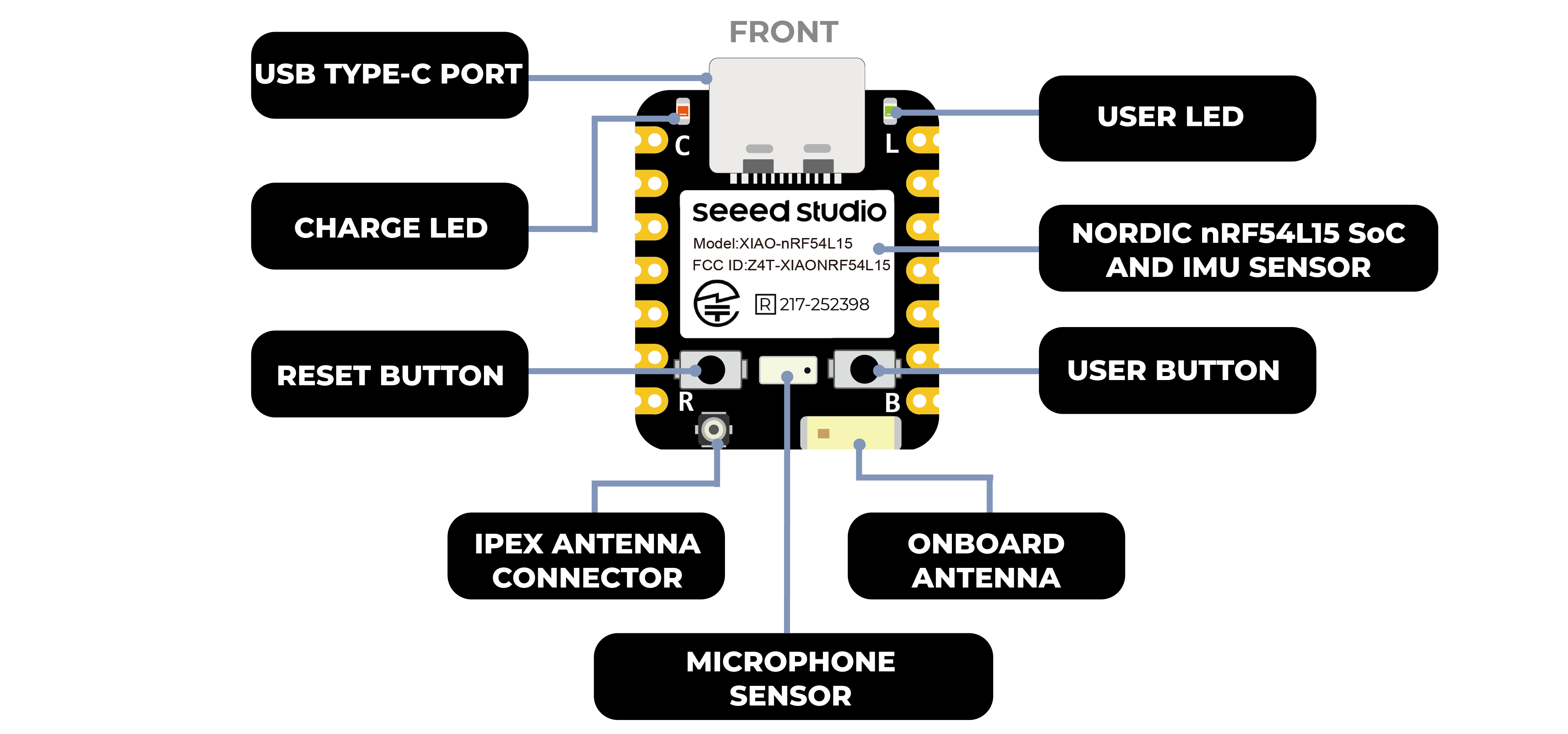
| Diagrama de indicación frontal de XIAO nRF54L15 |
|---|
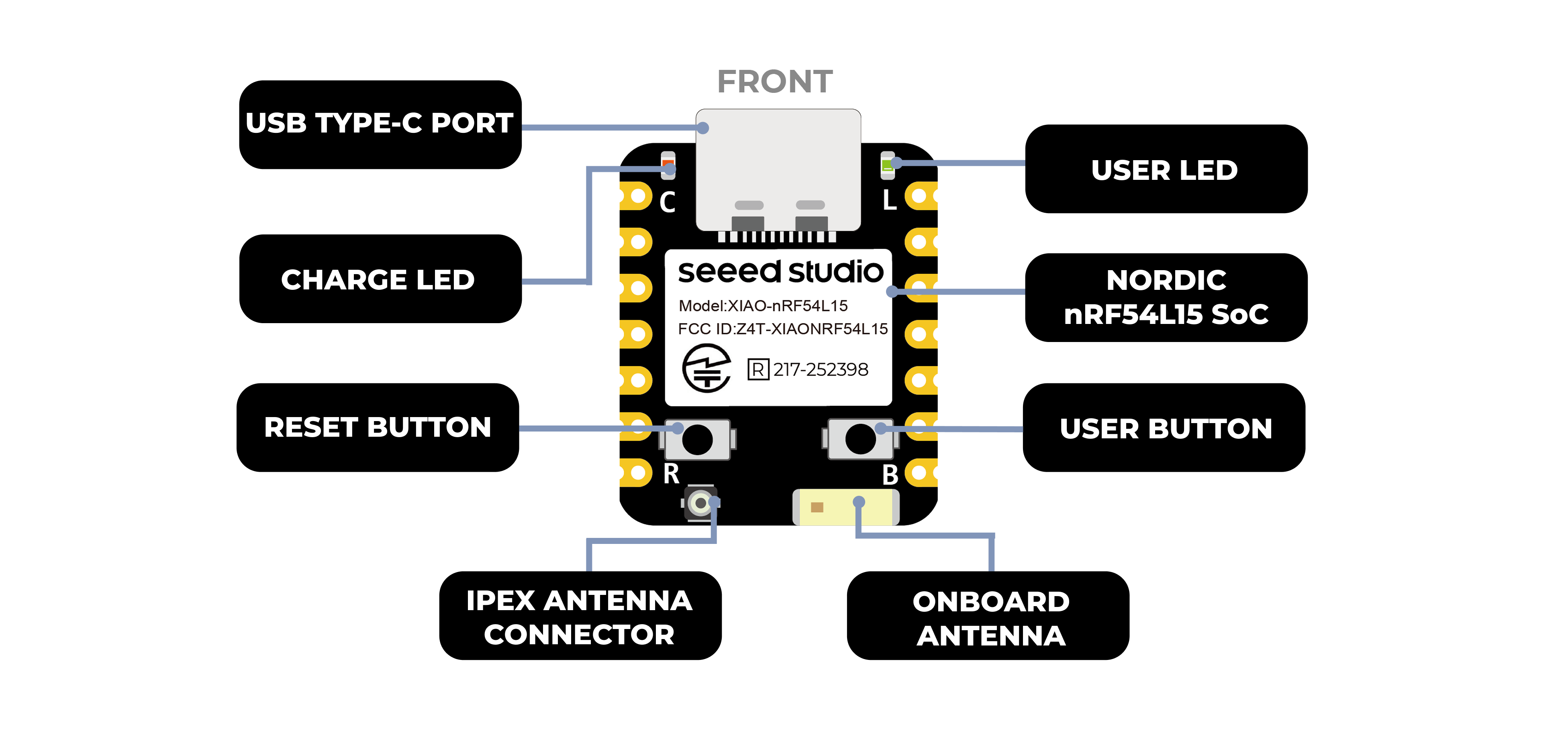 |
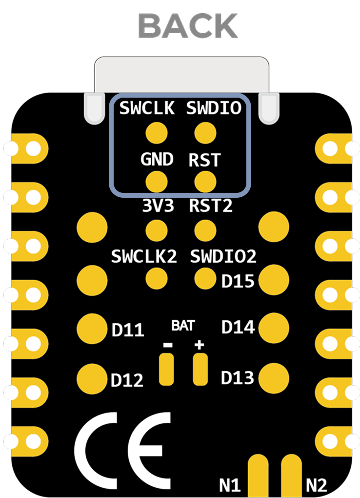
| Diagrama de indicación trasera de XIAO nRF54L15 |
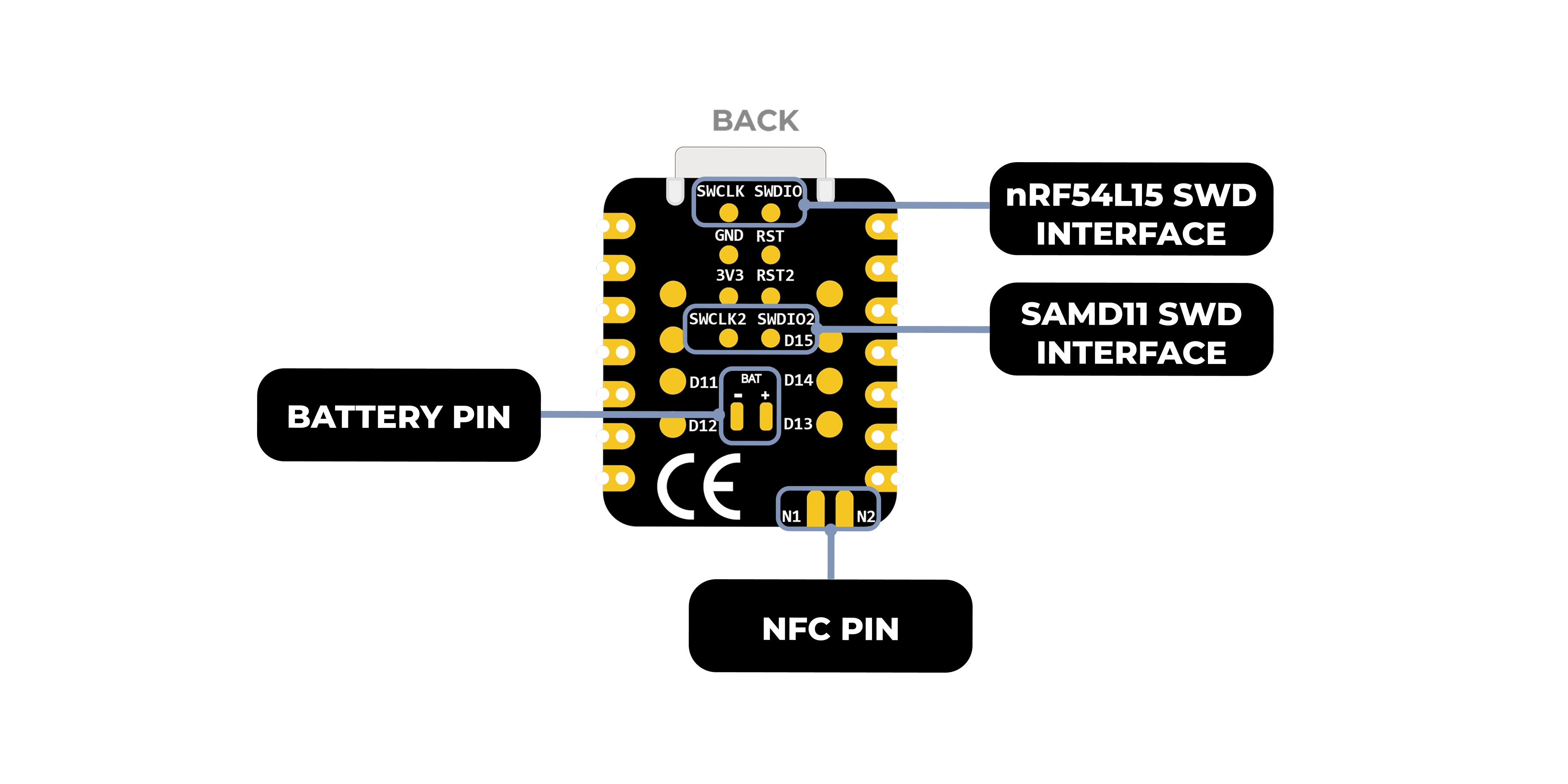 |
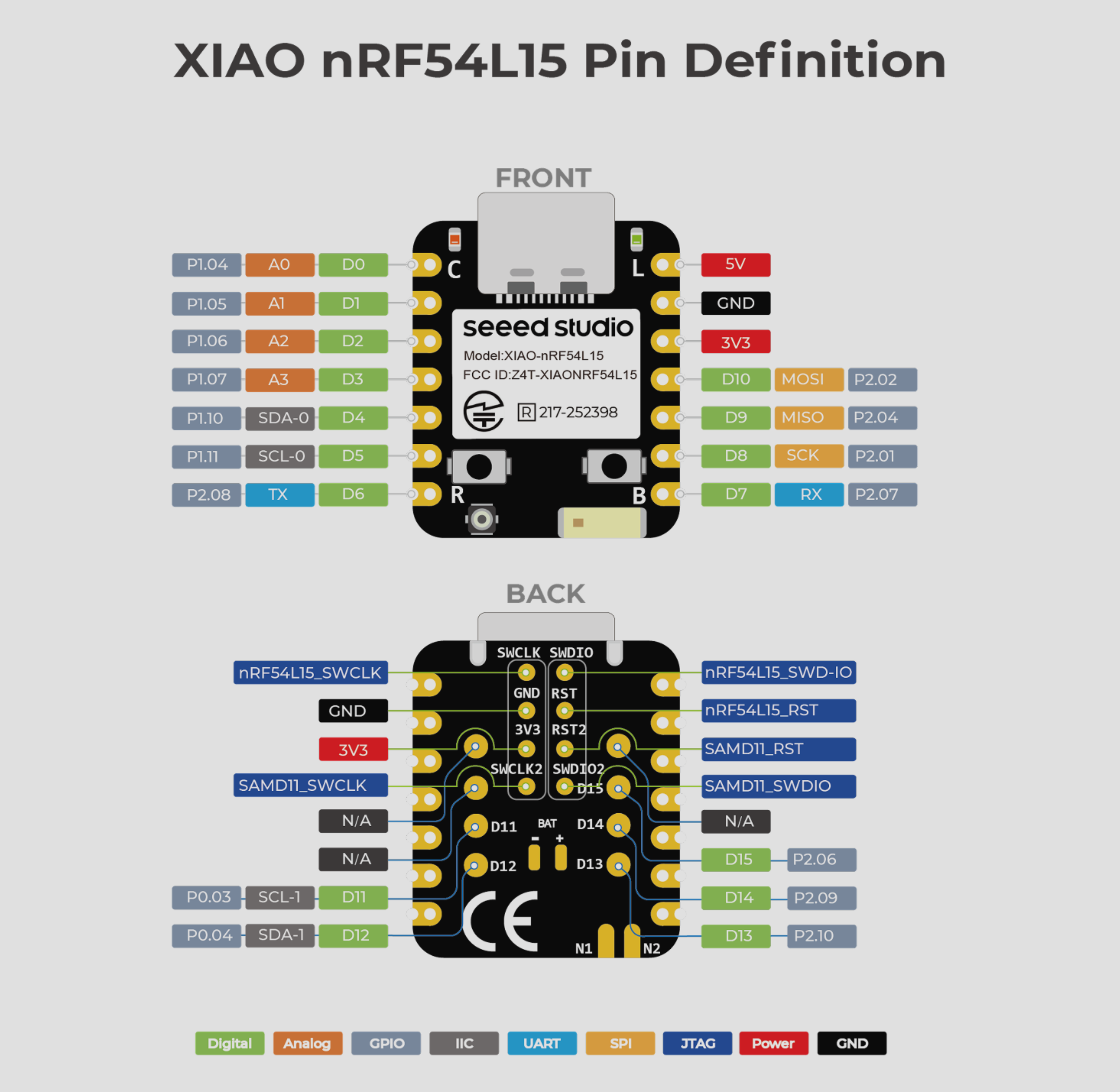
| Lista de pines de XIAO nRF54L15 |
 |
| Diagrama de indicación frontal de XIAO nRF54L15 Sense |
|---|
 |
| Diagrama de indicación trasera de XIAO nRF54L15 Sense |
|
| Lista de pines de XIAO nRF54L15 Sense |
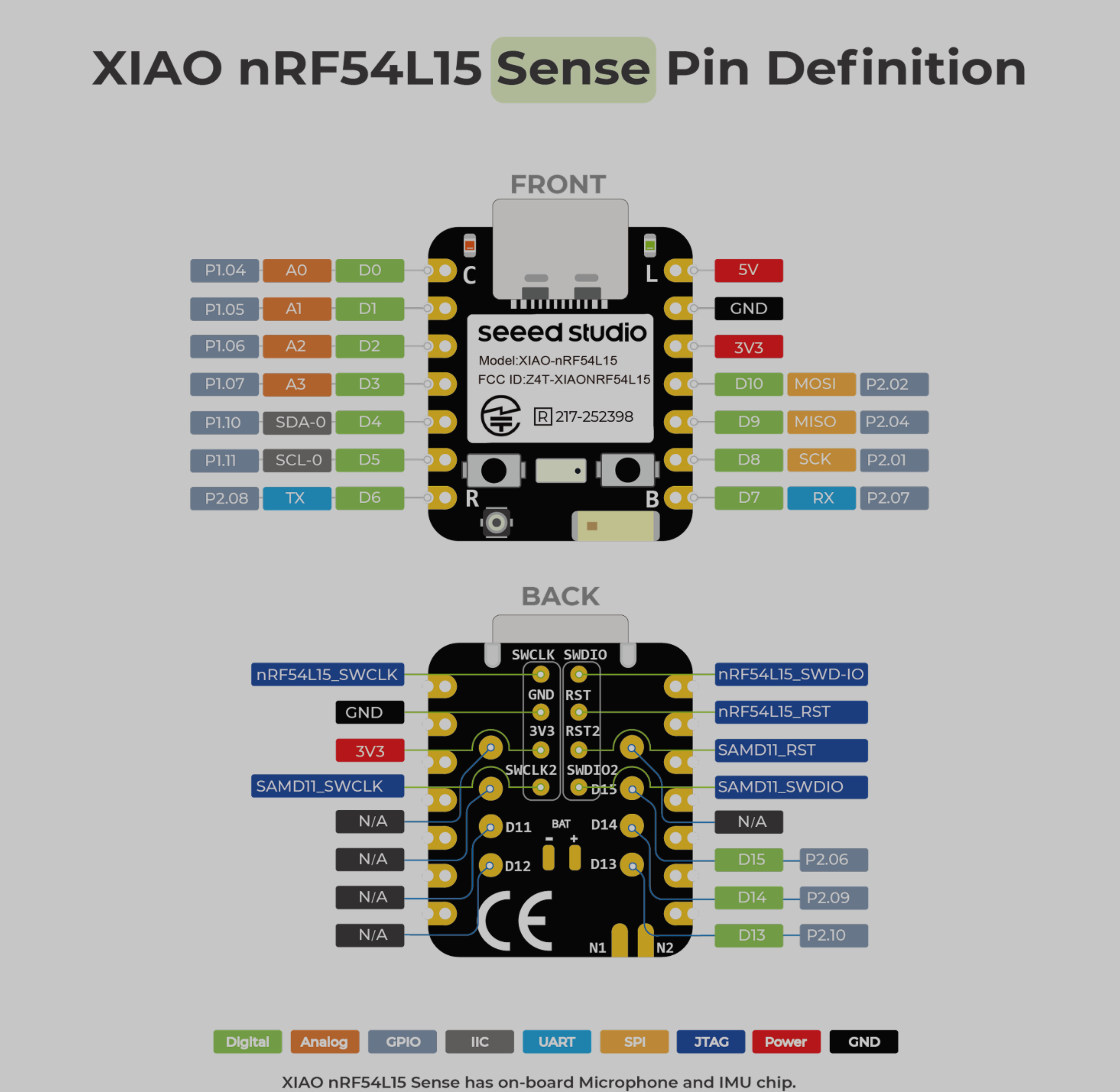 |
Mapa de pines
| Pin XIAO | Función | Pin del chip | Descripción |
|---|---|---|---|
| 5V | VBUS | Entrada/Salida de alimentación | |
| GND | |||
| 3V3 | 3V3_OUT | Salida de alimentación | |
| D0 | Analógico | P1.04 | GPIO, ADC |
| D1 | Analógico | P1.05 | GPIO, ADC |
| D2 | Analógico | P1.06 | GPIO, ADC |
| D3 | Analógico | P1.07 | GPIO, ADC |
| D4 | SDA-0 | P1.10 | GPIO, datos I2C |
| D5 | SCL-0 | P1.11 | GPIO, reloj I2C |
| D6 | TX | P2.08 | GPIO, transmisión UART |
| D7 | RX | P2.07 | GPIO, recepción UART |
| D8 | SPI_SCK | P2.01 | GPIO, reloj SPI |
| D9 | SPI_MISO | P2.04 | GPIO, datos SPI |
| D10 | SPI_MOSI | P2.02 | GPIO, datos SPI |
| D11 | SCL-1 | P0.03 | GPIO, I2C |
| D12 | SDA-1 | P0.04 | GPIO,I2C |
| D13 | GPIO | P2.10 | GPIO |
| D14 | GPIO | P2.09 | GPIO |
| D15 | GPIO | P2.06 | GPIO |
| nRF54L15_SWCLK | SWDCLK | JTAG | |
| nRF54L15_SWD-IO | SWDIO | JTAG | |
| nRF54L15_RST | RST | JTAG | |
| SAMD11_SWCLK | PA30 | JTAG | |
| SAMD11_SWDIO | PA31 | JTAG | |
| SAMD11_RST | RST2 | JTAG | |
| NFC1 | P1.02 | NRF | |
| NFC2 | P1.03 | NRF | |
| Reset | nRF54_RESET | EN | |
| USER KEY | P0.00 | Tecla de usuario | |
| RF Switch Port Select | P2.05 | Cambiar antena integrada | |
| RF Switch Power | P2.03 | Alimentación | |
| AIN7_VBAT | P1.14 | Leer el valor de voltaje de la batería | |
| CHARGE_LED | charge_LED | CHG-LED_Red | |
| USER_LED | P2.00 | Luz de usuario |
Uso del nRFConnect SDK
El nRF Connect SDK (NCS) es un kit de desarrollo de software extensible y unificado de Nordic Semiconductor diseñado específicamente para crear aplicaciones inalámbricas de bajo consumo para dispositivos inalámbricos basados en las series Nordic nRF52, nRF53, nRF54, nRF70 y nRF91.
NCS proporciona un rico ecosistema de aplicaciones de ejemplo listas para usar, pilas de protocolos, bibliotecas y controladores de hardware diseñados para simplificar el proceso de desarrollo y acelerar el tiempo de comercialización. Su naturaleza modular y configurable ofrece a los desarrolladores la flexibilidad de crear software optimizado en tamaño para dispositivos con memoria limitada, así como una potente funcionalidad para aplicaciones más avanzadas y complejas. NCS es un proyecto de código abierto alojado en GitHub y ofrece un excelente soporte para entornos de desarrollo integrados como Visual Studio Code.
Uso de nRF Connect SDK en VSCode
Instalar previamente los conocimientos sobre nRF Connect SDK
Este documento detalla cómo instalar el entorno de desarrollo de nRF Connect SDK en un ordenador con Windows 11. A continuación se ofrece una visión general de las herramientas que deben instalarse
-
Instalar VS Studio Code
-
nRF Command Line Tools
-
nRF Connect for Desktop
-
Git
-
Ninja
ninja --version
- CMake
cmake --version
- Zephyr SDK
west --version
- nRF Connect SDK
- Plugin nRF Connect para VSCode
Si ya lo has preinstalado en tu ordenador, puedes comprobar el número de versión de tu herramienta siguiendo el siguiente comando
VScode configura la placa y construye el archivo de grabación
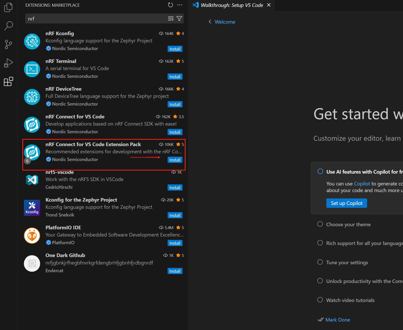
Abre VS Code y busca nRF Connect for VS Code Extension Pack en el Centro de Plugins. Este paquete de plugins instalará automáticamente otros plugins de VS Code necesarios para nRF Connect.
La extensión nRF Connect for VS Code permite a los desarrolladores utilizar el popular entorno de desarrollo integrado Visual Studio Code (VS Code IDE) para desarrollar, compilar, depurar y desplegar aplicaciones embebidas basadas en el nRF Connect SDK (Software Development Kit) de Nordic. La extensión incluye útiles herramientas de desarrollo como una interfaz de compilador, enlazador, sistema de compilación completo, depurador habilitado para RTOS, interfaz fluida con el nRF Connect SDK, editor de visualización de device tree y un terminal serie integrado.
El paquete de extensiones nRF Connect para VS Code incluye los siguientes componentes:
- nRF Connect for VS Code: La extensión principal contiene la interfaz entre el sistema de compilación y el nRF Connect SDK, así como una interfaz para gestionar la versión del nRF Connect SDK y la toolchain.
- nRF DeviceTree: Proporciona soporte para el lenguaje device tree y un editor de visualización de device tree.
- nRF Kconfig: Proporciona soporte para el lenguaje Kconfig.
- nRF Terminal: Terminales serie y RTT.
- Microsoft C/C++: Añade soporte de lenguaje para C/C++, incluyendo funciones de IntelliSense.
- CMake: Soporte para el lenguaje CMake.
- GNU Linker Mapping Files: Soporte para archivos de mapeo del enlazador. Podemos descargar cualquier versión preferida del nRF Connect SDK y su toolchain a través de la extensión. La documentación completa de nRF Connect para VS Code está disponible en https://docs.nordicsemi.com/bundle/nrf-connect-vscode/page/index.html.
Instalación de la toolchain
La toolchain es un conjunto de herramientas que trabajan juntas para compilar aplicaciones del nRF Connect SDK, incluyendo ensamblador, compilador, enlazador y componentes de CMake. La primera vez que abras nRF Connect para VS Code, se te pedirá que instales la toolchain. Esto suele ocurrir si la extensión no detecta ninguna toolchain instalada en tu ordenador. Haz clic en Install Toolchain y se mostrará una lista de versiones de toolchain que se pueden descargar e instalar en tu ordenador. Selecciona la versión de la toolchain que coincida con la versión del nRF Connect SDK que planeas utilizar. Siempre recomendamos utilizar la última versión etiquetada del nRF Connect SDK.
De forma predeterminada, nRF Connect para VS Code solo muestra la pestaña Released (es decir, la versión estable) de la toolchain. Si estás evaluando una nueva función y deseas utilizar la pestaña Preview u otro tipo de pestaña (por ejemplo, Customer Sampling -cs), haz clic en "Show all toolchain versions" como se muestra a continuación:
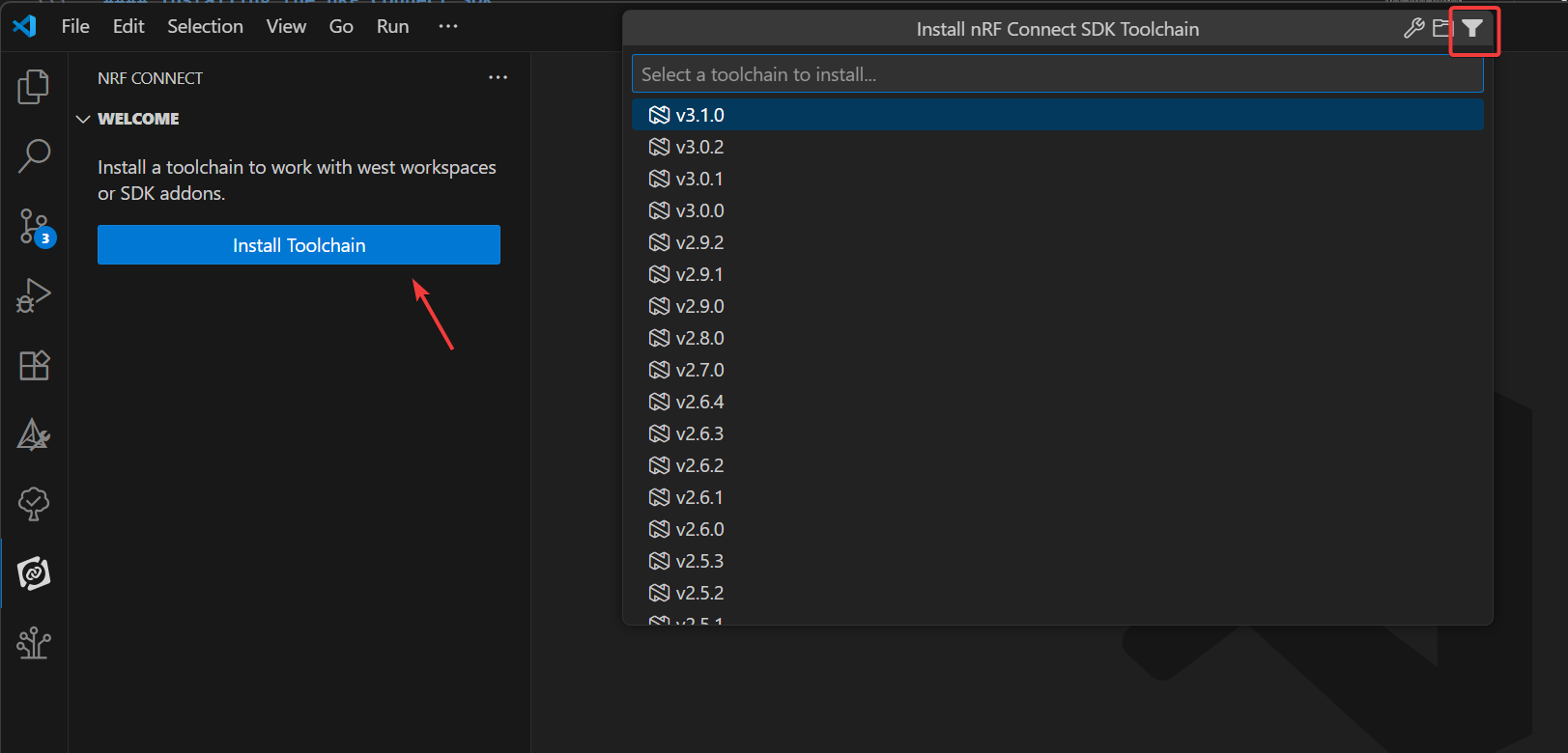
La ToolChain aquí es 3.0.1 o superior
Instalación del nRF Connect SDK
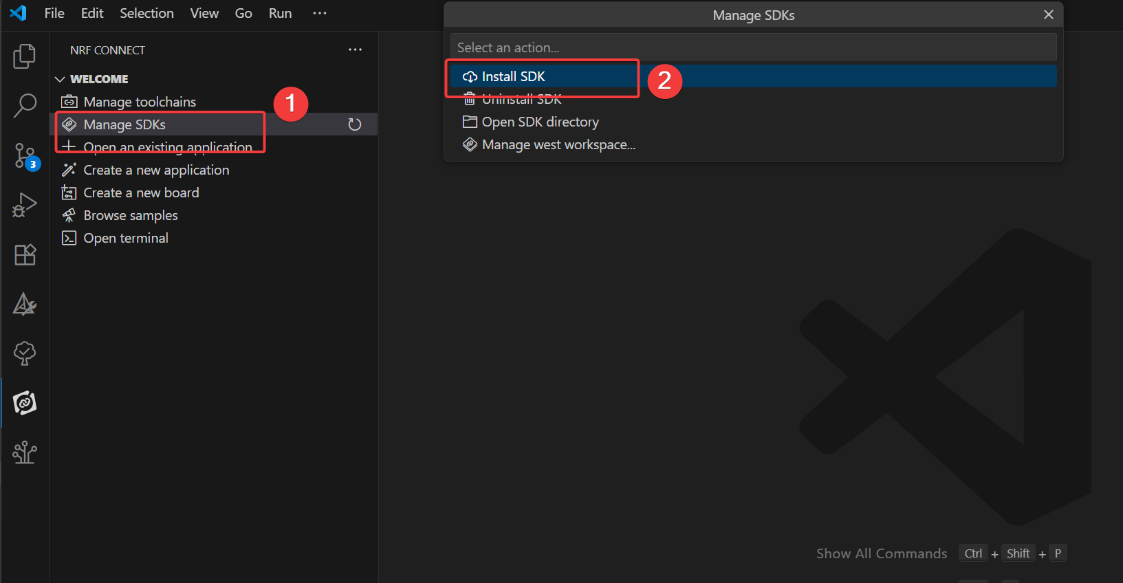
En la extensión nRF Connect para VS Code, haz clic en Manage SDK. Desde el menú Manage SDK, podemos instalar o desinstalar la versión de nRF Connect SDK. Dado que es la primera vez que utilizamos la extensión, la interfaz solo mostrará dos opciones.
Al hacer clic en Install SDK se enumerarán todas las versiones disponibles de nRF Connect SDK que se pueden descargar e instalar localmente. Selecciona la versión de nRF Connect SDK que se requiere para el desarrollo de tu proyecto.
Si has abierto la carpeta del SDK en VS Code, en lugar de la opción de menú Manage SDK, verás Manage west workspace. Para resolver este problema, abre otra ventana o carpeta en VS Code.
El nRF Connect SDK aquí es 3.0.1 o superior
Si no ves ninguna de estas opciones, asegúrate de tener instalada la última versión del paquete de extensiones nRF Connect para VS Code. Es importante tener en cuenta que el nRF Connect SDK es independiente del IDE, lo que significa que puedes elegir utilizar cualquier IDE o ninguno en absoluto. El nRF Connect SDK está disponible a través de la interfaz de línea de comandos https://www.nordicsemi.com/Products/Development-tools/nRF-Util (nrfutil). La interfaz de línea de comandos (CLI) (nrfutil) descargará e instalará nRF Connect. Sin embargo, recomendamos encarecidamente utilizar nuestra extensión nRF Connect para VS Code con VS Code, ya que integra no solo una cómoda interfaz gráfica de usuario (GUI) y una eficiente interfaz de línea de comandos (CLI), sino que también incluye una serie de funciones que simplificarán enormemente el desarrollo de firmware. Configurar otros IDE para que funcionen con el nRF Connect SDK requiere pasos manuales adicionales que van más allá del alcance de este curso.
Creación de programas de usuario
En este ejercicio escribiremos una aplicación sencilla basada en el ejemplo blinky para controlar el parpadeo de los LED en una placa de desarrollo. Lo mismo se aplica a todas las placas de desarrollo de Nordic Semiconductor compatibles (series nRF54, nRF53, nRF52, nRF70 o nRF91). El objetivo es asegurarse de que todas las herramientas necesarias para compilar y grabar el ejemplo estén configuradas correctamente. El enfoque está en aprender cómo crear una aplicación, compilarla y grabarla en una placa de desarrollo con chip Nordic utilizando la plantilla “Copy Example”.
- En VS Code, haz clic en el icono de la extensión nRF Connect. En la vista Welcome, haz clic en Create New Application.
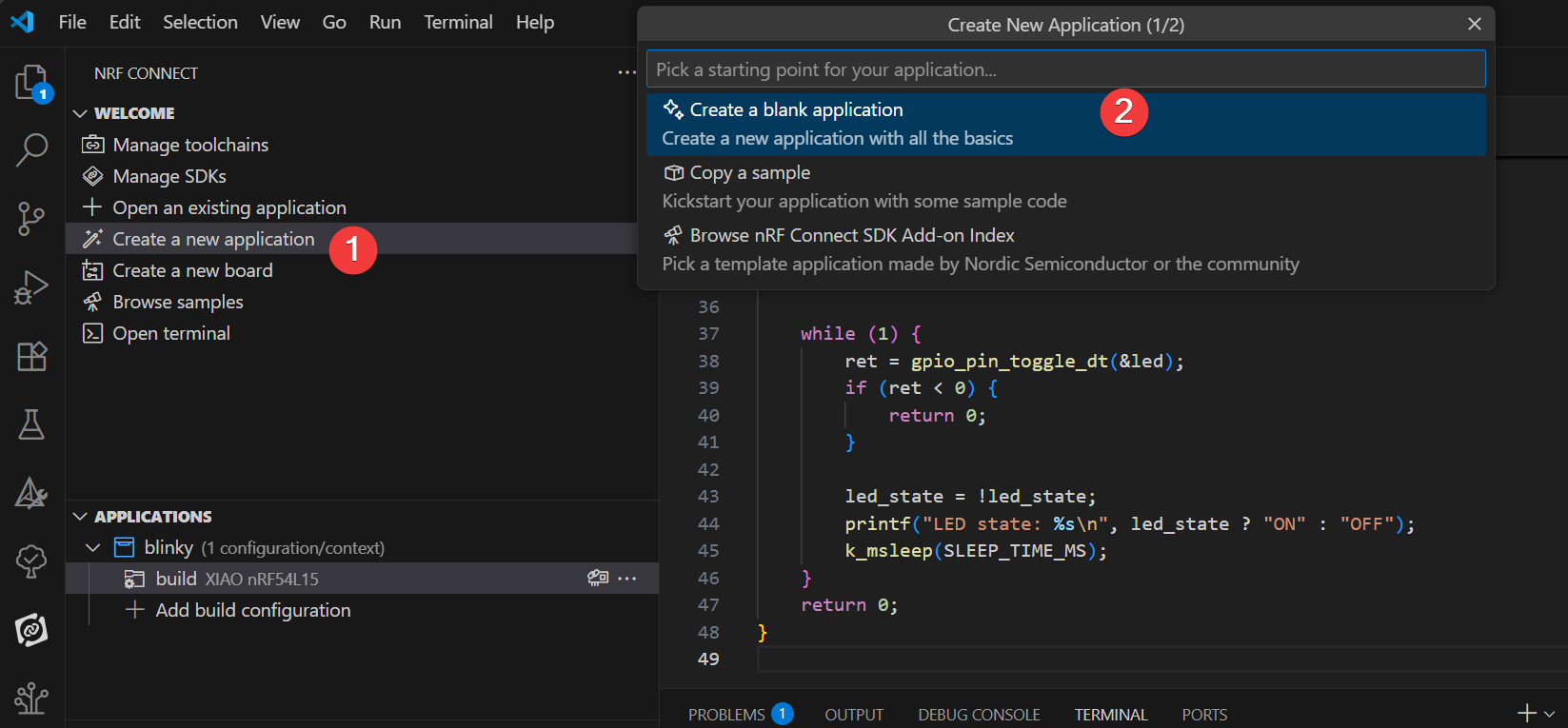
- Escribe blinky en la barra de búsqueda y selecciona el segundo ejemplo Blinky (ruta zephyr/samples/basic/blinky), como se muestra a continuación.
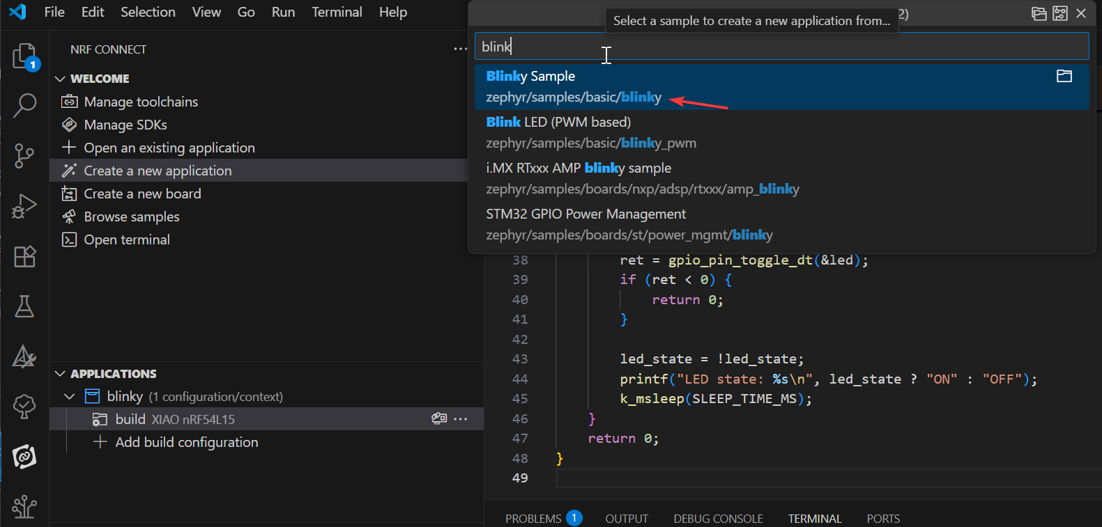
El ejemplo Blinky hará que el LED1 de la placa de desarrollo parpadee continuamente. Nuestra primera aplicación se basará en el ejemplo Blinky. El ejemplo Blinky se deriva del bloque de molde Zephyr en el nRF Connect SDK, por lo que verás el nombre zephyr en la ruta del ejemplo: zephyr\samples\basic\blinky.
Añadir la placa XIAO nRF54L15
Para comenzar, clona el repositorio desde el enlace de GitHubgit clone https://github.com/Seeed-Studio/platform-seeedboards.git en tu carpeta local preferida. Una vez clonado, navega al directorio platform-seeedboards/zephyr/. Recuerda esta ruta de la carpeta zephyr;
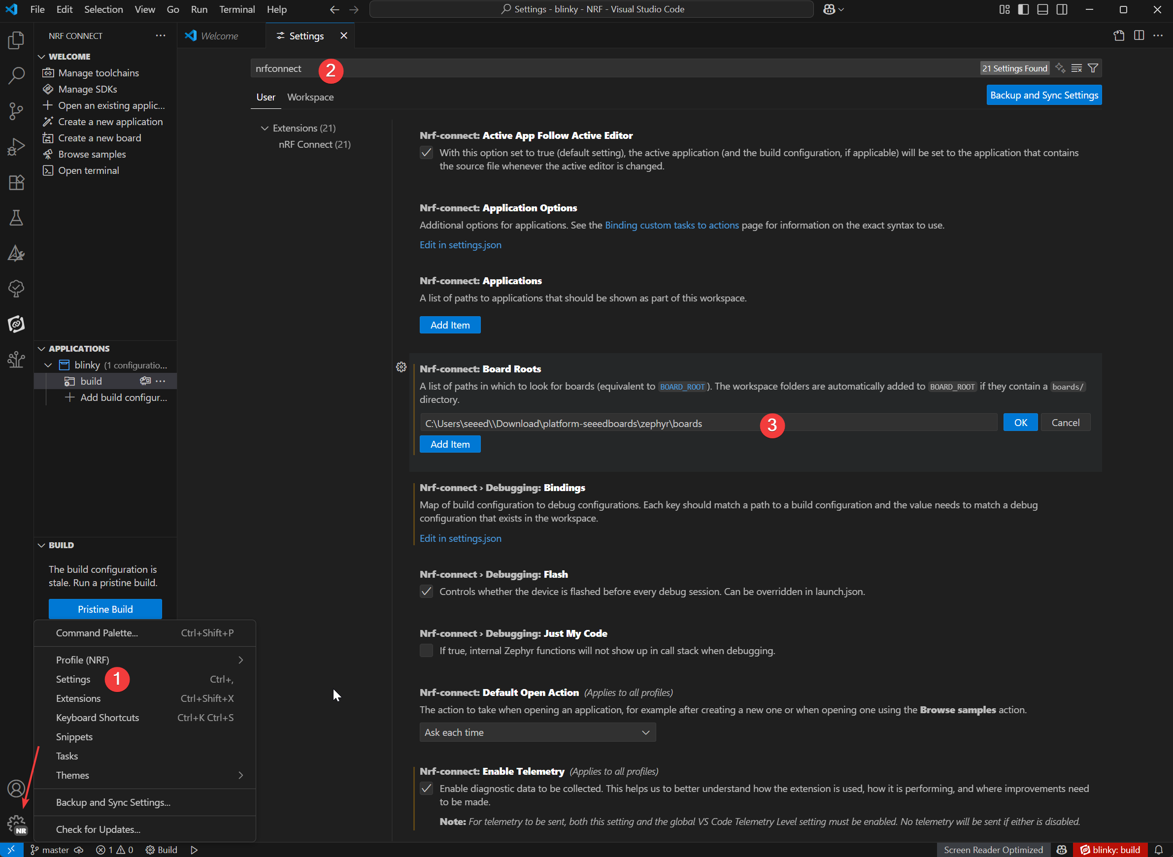
Para configurar tu placa para nRF Connect en VS Code, puedes seguir estos pasos:
-
Abre VS Code y ve a Settings.
-
Escribe nRF Connect en el cuadro de búsqueda.
-
Busca el elemento de configuración Board Roots y haz clic en Edit in settings.json.
-
Añade la ruta
zephyrdel archivo de la placa XIAO nRF54L15 descargado al array boardRoots.
-
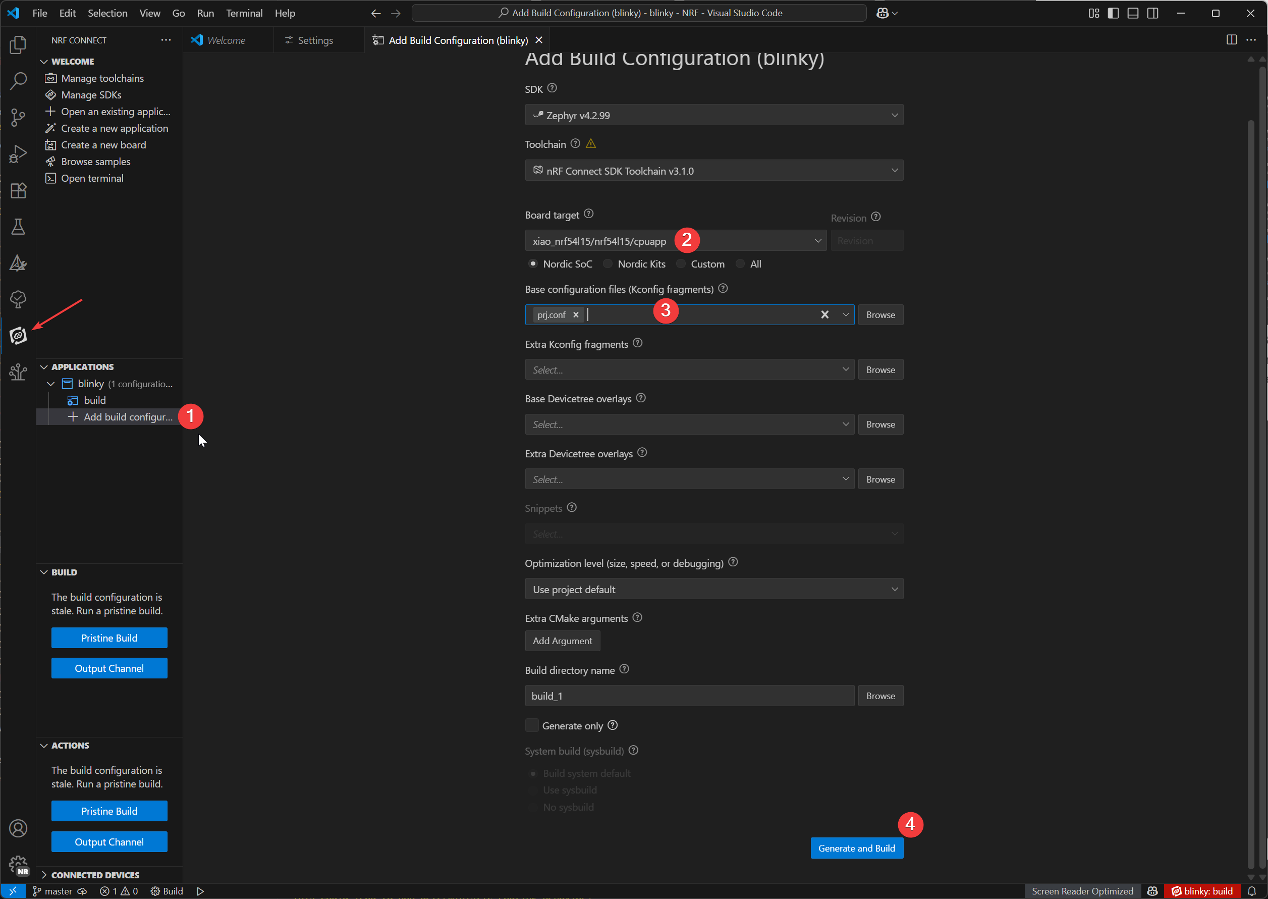
En la vista de la aplicación, haz clic en Add Build Configuration debajo del nombre de la aplicación.
-
Podemos seleccionar el modelo de XIAO nRF54L15 en Board target, y seleccionar el archivo prj.config predeterminado en Base configuration files, y finalmente hacer clic en
Generate and Buildpara compilar el archivo.
Descargar complemento de grabación
- Window
- Mac OS
Plugins adicionales:
En Windows, usaremos el gestor de paquetes Chocolatey para instalar OpenOCD.
1.Abre PowerShell (Ejecutar como administrador):
- En la barra de búsqueda de Windows, escribe "PowerShell".
- Haz clic derecho en "Windows PowerShell" y selecciona "Run as administrator".
2.Comprueba la directiva de ejecución de PowerShell:
- Escribe
Get-ExecutionPolicyy pulsa Enter. - Escribe
Get-ExecutionPolicy -Listy pulsa Enter.
3.Instala Chocolatey:
- Pega y ejecuta el siguiente comando:
Set-ExecutionPolicy Bypass -Scope Process -Force; [System.Net.ServicePointManager]::SecurityProtocol = [System.Net.ServicePointManager]::SecurityProtocol -bor 3072; iex ((New-Object System.Net.WebClient).DownloadString('https://community.chocolatey.org/install.ps1'))
Este comando omite la directiva de ejecución para la sesión actual de PowerShell e instala Chocolatey. Después de la instalación, cierra y vuelve a abrir la ventana de PowerShell (ejecutándola aún como administrador).
4.Instala OpenOCD:
- En la nueva ventana de PowerShell (como administrador), escribe:
choco install openocd
5.Verifica la instalación de OpenOCD:
-
Escribe
Get-Command openocdy pulsa Enter. -
Si la instalación es correcta, este comando mostrará la ruta a openocd.exe.
Plugins adicionales:
En macOS, usaremos el gestor de paquetes Homebrew para instalar las herramientas necesarias.
1.Instala Homebrew (si aún no está instalado):
-
Abre Terminal.app.
-
Ejecuta el siguiente comando:
/bin/bash -c "$(curl -fsSL https://raw.githubusercontent.com/Homebrew/install/HEAD/install.sh)"
- Sigue las indicaciones en pantalla; puede que necesites introducir la contraseña de usuario de macOS. Después de la instalación, ejecuta los comandos que indique la terminal para añadir Homebrew a tu variable de entorno PATH
(e.g., eval "$(/opt/homebrew/bin/brew shellenv)"). Luego cierra y vuelve a abrir la terminal.
2.Instala Ccache:
En la terminal, escribe:
brew install ccache
3.Instala OpenOCD:
En la terminal, escribe:
brew install openocd
4.Verifica la instalación de OpenOCD::
-
Escribe
which openocdy pulsa Enter. -
Si la instalación es correcta, este comando mostrará la ruta al ejecutable
openocd.
Programa de grabación West Flash
-
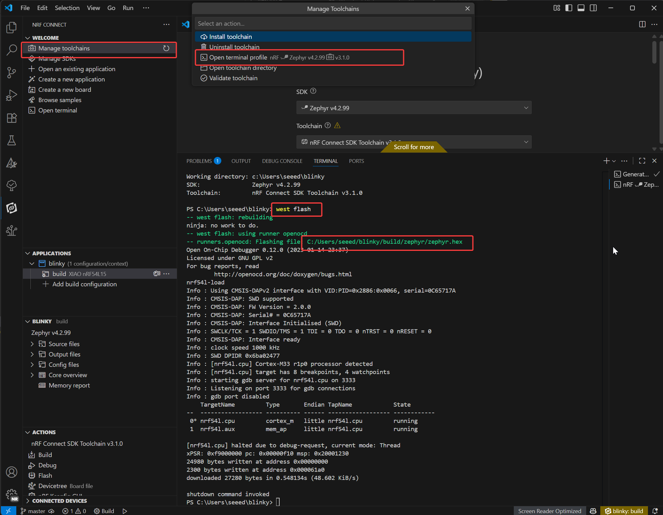
Abre la terminal de nRF
-
Solo introduce el comando
west flash, para grabar tu dispositivo, simplemente introduce el comando west flash. La ruta resaltada en rojo indica la ubicación de tu archivo .elf compilado. Puedes usar esta misma ruta para encontrar el archivo .hex correspondiente, que es adecuado para programar con un depurador J-Link.
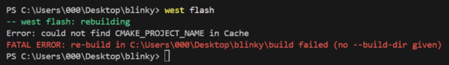
Si se produce un error de west flash, significa que hay un conflicto con el plugin CMake en VS Code, y necesitas eliminar el plugin CMake.
Cuando hayamos grabado correctamente el programa en la Seeed Studio XIAO nRF54L15 Sense, podrás ver en la placa, sobre el indicador de usuario, una luz verde parpadeando sin parar; si en tu caso también se ve el mismo efecto, ¡significa que lo has conseguido con éxito!🎊
Explicación del programa Blinky
/*
 * Copyright (c) 2016 Intel Corporation
 *
 * SPDX-License-Identifier: Apache-2.0
 */

#include <stdio.h>
#include <zephyr/kernel.h>
#include <zephyr/drivers/gpio.h>

/* 1000 msec = 1 sec */
#define SLEEP_TIME_MS   1000

/* The devicetree node identifier for the "led0" alias. */
#define LED0_NODE DT_ALIAS(led0)

/*
 * A build error on this line means your board is unsupported.
 * See the sample documentation for information on how to fix this.
 */
static const struct gpio_dt_spec led = GPIO_DT_SPEC_GET(LED0_NODE, gpios);

int main(void)
{
int ret;
bool led_state = true;

if (!gpio_is_ready_dt(&led)) {
  return 0;
}

ret = gpio_pin_configure_dt(&led, GPIO_OUTPUT_ACTIVE);
if (ret < 0) {
  return 0;
}

while (1) {
  ret = gpio_pin_toggle_dt(&led);
  if (ret < 0) {
    return 0;
  }

  led_state = !led_state;
  printf("LED state: %s\n", led_state ? "ON" : "OFF");
  k_msleep(SLEEP_TIME_MS);
}
return 0;
}
Definición del dispositivo LED:
#define LED0_NODE DT_ALIAS(led0): Recupera el identificador del nodo del device tree para el alias "led0", lo que permite una referencia al LED independiente del hardware.static const struct gpio_dt_spec led = GPIO_DT_SPEC_GET(LED0_NODE, gpios): Crea una estructura de especificación GPIO (led) usando el nodo del device tree, que contiene los detalles de hardware (pin, puerto) para el LED. Un error de compilación aquí indica hardware no compatible.
Inicialización de la función main():
-
Configuración de variables:
int ret: Almacena los valores de retorno de las funciones para comprobar el éxito de las operaciones.bool led_state = true: Rastrea el estado del LED (inicializado en "ON").
-
Comprobación de disponibilidad del GPIO:
if (!gpio_is_ready_dt(&led)) { return 0; }: Verifica si el hardware GPIO del LED está listo (por ejemplo, si el controlador está cargado). Sale si no está listo.
-
Configuración del GPIO:
ret = gpio_pin_configure_dt(&led, GPIO_OUTPUT_ACTIVE): Configura el pin GPIO del LED como salida activa en alto.- Sale en caso de fallo (
ret < 0) para evitar operaciones no válidas.
Bucle principal:
Se ejecuta en un bucle infinito while (1) para conmutar el LED periódicamente:
-
Conmutar el estado del LED:
ret = gpio_pin_toggle_dt(&led): Invierte la salida GPIO del LED (ON ↔ OFF). Sale en caso de fallo.
-
Actualizar el seguimiento del estado:
led_state = !led_state: Sincroniza el indicador de estado de software con el estado del hardware.
-
Registro y retardo:
printf("LED state: %s\n", led_state ? "ON" : "OFF"): Imprime el estado actual del LED a través de la salida serie.k_msleep(SLEEP_TIME_MS): Pausa durante 1000 ms (1 segundo) usando la función de retardo del RTOS de Zephyr, controlando la frecuencia de parpadeo.
Análisis profundo de los internos de nRF Connect SDK
Si quieres tener una comprensión más profunda de los principios internos de nRF Connect SDK, puedes consultar los siguientes cursos:
Restaurar la configuración de fábrica
Para las placas XIAO nRF54L15, se proporciona un script de restablecimiento de fábrica para recuperar la placa de un estado erróneo (por ejemplo, cuando no se puede cargar debido a la protección de escritura NVM interna). Este script realizará un borrado masivo de la flash y programará un firmware de fábrica.
Ubicación Los scripts se encuentran en el directorio scripts/factory_reset/. Uso El script creará y gestionará automáticamente un entorno virtual de Python local para instalar las herramientas necesarias, por lo que se puede ejecutar directamente.
Window
- Para Windows: Navega al directorio scripts/factory_reset y ejecuta:
.\factory_reset.bat
Linux-MacOS
- Para Linux y macOS: Navega al directorio scripts/factory_reset y ejecuta:
bash factory_reset.sh
Modo de conmutación inalámbrica
Este ejemplo demuestra cómo controlar el conmutador RF en la Seeed Studio XIAO nRF54L15 para alternar entre la antena integrada
::: El siguiente ejemplo funciona tanto para PlatformIO como para nRF Connect SDK. Se puede usar directamente en PlatformIO, mientras que el SDK requiere añadir archivos manualmente. Consulta este enlace :::
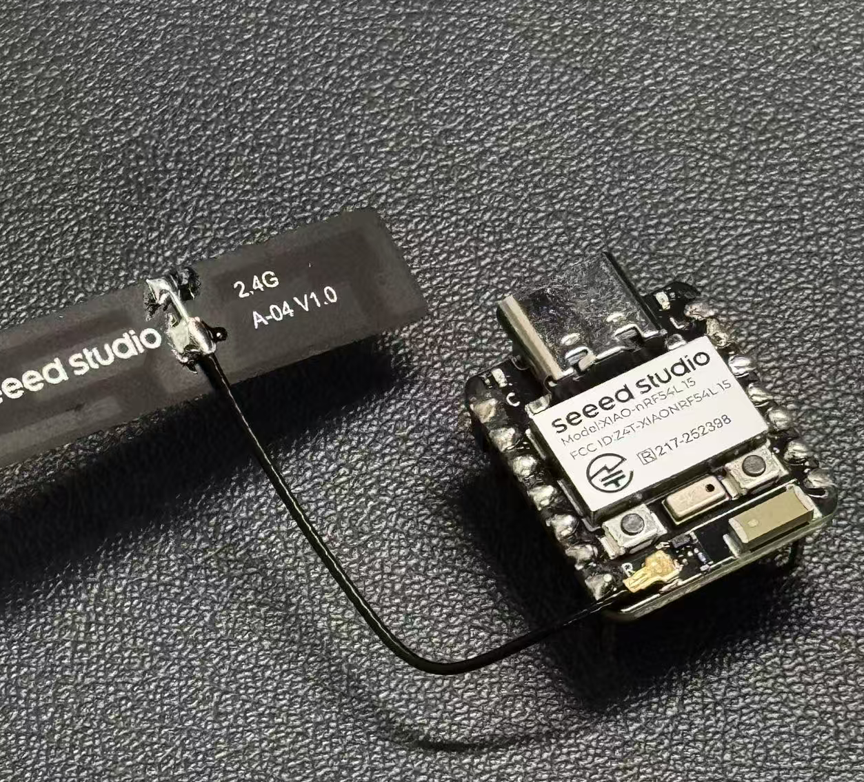
Antena externa
-
Antena cerámica y una antena externa.
-
Pulsa el botón de usuario (SW0) para cambiar entre las antenas cerámica y externa.
-
El LED de usuario indica la antena seleccionada actualmente (LED ENCENDIDO para la externa, LED APAGADO para la cerámica).
-
La antena predeterminada al inicio se puede configurar mediante prj.conf.
/*
 * Copyright (c) 2024 Seeed Technology Co.,Ltd
 *
 * SPDX-License-Identifier: Apache-2.0
 */

#include <zephyr/kernel.h>
#include <zephyr/device.h>
#include <zephyr/drivers/gpio.h>
#include <zephyr/logging/log.h>
#include <zephyr/devicetree.h>

LOG_MODULE_REGISTER(app, CONFIG_LOG_DEFAULT_LEVEL);

/* Devicetree node identifiers */
#define RFSW_REGULATOR_NODE DT_NODELABEL(rfsw_ctl)
#define SW0_NODE            DT_ALIAS(sw0)
#define LED0_NODE           DT_ALIAS(led0)

/* State variables */
static uint8_t onoff_flag = 0;
#ifdef CONFIG_DEFAULT_ANTENNA_EXTERNAL
static bool is_external_antenna = true;
#else
static bool is_external_antenna = false;
#endif

/* GPIO device specs */
/* Manually build gpio_dt_spec for rfsw_ctl */
static const struct gpio_dt_spec rfsw_gpio = {
	.port = DEVICE_DT_GET(DT_GPIO_CTLR(RFSW_REGULATOR_NODE, enable_gpios)),
	.pin = DT_GPIO_PIN(RFSW_REGULATOR_NODE, enable_gpios),
	.dt_flags = DT_GPIO_FLAGS(RFSW_REGULATOR_NODE, enable_gpios),
};
static const struct gpio_dt_spec button = GPIO_DT_SPEC_GET(SW0_NODE, gpios);
static const struct gpio_dt_spec led = GPIO_DT_SPEC_GET(LED0_NODE, gpios);

/* Button callback data */
static struct gpio_callback button_cb_data;

/* Forward declarations */
void button_pressed(const struct device *dev, struct gpio_callback *cb, uint32_t pins);
void update_antenna_switch(void);

/* Function to update antenna switch and LED */
void update_antenna_switch(void)
{
    int ret;
    is_external_antenna = !is_external_antenna;

    if (is_external_antenna) {
        /* Switch to external antenna */
        LOG_INF("Switching to External Antenna");

        // To get a physical high level (Inactive state), we need to set the logic to '0'
        ret = gpio_pin_set_dt(&rfsw_gpio, 0);
        if (ret < 0) {
            LOG_ERR("Error setting rfsw-ctl to physical HIGH: %d\n", ret);
        }

        // Turn on the LED (set 0 for on)
        ret = gpio_pin_set_dt(&led, 0);
        if (ret < 0) {
            LOG_ERR("Error turning on LED: %d\n", ret);
        }

    } else {
        /* Switch back to ceramic antenna */
        LOG_INF("Switching to Ceramic Antenna");

        // To get a physical low level (Active state), we need to set the logic to '1'
        ret = gpio_pin_set_dt(&rfsw_gpio, 1);
        if (ret < 0) {
            LOG_ERR("Error setting rfsw-ctl to physical LOW: %d\n", ret);
        }

        // Turn off the LED (set 1 for off)
        ret = gpio_pin_set_dt(&led, 1);
        if (ret < 0) {
            LOG_ERR("Error turning off LED: %d\n", ret);
        }
    }
}

/* Button pressed callback function */
void button_pressed(const struct device *dev, struct gpio_callback *cb,
                    uint32_t pins)
{
    update_antenna_switch();
}

int main(void)
{
    int ret;

    /* Check if GPIO devices are ready */
    if (!gpio_is_ready_dt(&rfsw_gpio)) {
        LOG_ERR("RF switch control GPIO not ready\n");
        return -1;
    }
    if (!gpio_is_ready_dt(&button)) {
        LOG_ERR("Button GPIO not ready\n");
        return -1;
    }
    if (!gpio_is_ready_dt(&led)) {
        LOG_ERR("LED GPIO not ready\n");
        return -1;
    }

    /* Configure GPIO pins */
    ret = gpio_pin_configure_dt(&rfsw_gpio, GPIO_OUTPUT);
    if (ret < 0) {
        LOG_ERR("Error configuring rfsw-ctl: %d\n", ret);
        return ret;
    }

    /* Configure LED as output, default off */
    ret = gpio_pin_configure_dt(&led, GPIO_OUTPUT_ACTIVE);
    if (ret < 0) {
        LOG_ERR("Error configuring LED: %d\n", ret);
        return ret;
    }

    /* Set initial LED state based on antenna selection */
    if (is_external_antenna) {
        // External antenna
        LOG_INF("Initial state: External Antenna");
        ret = gpio_pin_set_dt(&rfsw_gpio, 0);
        if (ret < 0) {
            LOG_ERR("Error setting rfsw-ctl to physical HIGH: %d\n", ret);
        }
        ret = gpio_pin_set_dt(&led, 0);  // Turn on LED
        if (ret < 0) {
            LOG_ERR("Error turning on LED: %d\n", ret);
        }
    } else {
        // Ceramic antenna
        LOG_INF("Initial state: Ceramic Antenna");
        ret = gpio_pin_set_dt(&rfsw_gpio, 1);
        if (ret < 0) {
            LOG_ERR("Error setting rfsw-ctl to physical LOW: %d\n", ret);
        }
        ret = gpio_pin_set_dt(&led, 1);  // Turn off LED
        if (ret < 0) {
            LOG_ERR("Error turning off LED: %d\n", ret);
        }
    }

    /* Configure button as input */
    ret = gpio_pin_configure_dt(&button, GPIO_INPUT);
    if (ret < 0) {
        LOG_ERR("Error configuring button: %d\n", ret);
        return ret;
    }

    /* Configure button interrupt */
    ret = gpio_pin_interrupt_configure_dt(&button, GPIO_INT_EDGE_TO_ACTIVE);
    if (ret < 0) {
        LOG_ERR("Error configuring button interrupt: %d\n", ret);
        return ret;
    }

    /* Initialize button callback */
    gpio_init_callback(&button_cb_data, button_pressed, BIT(button.pin));
    gpio_add_callback(button.port, &button_cb_data);

    LOG_INF("Antenna switch example started. Press SW0 to switch.\n");
    return 0;
}
Si deseas cambiar entre la antena externa o interna, necesitas modificar el archivo zephyr/prj.conf., Descomenta # CONFIG_DEFAULT_ANTENNA_EXTERNAL=y para habilitar la antena externa. Si utilizas la antena interna, comenta la línea.
CONFIG_GPIO=y
CONFIG_SERIAL=y
CONFIG_LOG=y
CONFIG_CONSOLE=y
CONFIG_UART_CONSOLE=y
CONFIG_SHELL_BACKEND_SERIAL=y
CONFIG_SHELL_BACKEND_DUMMY=n
CONFIG_PM_DEVICE=y
CONFIG_NRFX_POWER=y
CONFIG_POWEROFF=y

CONFIG_BT=y
CONFIG_BT_PERIPHERAL=y
CONFIG_BT_DEVICE_NAME="zephyr-ble"

# Enable this option to default to external antenna
# CONFIG_DEFAULT_ANTENNA_EXTERNAL=y
Acceder a los pines J-Link para grabar un programa
Si quieres usar JLink para programar, puedes seguir los pasos a continuación. Sin embargo, te sugerimos que utilices el puerto serie incorporado en la placa Seeed Stduio XIAO nRF54L15 para programar, lo cual será mucho más conveniente.
Hardware requerido
Necesitas descargar la última versión de J-Link para tener compatibilidad con la placa modelo nRF54L15.
Software requerido
Es necesario descargar el software Segger desde la página web.
- Paso 1. Usa Jlink para conectar los pines siguientes:
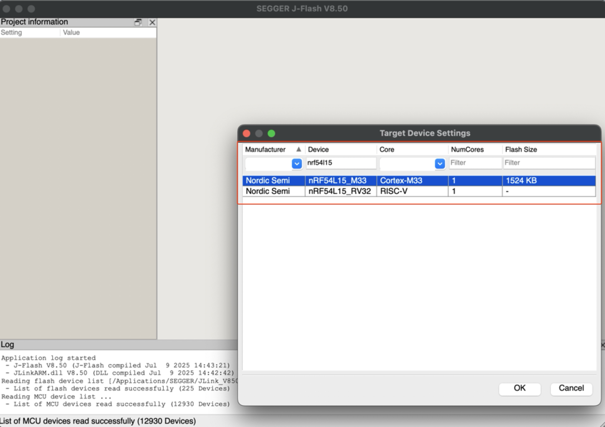
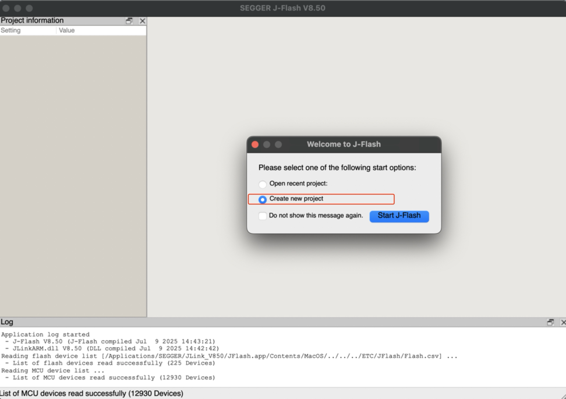
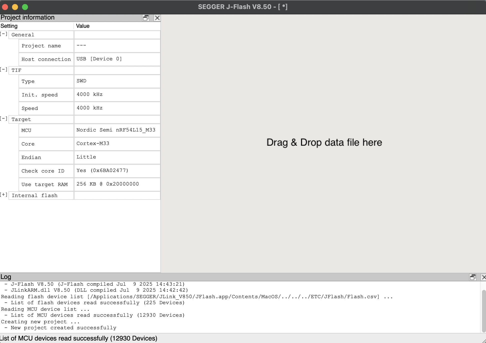
- Paso 2. Inicia J-Flash y busca nRF54L15_M33, creando un nuevo proyecto:
- Paso 3. Haz clic en "Target" y luego selecciona "Connect".
- Paso 4. Arrastra el archivo bin o archivo hex al software. Luego presiona F4 y F5 en ese orden. El reflash se habrá completado.
Placa alimentada por batería
La XIAO nRF54L15 tiene un chip de gestión de energía integrado que permite que la XIAO nRF54L15 se alimente de forma independiente usando una batería o que cargue la batería a través del puerto USB de la XIAO nRF54L15.
Si deseas conectar la batería para XIAO, te recomendamos comprar una batería de litio recargable de 3,7 V certificada. Al soldar la batería, ten cuidado de distinguir entre los terminales positivo y negativo.
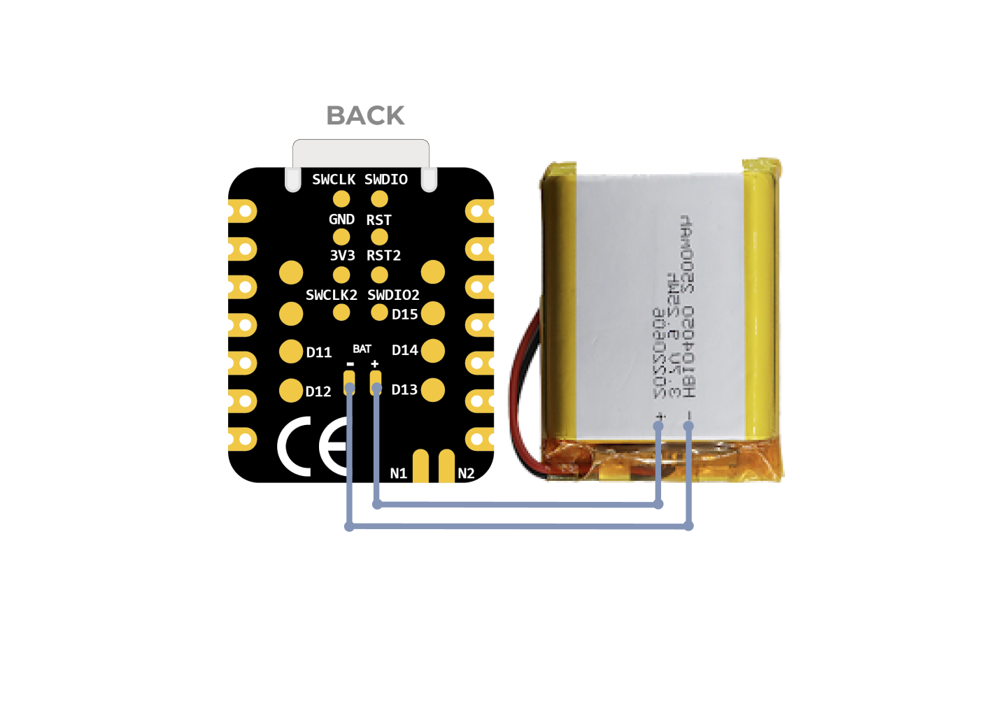
Esquema de conexión de la batería
Instrucciones sobre el uso de baterías:
- Utiliza baterías calificadas que cumplan con las especificaciones.
- XIAO puede conectarse a tu dispositivo informático mediante un cable de datos mientras usas la batería; ten la seguridad de que XIAO tiene un chip de protección de circuito integrado, lo cual es seguro.
- El XIAO nRF54L15 no tendrá ningún LED encendido cuando funcione con batería (a menos que hayas escrito un programa específico), por favor no juzgues si el XIAO nRF54L15 está funcionando o no por el estado del LED; evalúalo razonablemente según tu programa.
Al mismo tiempo, diseñamos una luz indicadora roja para la carga de la batería, que a través de la indicación luminosa informa al usuario del estado actual de la batería durante la carga.
Ten cuidado de no cortocircuitar los terminales positivo y negativo y quemar la batería y el equipo al soldar.
Detección de voltaje de la batería
Si te encuentras con una situación en la que el XIAO nRF54L15 no arranca cuando se alimenta únicamente con una batería de litio de 3,7 V después de grabar el programa, consulta las soluciones siguientes.
Para la versión de hardware actual (v1.0), recomendamos gestionar dos configuraciones de compilación para cambiar fácilmente entre Depuración en banco (USB conectado, UART habilitado) y Despliegue con batería (autónomo, UART deshabilitado).
Escenario A: Depuración en banco por USB
Cuándo usarlo: Estás escribiendo código, grabando firmware y necesitas ver los registros a través del Puerto Serie USB.
Configuración (prj_uart.conf):
Crea un nuevo archivo llamado prj_uart.conf en el directorio de tu proyecto. Este archivo overlay volverá a habilitar temporalmente el UART para fines de depuración.
# Enable UART for USB debugging
CONFIG_SERIAL=y
CONFIG_UART_CONSOLE=y
# Optional: Keep RTT enabled as a secondary logging backend
CONFIG_USE_SEGGER_RTT=y
CONFIG_RTT_CONSOLE=y
CONFIG_LOG_BACKEND_RTT=y
CONFIG_LOG_BACKEND_UART=y
Cómo compilar: Añade el argumento de configuración overlay al compilar tu proyecto.
# Build with UART enabled for USB debugging
west build -p always -d build_uart -b xiao_nrf54l15/nrf54l15/cpuapp . -DOVERLAY_CONFIG="prj_uart.conf"
Escenario B: Despliegue con batería (predeterminado)
Cuándo usarlo: Has terminado la depuración y pretendes alimentar la placa únicamente a través de las almohadillas de la batería.
Configuración (prj.conf):
Modifica tu archivo principal prj.conf para deshabilitar UART de forma predeterminada. Esto garantiza que la placa pueda arrancar correctamente cuando se alimente con una batería.
# Disable UART to ensure successful boot on battery
CONFIG_SERIAL=n
CONFIG_UART_CONSOLE=n
# Use RTT for low-power logging (requires J-Link)
CONFIG_USE_SEGGER_RTT=y
CONFIG_RTT_CONSOLE=y
CONFIG_LOG=y
CONFIG_LOG_BACKEND_RTT=y
Cómo compilar: Compila normalmente sin el argumento overlay.
# Build default firmware (Battery Safe)
west build -p always -d build_batt -b xiao_nrf54l15/nrf54l15/cpuapp .
Resumen
- Conectado por USB Usa el overlay
prj_uart.confpara habilitar el Monitor Serie. - Funcionando con batería Usa el
prj.confpredeterminado para garantizar que el dispositivo arranque sin problemas.
El XIAO nRF54L15 integra una función de detección de voltaje de batería que se centra en gestionar de forma eficiente las mediciones de potencia de la batería utilizando el interruptor de carga TPS22916CYFPR. Esta guía se centrará en analizar la implementación de software de la detección de batería (especialmente el código main.c) y te guiará sobre cómo desplegar y utilizar fácilmente esta función en un entorno PlatformIO, evitando la complejidad del SDK Zephyr NCS.
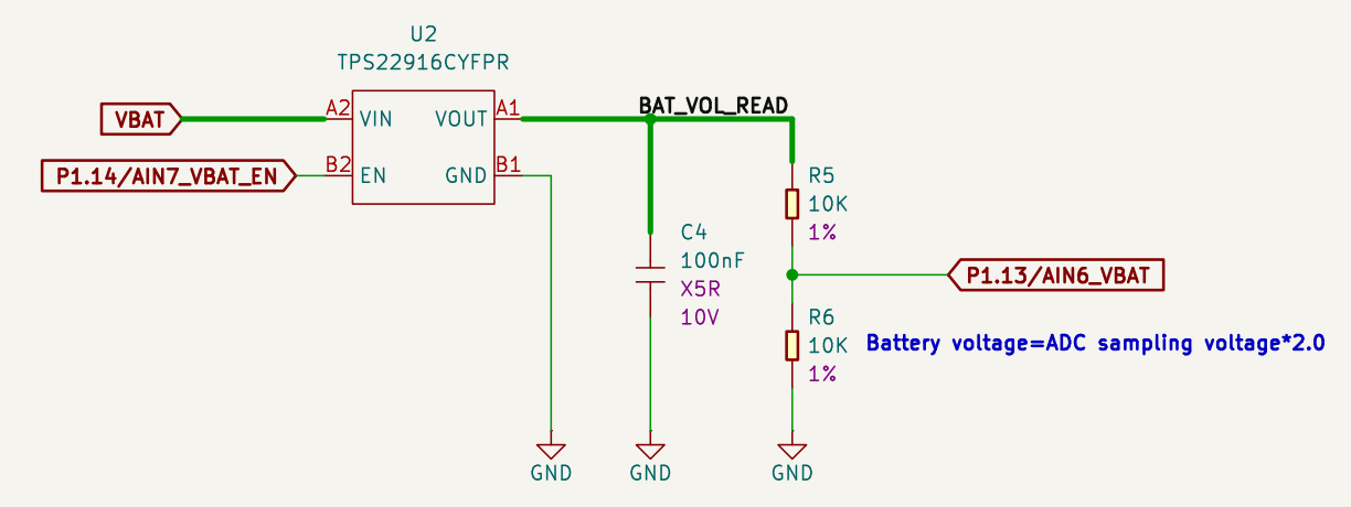
Esquema de detección de batería
Qué hace el chip TPS22916CYFPR:
-
Es un interruptor de alimentación inteligente que controla el encendido y apagado del voltaje de la batería según demanda. Cuando es necesario medir el voltaje de la batería, se encenderá, conectando la batería al circuito divisor de voltaje; cuando no sea necesario medirlo, se apagará, desconectando la conexión.
-
¿En qué nos ayuda esta función? A través de este mecanismo de conmutación bajo demanda, el chip reduce en gran medida el consumo de corriente innecesario y prolonga eficazmente la vida útil de la batería. Combinado con el posterior circuito divisor de voltaje y el ADC (convertidor analógico-digital) del nRF54L15, el XIAO nRF54L15 es capaz de monitorizar con precisión la carga restante de la batería, proporcionando una importante optimización de autonomía para aplicaciones de baja potencia alimentadas por batería, como los dispositivos IoT.
El siguiente código de ejemplo está diseñado para PlatformIO, pero también es compatible con el nRF Connect SDK.
Uso de XIAO nRF54L15 en PlatformIO Si quieres usar XIAO nRF54L15 en PlatformIO, consulta este tutorial para configurarlo: XIAO nRF54L15 PlatformIO Configuration.
Añadir overlay y modificar el archivo conf
Si quieres usar esta rutina de batería en el nRF Connect SDK, necesitas añadir app.overlay y modificar el archivo prj.conf.
-
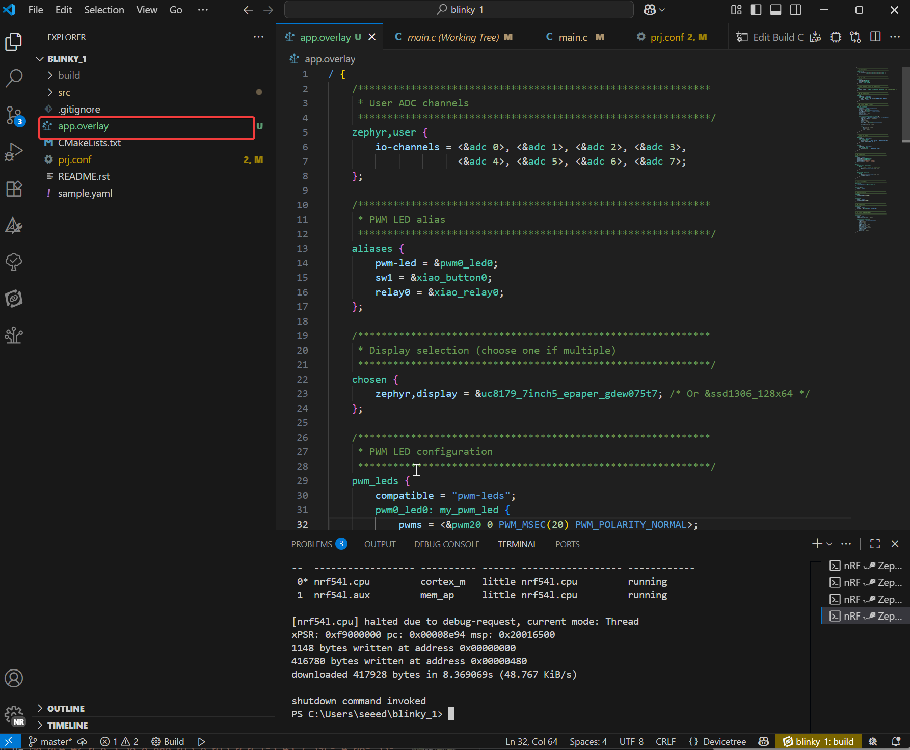
Crea un nuevo archivo llamado
app.overlayen el directorio del proyecto. Luego pega en él el siguiente código y, por último, pulsa Ctrl + S para guardar.- El archivo overlay amplía la capa de descripción de hardware y personaliza las conexiones físicas de hardware a través del árbol de dispositivos. No modifica la lógica del código, sino que declara los detalles reales del hardware para garantizar que el controlador pueda inicializar correctamente el dispositivo físico.
código de app.overlay
/ {
/*
  * @brief Device Tree Overlay for XIAO nRF54L15
  *
  * This file customizes the base board device tree to configure
  * peripherals for a specific application, including:
  * - User-defined ADC channels
  * - PWM-controlled LED
  * - Buttons and a relay
  * - E-paper display (UC8179) via SPI
  * - OLED display (SSD1306) via I2C
  *
  * To switch between the two displays, simply uncomment one and comment
  * out the other in the "chosen" node below.
  */

/************************************************************
  * Aliases for easy access to devices in application code
  ************************************************************/
aliases {
  pwm-led = &pwm0_led0;
  sw1 = &xiao_button0;
  relay0 = &xiao_relay0;
};

/************************************************************
  * Display selection (choose one if multiple)
  ************************************************************/
chosen {
  zephyr,display = &uc8179_7inch5_epaper_gdew075t7;
  zephyr,display = &ssd1306_128x64;
};

/************************************************************
  * PWM LED, Button, and Relay configuration
  ************************************************************/
pwm_leds {
  compatible = "pwm-leds";
  pwm0_led0: my_pwm_led {
    // PWM channel 0 on PWM instance 20
    // PWM_MSEC(20) sets a period of 20ms
    pwms = <&pwm20 0 PWM_MSEC(20) PWM_POLARITY_NORMAL>;
    status = "okay";
  };
};

buttons {
  compatible = "gpio-keys";
  xiao_button0: button_0 {
    // Connect to the XIAO nRF54L15 pin D1
    // GPIO_PULL_UP ensures the pin is high when the button is not pressed
    // GPIO_ACTIVE_LOW means the button press drives the pin low
    gpios = <&xiao_d 1 (GPIO_PULL_UP | GPIO_ACTIVE_LOW)>;
    zephyr,code = <INPUT_KEY_0>;
  };
};

relay {
  compatible = "gpio-leds";
  xiao_relay0: relay_0 {
    // Connect to the XIAO nRF54L15 pin D0
    gpios = <&xiao_d 0 GPIO_ACTIVE_HIGH>;
  };
};

/************************************************************
  * Local nodes that don't modify existing ones
  ************************************************************/
zephyr,user {
  io-channels = <&adc 0>, <&adc 1>, <&adc 2>, <&adc 3>,
          <&adc 4>, <&adc 5>, <&adc 6>, <&adc 7>;
};

// MIPI-DBI SPI interface for the E-paper display
mipi_dbi_xiao_epaper {
  compatible = "zephyr,mipi-dbi-spi";
  spi-dev = <&xiao_spi>;
  // D3 pin for Data/Command control
  dc-gpios = <&xiao_d 3 GPIO_ACTIVE_HIGH>;
  // D0 pin for Reset
  reset-gpios = <&xiao_d 0 GPIO_ACTIVE_LOW>;
  write-only;
  #address-cells = <1>;
  #size-cells = <0>;

  uc8179_7inch5_epaper_gdew075t7: uc8179@0 {
    compatible = "gooddisplay,gdew075t7", "ultrachip,uc8179";
    // Max SPI frequency for the display
    mipi-max-frequency = <4000000>;
    reg = <0>;
    width = <800>;
    height = <480>;
    // D2 pin for Busy signal from the display
    busy-gpios = <&xiao_d 2 GPIO_ACTIVE_LOW>;
    softstart = [17 17 17 17];
    full {
      pwr = [07 07 3f 3f];
      cdi = <07>;
      tcon = <0x22>;
    };
  };
};
};

/************************************************************
* Device fragments (modifying nodes from the base board DTS)
************************************************************/
// PWM instance 20
&pwm20 {
status = "okay";
pinctrl-0 = <&pwm20_default>;
pinctrl-1 = <&pwm20_sleep>;
pinctrl-names = "default", "sleep";
};

// GPIO pin control
&pinctrl {
pwm20_default: pwm20_default {
  group1 {
    // Configure PWM channel 0 on P1.04 pin (Pin D0)
    psels = <NRF_PSEL(PWM_OUT0, 1, 4)>;
  };
};

pwm20_sleep: pwm20_sleep {
  group1 {
    psels = <NRF_PSEL(PWM_OUT0, 1, 4)>;
    low-power-enable;
  };
};
};

// PDM instance 20 for DMIC
dmic_dev: &pdm20 {
status = "okay";
};

// Power configuration
&pdm_imu_pwr {
/delete-property/ regulator-boot-on;
};

// UART instance 20
&uart20 {
current-speed = <921600>;
};

// SPI peripheral
&xiao_spi {
status = "okay";
// D1 pin for Chip Select
cs-gpios = <&xiao_d 1 GPIO_ACTIVE_LOW>;
};

// I2C peripheral
&xiao_i2c {
status = "okay";
zephyr,concat-buf-size = <2048>;

ssd1306_128x64: ssd1306@3c {
  compatible = "solomon,ssd1306fb";
  reg = <0x3c>;
  width = <128>;
  height = <64>;
  segment-offset = <0>;
  page-offset = <0>;
  display-offset = <0>;
  multiplex-ratio = <63>;
  segment-remap;
  com-invdir;
  prechargep = <0x22>;
};
};
-
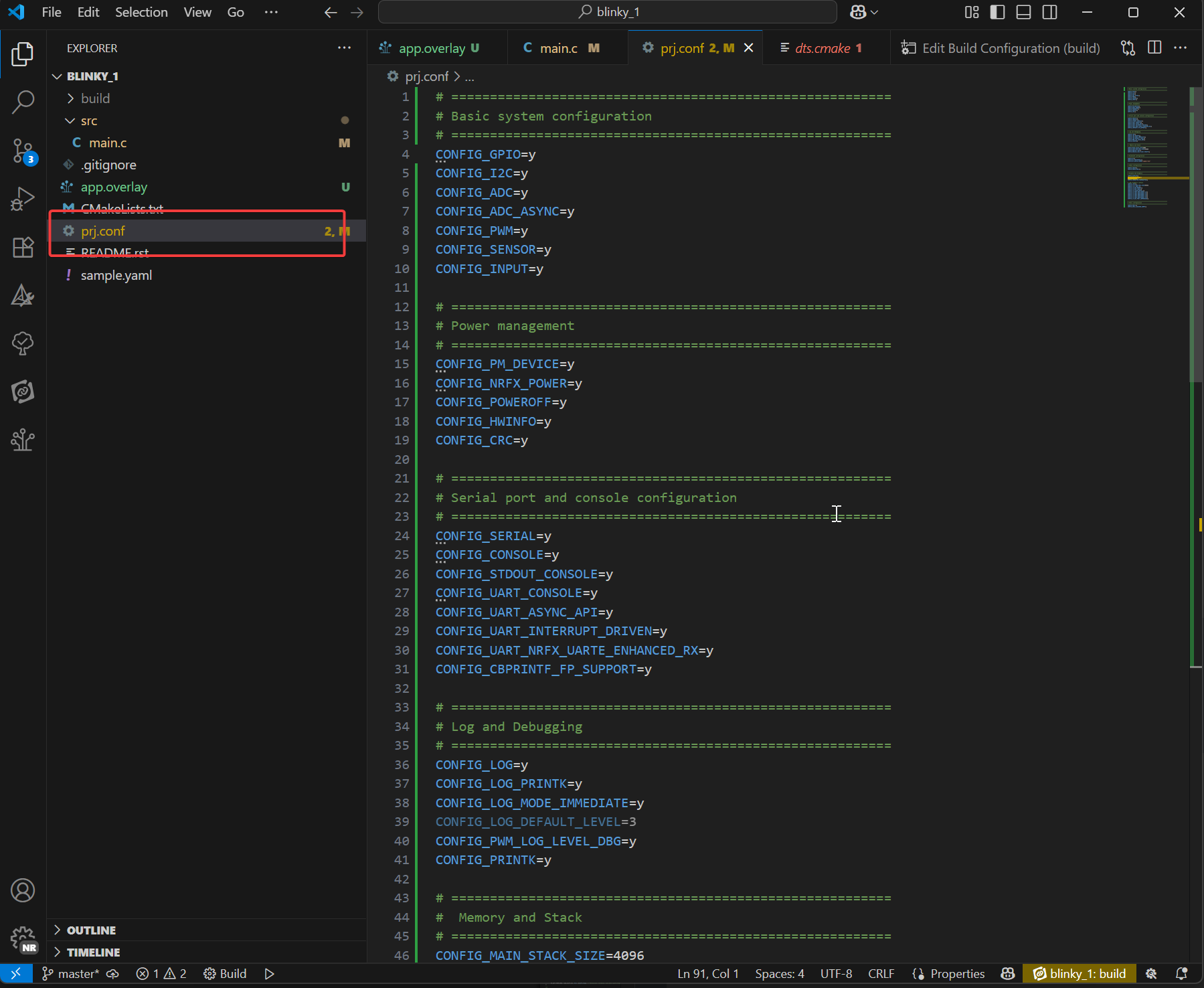
Añade el siguiente contenido en el archivo prj.conf
- prj.conf es el archivo de configuración principal del proyecto Zephyr. Está gestionado por el sistema Kconfig para la selección de funciones de software durante la compilación. Determina qué controladores (como ADC, pantalla, Bluetooth), middleware (como LVGL) y servicios del sistema (como registro, gestión de memoria) se incluyen en el firmware, y establece sus parámetros de comportamiento (como nivel de registro, tamaño del montón). Finalmente, pulsa Ctrl + S para guardar.
código de prj.conf
# =========================================================
# Basic system configuration
# =========================================================
CONFIG_GPIO=y
CONFIG_I2C=y
CONFIG_ADC=y
CONFIG_ADC_ASYNC=y
CONFIG_PWM=y
CONFIG_SENSOR=y
CONFIG_INPUT=y

# =========================================================
# Power management
# =========================================================
CONFIG_PM_DEVICE=y
CONFIG_NRFX_POWER=y
CONFIG_POWEROFF=y
CONFIG_HWINFO=y
CONFIG_CRC=y

# =========================================================
# Serial port and console configuration
# =========================================================
CONFIG_SERIAL=y
CONFIG_CONSOLE=y
CONFIG_STDOUT_CONSOLE=y
CONFIG_UART_CONSOLE=y
CONFIG_UART_ASYNC_API=y
CONFIG_UART_INTERRUPT_DRIVEN=y
CONFIG_UART_NRFX_UARTE_ENHANCED_RX=y
CONFIG_CBPRINTF_FP_SUPPORT=y

# =========================================================
# Log and Debugging
# =========================================================
CONFIG_LOG=y
CONFIG_LOG_PRINTK=y
CONFIG_LOG_MODE_IMMEDIATE=y
CONFIG_LOG_DEFAULT_LEVEL=3
CONFIG_PWM_LOG_LEVEL_DBG=y
CONFIG_PRINTK=y

# =========================================================
#  Memory and Stack
# =========================================================
CONFIG_MAIN_STACK_SIZE=4096
CONFIG_HEAP_MEM_POOL_SIZE=16384
CONFIG_NEWLIB_LIBC=y
CONFIG_NEWLIB_LIBC_FLOAT_PRINTF=y

# =========================================================
# Bluetooth configuration
# =========================================================
CONFIG_BT=y
CONFIG_BT_PERIPHERAL=y
CONFIG_BT_DEVICE_NAME="zephyr-ble"

# =========================================================
# Audio configuration
# =========================================================
CONFIG_AUDIO=y
CONFIG_AUDIO_DMIC=y

# =========================================================
# Display and Graphics
# =========================================================
CONFIG_DISPLAY=y
CONFIG_MIPI_DBI_SPI=y
CONFIG_SSD1306=y
CONFIG_CHARACTER_FRAMEBUFFER=y

# LVGL Graphics Library
CONFIG_LVGL=y
CONFIG_LV_Z_MEM_POOL_SIZE=49152
CONFIG_LV_Z_SHELL=y
CONFIG_LV_USE_MONKEY=y
CONFIG_LV_USE_LABEL=y
CONFIG_LV_COLOR_DEPTH_1=y
CONFIG_LV_FONT_MONTSERRAT_12=y
CONFIG_LV_FONT_MONTSERRAT_14=y
CONFIG_LV_FONT_MONTSERRAT_16=y
CONFIG_LV_FONT_MONTSERRAT_18=y
CONFIG_LV_FONT_MONTSERRAT_24=y
CONFIG_LV_USE_FONT_COMPRESSED=y

# =========================================================
# Shell configuration
# =========================================================
CONFIG_SHELL=y
CONFIG_SHELL_BACKEND_DUMMY=y
Código principal
#include <inttypes.h>
#include <stddef.h>
#include <stdint.h>
#include <zephyr/device.h>
#include <zephyr/devicetree.h>
#include <zephyr/drivers/regulator.h>
#include <zephyr/drivers/adc.h>
#include <zephyr/kernel.h>


#if !DT_NODE_EXISTS(DT_PATH(zephyr_user)) || \
 !DT_NODE_HAS_PROP(DT_PATH(zephyr_user), io_channels)
#error "No suitable devicetree overlay specified"
#endif

#define DT_SPEC_AND_COMMA(node_id, prop, idx) \
 ADC_DT_SPEC_GET_BY_IDX(node_id, idx),

/* Data of ADC io-channels specified in devicetree. */
static const struct adc_dt_spec adc_channels[] = {
 DT_FOREACH_PROP_ELEM(DT_PATH(zephyr_user), io_channels,
       DT_SPEC_AND_COMMA)};

static const struct device *const vbat_reg = DEVICE_DT_GET(DT_NODELABEL(vbat_pwr));

int main(void)
{
 int err;
 uint16_t buf;
 int32_t val_mv;
 struct adc_sequence sequence = {
  .buffer = &buf,
  /* buffer size in bytes, not number of samples */
  .buffer_size = sizeof(buf),
 };

 regulator_enable(vbat_reg);
 k_sleep(K_MSEC(100));

 /* Configure channels individually prior to sampling. */
 if (!adc_is_ready_dt(&adc_channels[7]))
 {
  printf("ADC controller device %s not ready\n", adc_channels[7].dev->name);
  return 0;
 }

 err = adc_channel_setup_dt(&adc_channels[7]);
 if (err < 0)
 {
  printf("Could not setup channel #7 (%d)\n", err);
  return 0;
 }

 (void)adc_sequence_init_dt(&adc_channels[7], &sequence);

 err = adc_read_dt(&adc_channels[7], &sequence);
 if (err < 0)
 {
  printf("Could not read (%d)\n", err);
  return 0;
 }

 /*
  * If using differential mode, the 16 bit value
  * in the ADC sample buffer should be a signed 2's
  * complement value.
  */
 if (adc_channels[7].channel_cfg.differential)
 {
  val_mv = (int32_t)((int16_t)buf);
 }
 else
 {
  val_mv = (int32_t)buf;
 }
 err = adc_raw_to_millivolts_dt(&adc_channels[7],
           &val_mv);
 /* conversion to mV may not be supported, skip if not */
 if (err < 0)
 {
  printf(" value in mV not available\n");
 }
 else
 {
  printf("bat vol = %" PRId32 " mV\n", val_mv * 2);
 }

 regulator_disable(vbat_reg);
 return 0;
}
Recursos
Seeed Studio XIAO nRF54L15
Diseño de hardware
- 📄[Hoja de datos] Nordic nRF54L15 Datasheet
- 📄[Esquemático] XIAO nRF54L15 Schematic
- 🗃️[Archivos de diseño de PCB] XIAO nRF54L15 KiCad Project
- 🗃️[Bibliotecas de diseño de PCB]
- 📄[Diagrama de pines] XIAO nRF54L15 Pinout Sheet
Mecánico
- 🗃️[Dimensiones 2D] XIAO nRF54L15 Dimension in DXF
Seeed Studio XIAO nRF54L15 Sense
Diseño de hardware
- 📄[Hoja de datos] Nordic nRF54L15 Datasheet
- 📄[Esquemático] XIAO nRF54L15 Sense Schematic
- 🗃️[Archivos de diseño de PCB]
- 🗃️[Bibliotecas de diseño de PCB]
- 🗃️[Diagrama de pines] XIAO nRF54L15 Sense Pinout Sheet
Mecánico
- 📄[Dimensiones 2D] XIAO nRF54L15 Sense Dimension in DXF
- 🗃️[Dimensiones 3D] XIAO nRF54L15 Sense 3D imensions
Soporte técnico y debate sobre el producto
Gracias por elegir nuestros productos. Estamos aquí para ofrecerte diferentes tipos de soporte y garantizar que tu experiencia con nuestros productos sea lo más fluida posible. Ofrecemos varios canales de comunicación para adaptarnos a distintas preferencias y necesidades.