Multiplexación de pines con Seeed Studio XIAO nRF54L15 Sense
Para facilitar su uso, todos los siguientes ejemplos de multiplexación de pines se realizan en PlatformIO. Haz clic en este enlace para ver una guía de configuración y uso para la XIAO nRF54L5
Basado en VS Code, si quieres usar el siguiente caso en el nRF Connect SDK, consulta la conexión proporcionada, añade el archivo app.overlay y modifica el contenido en prj.conf
XIAO nRF54L15 Añadir archivo overlay y modificar archivo conf.
Botones integrados
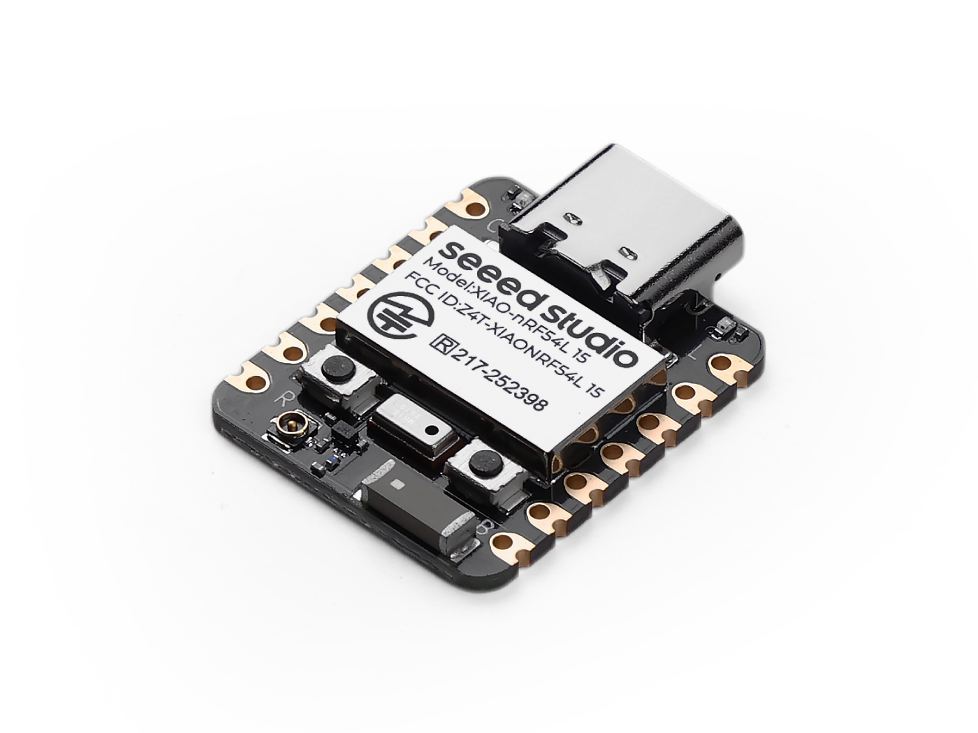
XIAO nRF54L15(Sense) viene equipado con dos botones físicos importantes que desempeñan funciones cruciales en el funcionamiento del dispositivo y la programación del firmware: el Botón de reinicio y el Botón de usuario. Comprender sus funciones es esencial para el uso diario y las actualizaciones de firmware.
Descripción general del hardware
- XIAO nRF54L15
- XIAO nRF54L15 Sense
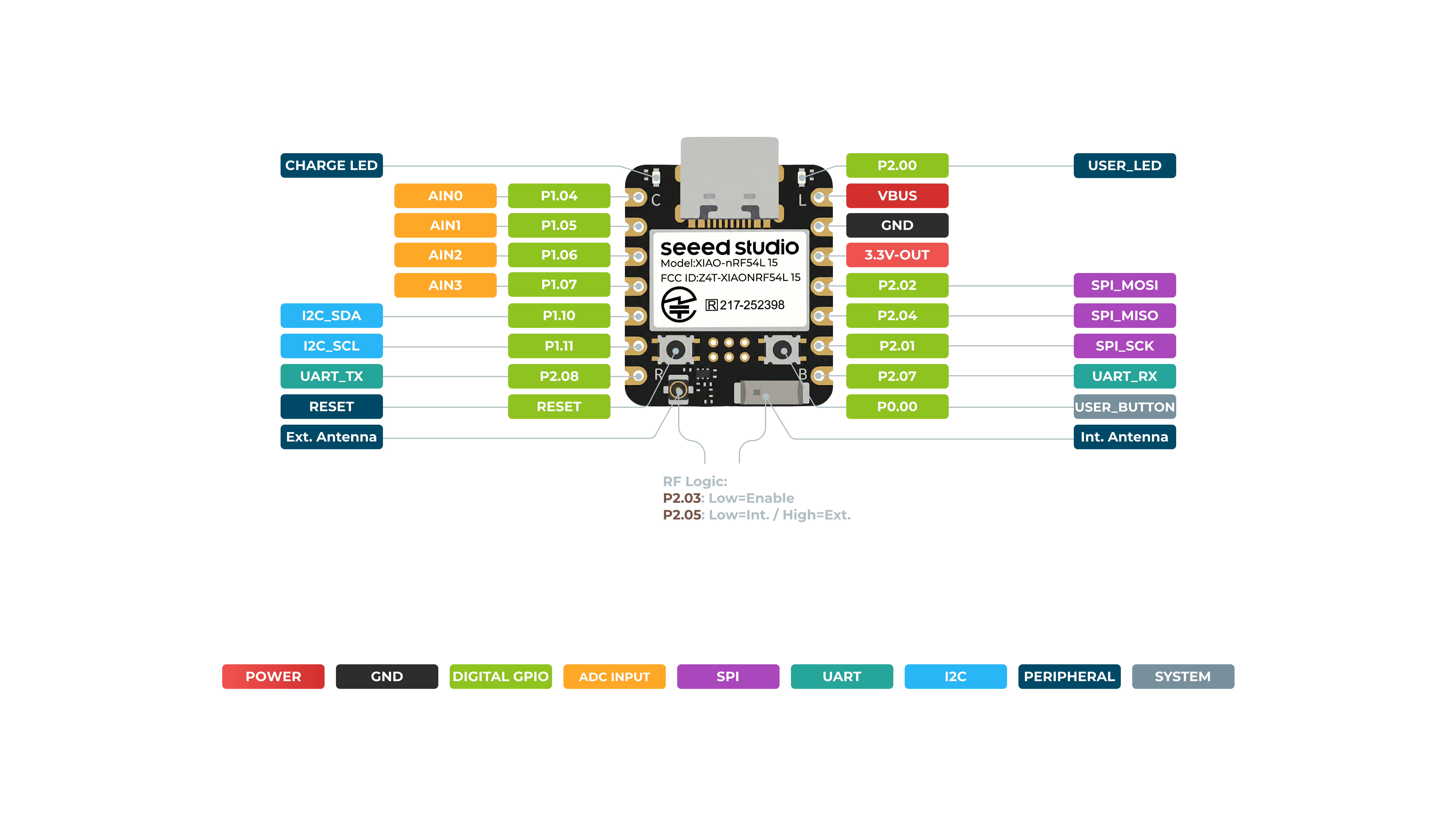
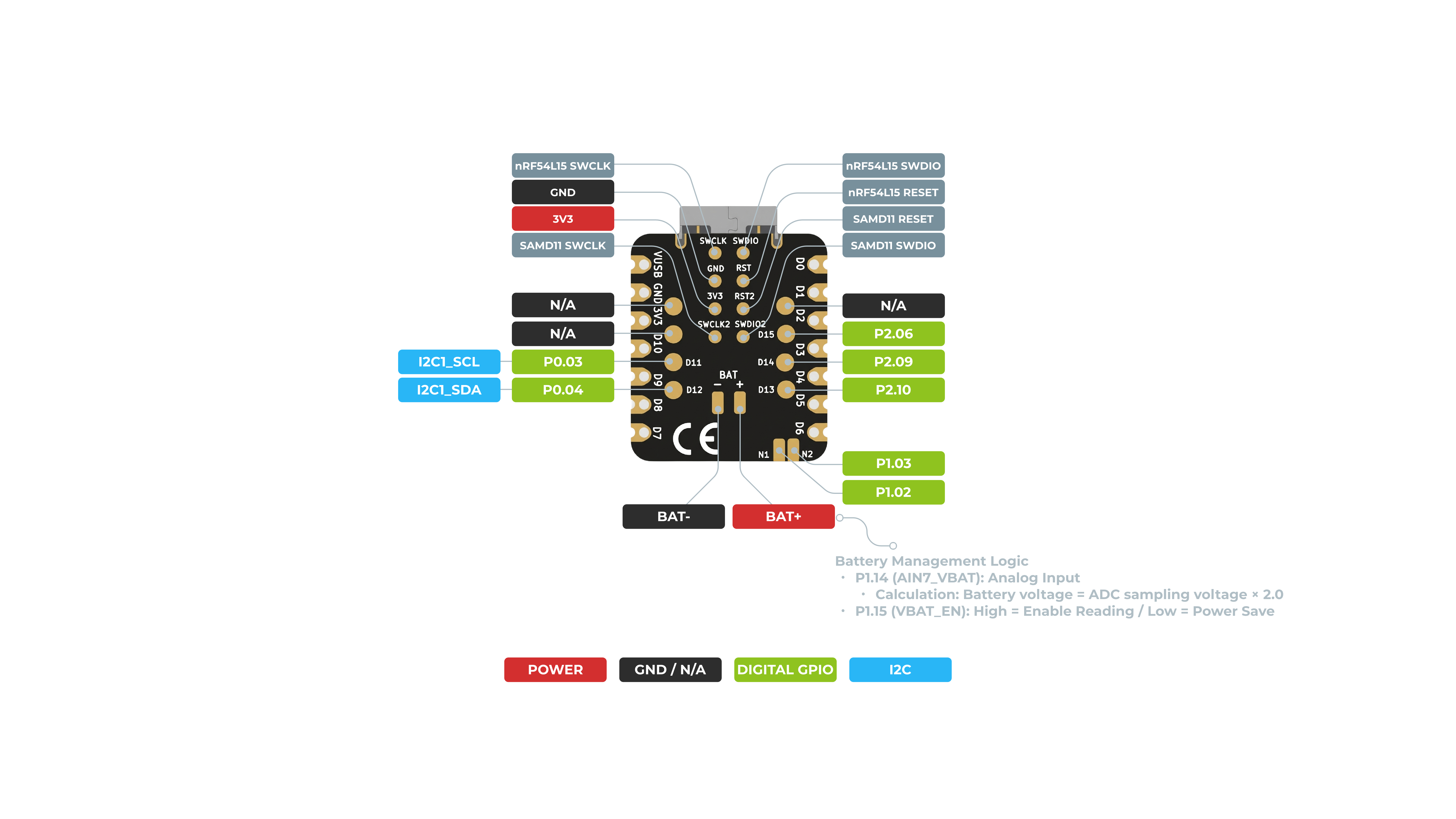
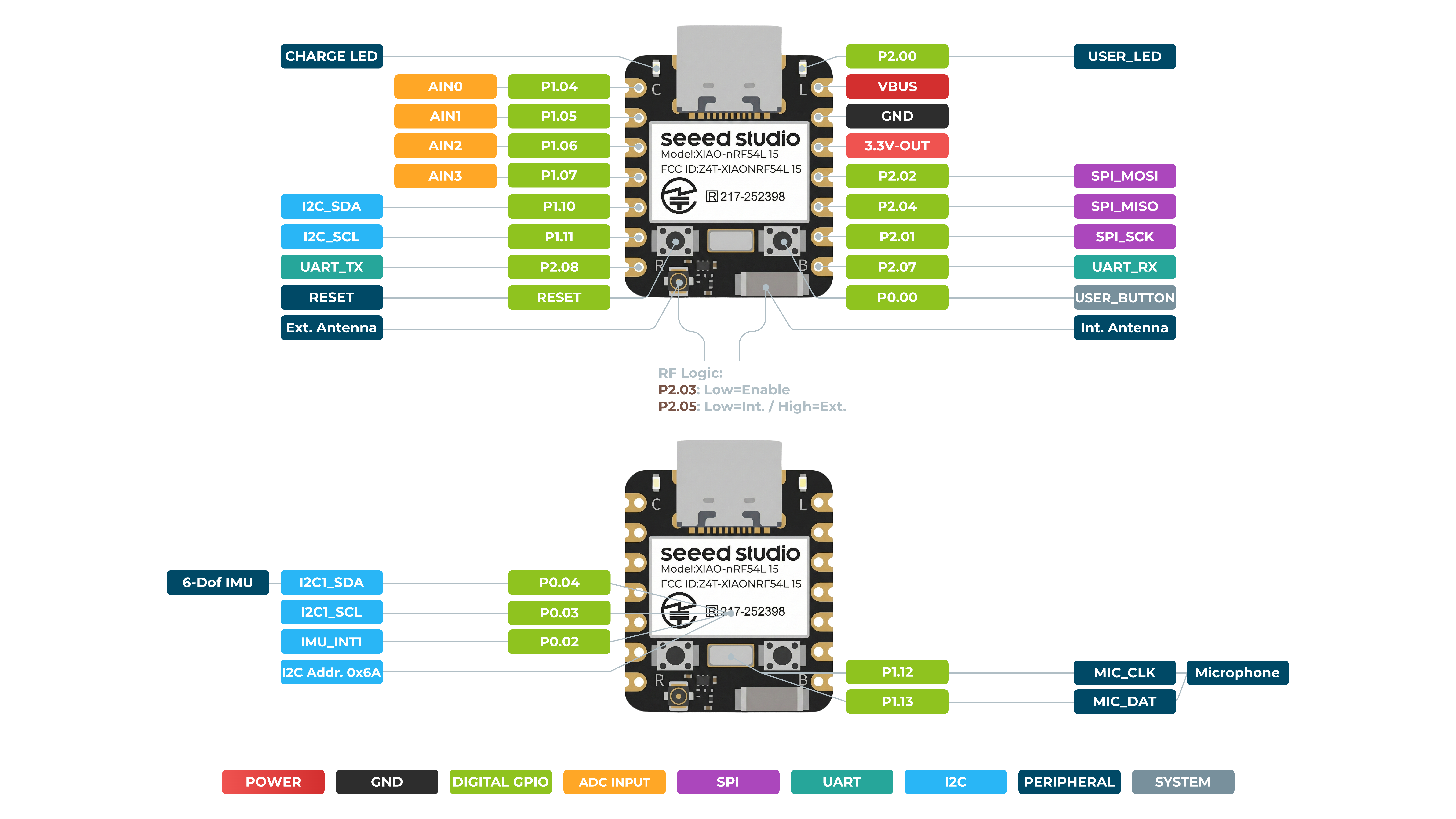
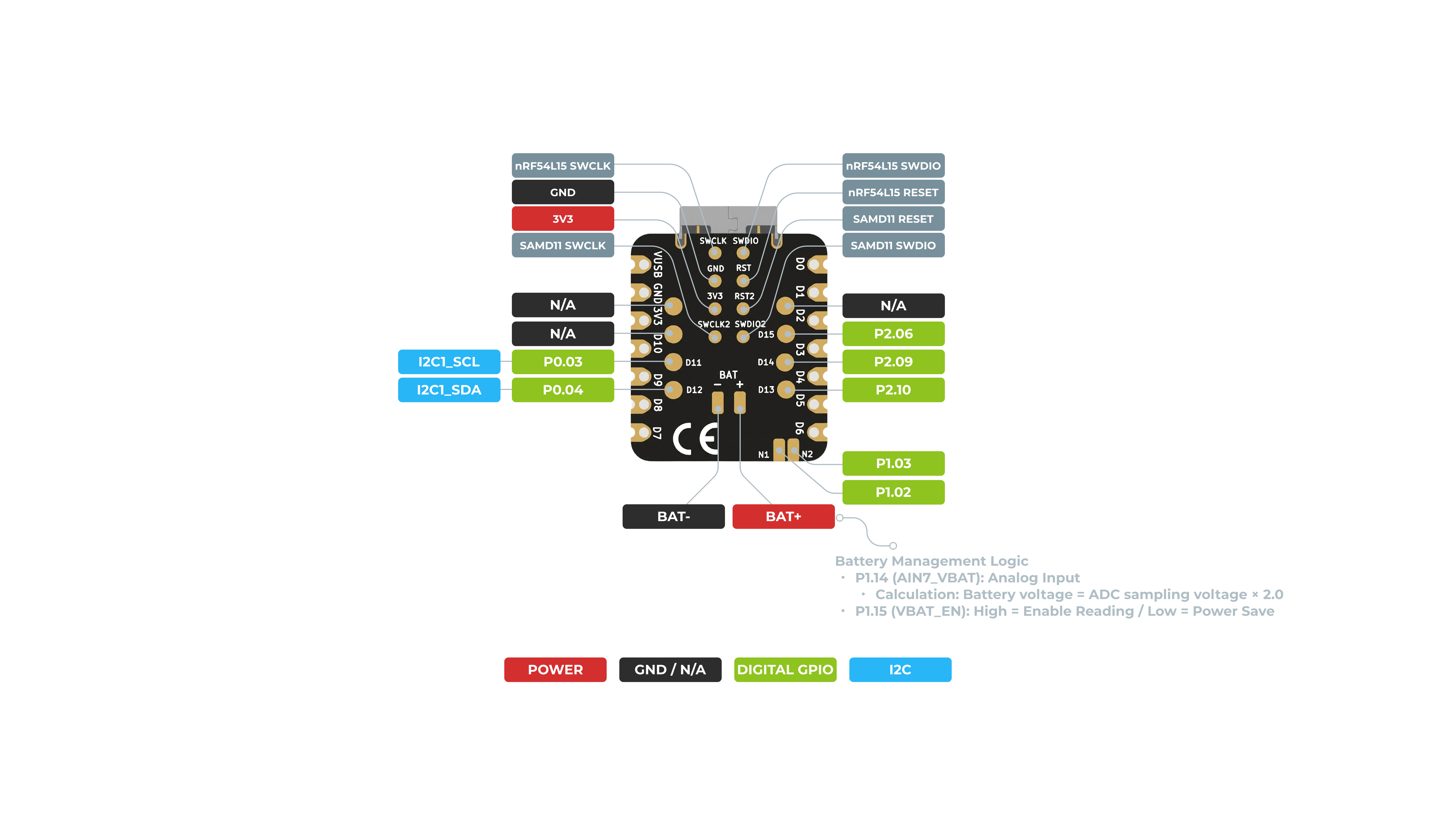
Botón de reinicio
El botón de reinicio se utiliza para realizar una operación de reinicio forzado en el dispositivo.
- Funcionalidad:
- Reinicio forzado: Al pulsar este botón se interrumpen inmediatamente todas las operaciones actuales del dispositivo y se provoca su reinicio, similar a un ciclo de encendido.
- Resolución de programas bloqueados: Cuando el programa en ejecución del dispositivo se bloquea, entra en un bucle infinito o deja de responder, pulsar el botón de reinicio es la forma más rápida de forzarlo a volver a un estado de funcionamiento normal.
- Sin impacto en el firmware: Una operación de reinicio no borra ni modifica el firmware ya programado en el dispositivo. Simplemente reinicia la aplicación que se está ejecutando.
Botón de usuario
El botón de usuario es una entrada programable y versátil que ofrece un control flexible dentro de tus aplicaciones.
Funcionalidad:
-
Entrada personalizable: A diferencia de la función fija del botón de reinicio, la acción del botón de usuario está totalmente definida por el firmware que programes.
-
Disparo de eventos: Se puede programar para activar eventos específicos, controlar diferentes funcionalidades o actuar como una entrada de propósito general para tus aplicaciones.
Digital
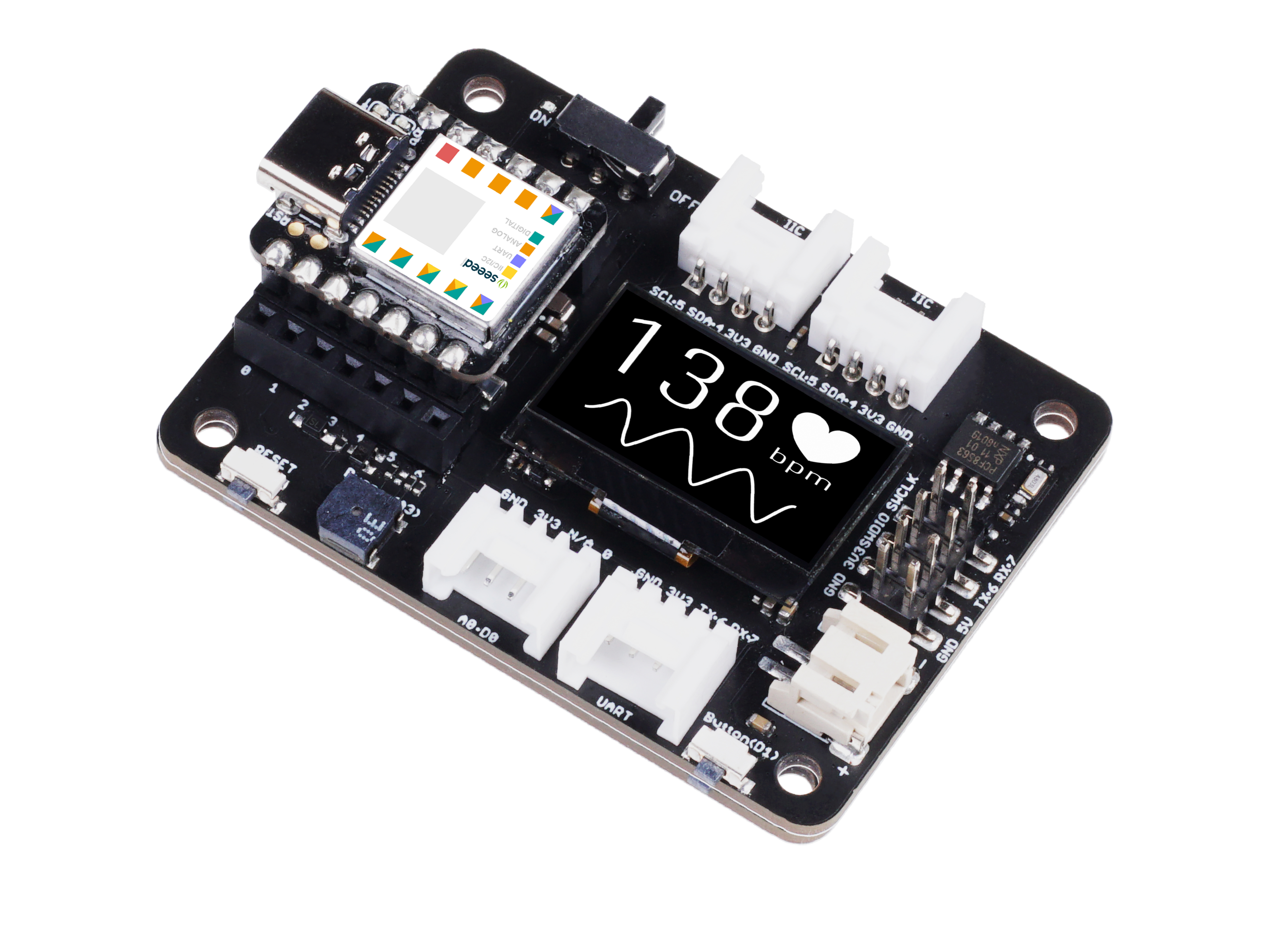
Preparación de hardware
| Seeed Studio XIAO nRF54L15 Sense | Seeed Studio Expansion Base for XIAO with Grove OLED | Grove - Relay |
|---|---|---|
 |  |  |
Implementación de software
#include <zephyr/kernel.h>
#include <zephyr/drivers/gpio.h>
#include <zephyr/logging/log.h>


LOG_MODULE_REGISTER(main_app, CONFIG_LOG_DEFAULT_LEVEL);

static const struct gpio_dt_spec button = GPIO_DT_SPEC_GET(DT_ALIAS(sw1), gpios); // Get the button device from the device tree alias
static const struct gpio_dt_spec relay = GPIO_DT_SPEC_GET(DT_ALIAS(relay0), gpios); // Get the relay device from the device tree alias

int main(void)
{
    int ret;

    LOG_INF("Starting Zephyr button and relay example...");

    /* Check if GPIO devices are ready */
    if (!gpio_is_ready_dt(&button)) {
        LOG_ERR("Button device %s is not ready", button.port->name);
        return -1;
    }

    if (!gpio_is_ready_dt(&relay)) {
        LOG_ERR("Relay device %s is not ready", relay.port->name);
        return -1;
    }

    /* Configure button pin as input mode */
    ret = gpio_pin_configure_dt(&button, GPIO_INPUT);
    if (ret != 0) {
        LOG_ERR("Failed to configure %s pin %d (error %d)", button.port->name, button.pin, ret);
        return -1;
    }

    /* Configure relay pin as output mode */
    ret = gpio_pin_configure_dt(&relay, GPIO_OUTPUT_ACTIVE);
    if (ret != 0) {
        LOG_ERR("Failed to configure %s pin %d (error %d)", relay.port->name, relay.pin, ret);
        return -1;
    }

    LOG_INF("Press the button to toggle the relay...");

    while (1) {
        /* Read button state */
        int button_state = gpio_pin_get_dt(&button);

        /* Check if read is successful */
        if (button_state < 0) {
            LOG_ERR("Error reading button pin: %d", button_state);
            return -1;
        }

        if (button_state == 0) { // Button pressed (ACTIVE_LOW)
            gpio_pin_set_dt(&relay, 1); // Turn on relay (high level)
        } else { // Button not pressed
            gpio_pin_set_dt(&relay, 0); // Turn off relay (low level)
        }

        k_msleep(10); /* Short delay to avoid busy looping */
    }
    return 0;
}
Configuración del Device Tree
static const struct gpio_dt_spec button = GPIO_DT_SPEC_GET(DT_ALIAS(sw1), gpios);
- Esta línea de código utiliza el sistema de device tree de Zephyr para obtener la información del dispositivo GPIO del botón mediante un alias llamado sw1. Este enfoque desacopla el código de los pines de hardware específicos y mejora la portabilidad.
static const struct gpio_dt_spec relay = GPIO_DT_SPEC_GET(DT_ALIAS(relay0), gpios);
- De nuevo, esta línea de código obtiene información sobre el dispositivo GPIO del relé llamado relay0.
Comprobación de disponibilidad del dispositivo
if (!gpio_is_ready_dt(&button)) and if (!gpio_is_ready_dt(&relay))
- Antes de que el programa comience a realizar cualquier operación, el código comprueba si los dispositivos del botón y del relé se han inicializado correctamente y están listos. Esta es una buena práctica en la programación de controladores en Zephyr y evita que el programa se bloquee si los dispositivos no están configurados correctamente.
Configuración de pines
gpio_pin_configure_dt(&button, GPIO_INPUT);
- Esta línea de código configura el pin GPIO del botón en modo de entrada. Este es un paso necesario para leer el nivel del pin, y el programa supervisará el nivel de voltaje del pin para determinar si el botón está pulsado.
gpio_pin_configure_dt(&relay, GPIO_OUTPUT_ACTIVE);
- Esta línea de código configura el pin GPIO del relé en modo de salida. La marca
GPIO_OUTPUT_ACTIVEsuele indicar que el pin estará activo después de la configuración, en preparación para controlar el relé.
Lógica del bucle principal
while (1): El código entra en un bucle infinito que realiza continuamente las siguientes acciones.
int button_state = gpio_pin_get_dt(&button);: En cada bucle, el programa lee el estado de nivel actual de los pines del botón.
if (button_state == 0): Esta lógica comprueba si el botón está presionado. En muchos diseños de circuitos, al presionar un botón se conecta el pin a tierra (GND), lo que da como resultado un nivel de 0 (es decir, bajo).
gpio_pin_set_dt(&relay, 1);: Si el estado del botón es 0 (presionado), entonces el pin del relé se establece en 1 (alto), lo que cierra el relé y enciende el dispositivo (por ejemplo, una lámpara) al que está conectado.
else: Si el botón no está presionado (el estado es 1), perform gpio_pin_set_dt(&relay, 0); para establecer el pin del relé en 0 (bajo), lo que cierra el relé y apaga el dispositivo al que está conectado.
k_msleep(10);: el código añade un breve retardo de 10 milisegundos al final de cada bucle para evitar que la CPU esté ocupada, etc. Este es un manejo simple de anti‑rebote. Este es un manejo simple de anti‑rebote que evita múltiples disparos debido al rebote físico de los botones y también reduce el consumo de energía.
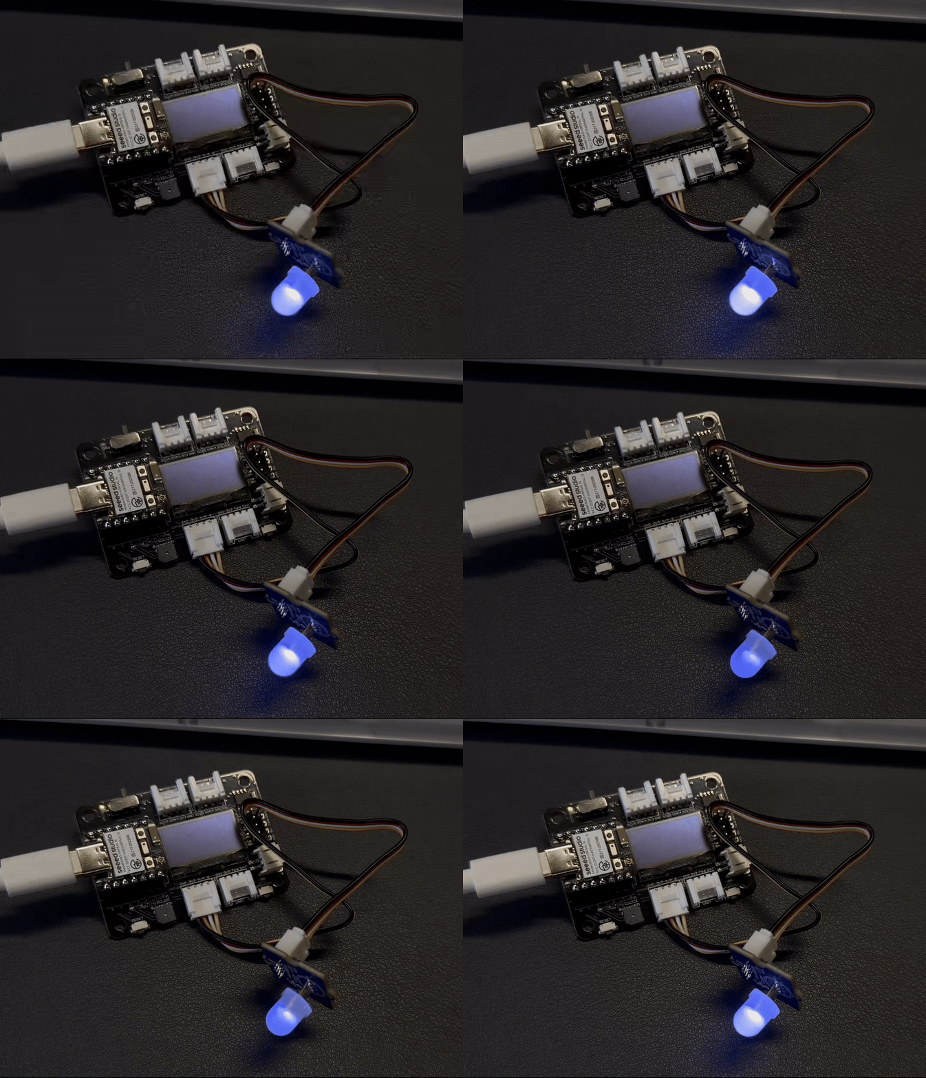
Gráfico de resultado
Analógico
Preparación de hardware
| Seeed Studio XIAO nRF54L15 Sense | Grove-Variable Color LED | Grove-Rotary Angle Sensor | Seeed Studio Grove Base for XIAO |
|---|---|---|---|
|  |  |  |
Implementación de software
#include <zephyr/kernel.h>
#include <zephyr/drivers/adc.h>
#include <zephyr/drivers/pwm.h>
#include <zephyr/logging/log.h>

// Register log module
LOG_MODULE_REGISTER(pot_pwm_example, CONFIG_LOG_DEFAULT_LEVEL);

// --- ADC Configuration ---
#if !DT_NODE_EXISTS(DT_PATH(zephyr_user)) || \
    !DT_NODE_HAS_PROP(DT_PATH(zephyr_user), io_channels)
#error "No suitable devicetree overlay specified for ADC channels"
#endif

#define DT_SPEC_AND_COMMA(node_id, prop, idx) \
    ADC_DT_SPEC_GET_BY_IDX(node_id, idx),

static const struct adc_dt_spec adc_channels[] = {
    DT_FOREACH_PROP_ELEM(DT_PATH(zephyr_user), io_channels, DT_SPEC_AND_COMMA)
};

// Define the index of the potentiometer ADC channel in the adc_channels array
#define POTENTIOMETER_ADC_CHANNEL_IDX 1

// --- PWM Configuration ---
// Get PWM LED device
static const struct pwm_dt_spec led = PWM_DT_SPEC_GET(DT_ALIAS(pwm_led));

// Define PWM period as 1 millisecond (1,000,000 nanoseconds)
// This corresponds to a 1 kHz PWM frequency, suitable for LED brightness adjustment without visible flicker
#define PWM_PERIOD_NS 1000000UL

int main(void)
{
    int ret;
    uint16_t adc_raw_value;
    int32_t adc_millivolts;

    LOG_INF("Starting Zephyr Potentiometer to PWM example...");

    // --- ADC initialization and setup ---
    if (!adc_is_ready_dt(&adc_channels[POTENTIOMETER_ADC_CHANNEL_IDX])) {
        LOG_ERR("ADC controller device %s not ready", adc_channels[POTENTIOMETER_ADC_CHANNEL_IDX].dev->name);
        return 0;
    }

    ret = adc_channel_setup_dt(&adc_channels[POTENTIOMETER_ADC_CHANNEL_IDX]);
    if (ret < 0) {
        LOG_ERR("Could not setup ADC channel for potentiometer (%d)", ret);
        return 0;
    }
    LOG_INF("ADC device %s, channel %d ready for potentiometer.",
            adc_channels[POTENTIOMETER_ADC_CHANNEL_IDX].dev->name,
            adc_channels[POTENTIOMETER_ADC_CHANNEL_IDX].channel_id);

    // --- PWM initialization and setup ---
    if (!device_is_ready(led.dev)) {
        LOG_ERR("Error: PWM device %s is not ready", led.dev->name);
        return 0;
    }
    LOG_INF("PWM Period for LED set to %lu ns (%.1f Hz)",
            PWM_PERIOD_NS, (double)NSEC_PER_SEC / PWM_PERIOD_NS); // Use PWM_PERIOD_NS instead of led.period


    // ADC sequence configuration
    struct adc_sequence sequence = {
        .buffer = &adc_raw_value,
        .buffer_size = sizeof(adc_raw_value),
        .resolution = adc_channels[POTENTIOMETER_ADC_CHANNEL_IDX].resolution,
    };

    // --- Main loop ---
    while (1) {
        (void)adc_sequence_init_dt(&adc_channels[POTENTIOMETER_ADC_CHANNEL_IDX], &sequence);

        ret = adc_read(adc_channels[POTENTIOMETER_ADC_CHANNEL_IDX].dev, &sequence);
        if (ret < 0) {
            LOG_ERR("Error %d: ADC read failed for channel %d",
                    ret, adc_channels[POTENTIOMETER_ADC_CHANNEL_IDX].channel_id);
            k_msleep(100);
            continue;
        }

        int sensor_value = adc_raw_value;

        uint32_t max_adc_raw = (1U << adc_channels[POTENTIOMETER_ADC_CHANNEL_IDX].resolution) - 1;

        // --- Map ADC raw value to PWM duty cycle ---
        uint32_t output_duty_ns = (PWM_PERIOD_NS * sensor_value) / max_adc_raw;

        // Set PWM duty cycle
        ret = pwm_set_dt(&led, PWM_PERIOD_NS, output_duty_ns);
        if (ret < 0) {
            LOG_ERR("Error %d: failed to set PWM duty cycle.", ret);
        }

        // --- Print information ---
        adc_millivolts = sensor_value;
        ret = adc_raw_to_millivolts_dt(&adc_channels[POTENTIOMETER_ADC_CHANNEL_IDX], &adc_millivolts);
        if (ret < 0) {
            LOG_WRN("ADC to mV conversion not supported/failed: %d", ret);
            LOG_INF("Sensor Raw Value = %d\tOutput Duty (ns) = %u", sensor_value, output_duty_ns);
        } else {
            LOG_INF("Sensor Raw Value = %d (%d mV)\tOutput Duty (ns) = %u",
                    sensor_value, adc_millivolts, output_duty_ns);
        }

        k_msleep(100);
    }
    return 0;
}
Configuración de los dispositivos ADC (Convertidor Analógico‑Digital) y PWM (Modulación por Ancho de Pulso)
-
Módulo de registro pot_pwm_example:
- LOG_MODULE_REGISTER(pot_pwm_example, CONFIG_LOG_DEFAULT_LEVEL): Esto registra un módulo de registro llamado pot_pwm_example y establece su nivel de registro en la configuración predeterminada del sistema, lo que facilita la depuración.
-
Configuración del ADC:
-
#if !DT_NODE_EXISTS(DT_PATH(zephyr_user)) ... #endif: Esta directiva del preprocesador es una comprobación del Device Tree que garantiza que exista un archivo de superposición válido que contenga las definiciones de los canales del ADC. Esto exige que el usuario proporcione la configuración correcta para el hardware específico.
-
static const struct adc_dt_spec adc_channels[];: Esta parte del código aprovecha el Device Tree de Zephyr para obtener automáticamente información de todos los canales de ADC configurados. Este enfoque hace que el código sea flexible y portátil entre diferentes hardware sin cambios de configuración manuales.
-
#define POTENTIOMETER_ADC_CHANNEL_IDX 1: Se define una macro para especificar a qué canal del arreglo adc_channels está conectado el potenciómetro.
-
-
Configuración de PWM:
-
static const struct pwm_dt_spec led = PWM_DT_SPEC_GET(DT_ALIAS(pwm_led));: Esta línea obtiene la información del dispositivo PWM para el alias pwm_led desde el Device Tree. Esta es una práctica estándar de Zephyr para buscar y referenciar dispositivos de hardware.
-
#define PWM_PERIOD_NS 1000000UL: Esto define el período de la señal PWM como 1 milisegundo (1 000 000 nanosegundos), lo que corresponde a una frecuencia de 1 kHz. Esta frecuencia es adecuada para el control de brillo de un LED, ya que es lo suficientemente alta como para evitar parpadeos visibles.
-
Inicialización y configuración
-
Información de registro:
- LOG_INF("Starting Zephyr Potentiometer to PWM example...");: Se imprime un mensaje de registro informativo al inicio del programa para notificar al usuario que el ejemplo ha comenzado.
-
Inicialización del ADC:
-
!adc_is_ready_dt(): Antes de intentar usar el dispositivo ADC, se realiza una comprobación para confirmar que está listo. Si el dispositivo no está listo, se registra un error y el programa termina.
-
adc_channel_setup_dt(): Esta función configura el canal específico del ADC conectado al potenciómetro, incluida su resolución y ganancia.
-
-
Inicialización del PWM:
-
!device_is_ready(led.dev): De forma similar al ADC, esta línea comprueba si el dispositivo PWM está listo. Si no lo está, se registra un error y el programa termina.
-
LOG_INF(...): Se imprimen la información del período y la frecuencia del PWM para ayudar al usuario a confirmar la configuración.
-
-
Configuración de la secuencia del ADC:
- struct adc_sequence sequence: Se define una estructura adc_sequence para describir una única operación de conversión del ADC. Especifica el búfer (adc_raw_value) para almacenar el resultado, su tamaño (sizeof(adc_raw_value)) y la resolución del ADC que se va a utilizar.
Bucle principal La lógica principal del código se ejecuta dentro de un bucle infinito while (1):
-
Lectura del ADC:
-
adc_sequence_init_dt(): La secuencia del ADC se inicializa para garantizar que se use la configuración correcta en cada lectura.
-
adc_read(): Esto desencadena una conversión del ADC para leer el valor analógico del potenciómetro. Si la lectura falla, se registra un error y el programa se pausa durante 100 milisegundos antes de continuar.
-
int sensor_value = adc_raw_value;: El valor bruto del ADC se asigna a la variable sensor_value.
-
-
Mapeo del valor del ADC al ciclo de trabajo del PWM:
-
uint32_t max_adc_raw: Esto calcula el valor bruto máximo posible del ADC.
-
uint32_t output_duty_ns = (PWM_PERIOD_NS * sensor_value) / max_adc_raw;: Esta es la lógica principal de mapeo. Escala el valor bruto del ADC (sensor_value) de forma proporcional al rango del período PWM (PWM_PERIOD_NS) para obtener un valor de ciclo de trabajo que ajusta el brillo del LED.
-
-
Configuración del ciclo de trabajo del PWM:
- pwm_set_dt(): Esta función aplica el nuevo ciclo de trabajo calculado (output_duty_ns) al dispositivo PWM, cambiando instantáneamente el brillo del LED.
-
Retardo:
- k_msleep(100): El programa se pausa durante 100 milisegundos después de cada bucle. Esto controla la frecuencia de las lecturas del ADC y las actualizaciones del PWM, evitando una carga excesiva de la CPU y proporcionando una experiencia de usuario estable.
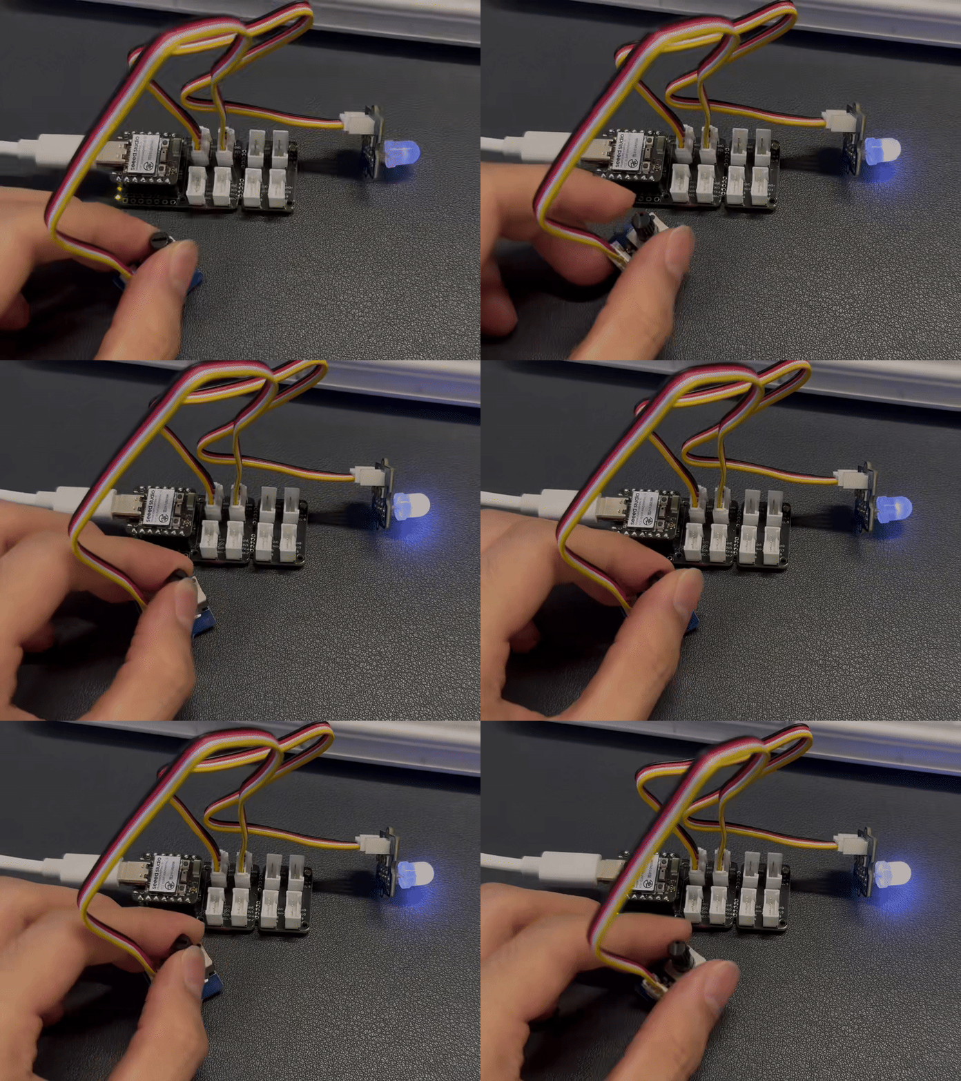
Gráfico de resultados
UART
Preparación de hardware
| Seeed Studio XIAO nRF54L15 Sense | Módulo L76K GNSS para Seeed Studio XIAO |
|---|---|
| 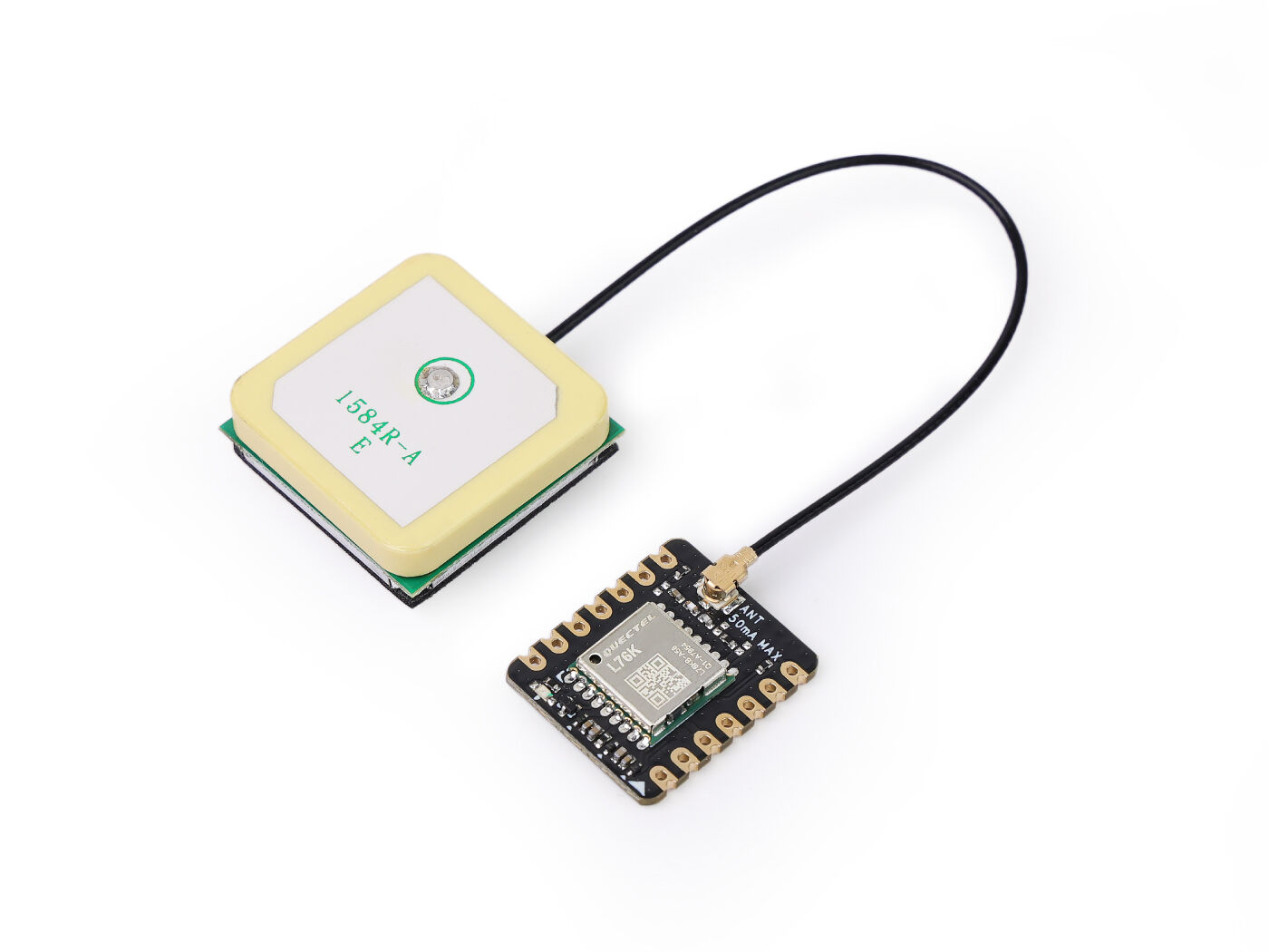 |
Implementación de software
Software
#include <zephyr/kernel.h>
#include <zephyr/device.h>
#include <zephyr/drivers/uart.h>
#include <zephyr/logging/log.h>
#include <nrfx_power.h>
#include <string.h>
#include <math.h>
#include <stdio.h>
#include <stdlib.h>

// Register log module
LOG_MODULE_REGISTER(gps_app, LOG_LEVEL_INF);

// Type definitions
#define UBYTE uint8_t
#define UWORD uint16_t
#define UDOUBLE uint32_t

// Buffer sizes
#define SENTENCE_SIZE 100
#define BUFFSIZE 800

// NMEA Commands
#define HOT_START "$PMTK101"
#define WARM_START "$PMTK102"
#define COLD_START "$PMTK103"
#define FULL_COLD_START "$PMTK104"
#define SET_PERPETUAL_STANDBY_MODE "$PMTK161"
#define SET_PERIODIC_MODE "$PMTK225"
#define SET_NORMAL_MODE "$PMTK225,0"
#define SET_PERIODIC_BACKUP_MODE "$PMTK225,1,1000,2000"
#define SET_PERIODIC_STANDBY_MODE "$PMTK225,2,1000,2000"
#define SET_PERPETUAL_BACKUP_MODE "$PMTK225,4"
#define SET_ALWAYSLOCATE_STANDBY_MODE "$PMTK225,8"
#define SET_ALWAYSLOCATE_BACKUP_MODE "$PMTK225,9"
#define SET_POS_FIX "$PMTK220"
#define SET_POS_FIX_100MS "$PMTK220,100"
#define SET_POS_FIX_200MS "$PMTK220,200"
#define SET_POS_FIX_400MS "$PMTK220,400"
#define SET_POS_FIX_800MS "$PMTK220,800"
#define SET_POS_FIX_1S "$PMTK220,1000"
#define SET_POS_FIX_2S "$PMTK220,2000"
#define SET_POS_FIX_4S "$PMTK220,4000"
#define SET_POS_FIX_8S "$PMTK220,8000"
#define SET_POS_FIX_10S "$PMTK220,10000"
#define SET_SYNC_PPS_NMEA_OFF "$PMTK255,0"
#define SET_SYNC_PPS_NMEA_ON "$PMTK255,1"
#define SET_NMEA_BAUDRATE "$PMTK251"
#define SET_NMEA_BAUDRATE_115200 "$PMTK251,115200"
#define SET_NMEA_BAUDRATE_57600 "$PMTK251,57600"
#define SET_NMEA_BAUDRATE_38400 "$PMTK251,38400"
#define SET_NMEA_BAUDRATE_19200 "$PMTK251,19200"
#define SET_NMEA_BAUDRATE_14400 "$PMTK251,14400"
#define SET_NMEA_BAUDRATE_9600 "$PMTK251,9600"
#define SET_NMEA_BAUDRATE_4800 "$PMTK251,4800"
#define SET_REDUCTION "$PMTK314,-1"
#define SET_NMEA_OUTPUT "$PMTK314,0,1,1,1,1,0,0,0,0,0,0,0,0,0,0,0,0,0,0"

// Struct definitions
typedef struct
{
 double Lon;    // GPS Longitude
 double Lat;    // GPS Latitude
 char Lon_area; // E or W
 char Lat_area; // N or S
 UBYTE Time_H;  // Time Hour
 UBYTE Time_M;  // Time Minute
 UBYTE Time_S;  // Time Second
 UBYTE Status;  // 1: Successful positioning, 0: Positioning failed
} GNRMC;

typedef struct
{
 double Lon;
 double Lat;
} Coordinates;

// Global variables and constants
char const Temp[16] = {'0', '1', '2', '3', '4', '5', '6', '7', '8', '9', 'A', 'B', 'C', 'D', 'E', 'F'};
static const double pi = 3.14159265358979324;
static const double a = 6378245.0;
static const double ee = 0.00669342162296594323;
static const double x_pi = 3.14159265358979324 * 3000.0 / 180.0;

static char buff_t[BUFFSIZE] = {0};
static GNRMC GPS;

// UART device and buffers
static const struct device *uart_dev;
static char latest_gnrmc[SENTENCE_SIZE];
static volatile bool new_gnrmc_available = false;

// Function prototypes
void DEV_Uart_SendByte(char data);
void DEV_Uart_SendString(char *data);
void L76X_Send_Command(char *data);
GNRMC L76X_Gat_GNRMC(void);
Coordinates L76X_Baidu_Coordinates(void);
Coordinates L76X_Google_Coordinates(void);
static double transformLat(double x, double y);
static double transformLon(double x, double y);
static Coordinates bd_encrypt(Coordinates gg);
static Coordinates transform(Coordinates gps);

// UART interrupt callback
static void uart_callback(const struct device *dev, void *user_data)
{
 ARG_UNUSED(user_data);
 static char temp_buffer[SENTENCE_SIZE];
 static int temp_index = 0;

 while (uart_irq_update(dev) && uart_irq_is_pending(dev))
 {
  if (uart_irq_rx_ready(dev))
  {
   uint8_t byte;
   if (uart_fifo_read(dev, &byte, 1) == 1)
   {
    if (byte == '\n')
    {
     temp_buffer[temp_index] = '\0';
     if (strncmp(temp_buffer, "$GNRMC", 6) == 0 || strncmp(temp_buffer, "$PNRMC", 6) == 0)
     {
      strncpy(latest_gnrmc, temp_buffer, SENTENCE_SIZE);
      new_gnrmc_available = true;
     }
     temp_index = 0;
    }
    else
    {
     if (temp_index < SENTENCE_SIZE - 1)
     {
      temp_buffer[temp_index++] = byte;
     }
     else
     {
      temp_index = 0; // Reset on overflow
     }
    }
   }
  }
 }
}

// Main function
int main(void)
{
 // Request constant latency mode for power management
 nrfx_power_constlat_mode_request();
 LOG_INF("Starting L76X GPS Module Example");

 // Initialize UART device
 uart_dev = DEVICE_DT_GET(DT_NODELABEL(xiao_serial));
 if (!device_is_ready(uart_dev))
 {
  LOG_ERR("UART device not ready!");
  return -1;
 }
 LOG_INF("UART device initialized.");

 // Configure UART interrupt
 if (uart_irq_callback_user_data_set(uart_dev, uart_callback, NULL) != 0)
 {
  LOG_ERR("Failed to set UART callback!");
  return -1;
 }
 uart_irq_rx_enable(uart_dev);
 LOG_INF("UART interrupt enabled.");

 // Initialize GPS module
 L76X_Send_Command(SET_NMEA_OUTPUT);
 k_msleep(100);
 L76X_Send_Command(SET_POS_FIX_1S);
 k_msleep(100);

 LOG_INF("GPS module initialized. Waiting for data...");

 while (true)
 {
  // Check for new GNRMC sentence
  if (new_gnrmc_available)
  {
   strncpy(buff_t, latest_gnrmc, BUFFSIZE);
   new_gnrmc_available = false;

   // Log raw GNRMC sentence for debugging
   LOG_INF("Raw GNRMC: %s", buff_t);

   // Parse GNRMC data
   GPS = L76X_Gat_GNRMC();

   // Output GPS data
   LOG_INF("\n--- GPS Data ---");
   LOG_INF("Time (GMT+8): %02d:%02d:%02d", GPS.Time_H, GPS.Time_M, GPS.Time_S);
   if (GPS.Status == 1)
   {
    LOG_INF("Latitude (WGS-84): %.6f %c", GPS.Lat, GPS.Lat_area);
    LOG_INF("Longitude (WGS-84): %.6f %c", GPS.Lon, GPS.Lon_area);

    // Coordinate conversion
    Coordinates baidu_coords = L76X_Baidu_Coordinates();
    LOG_INF("Baidu Latitude: %.6f", baidu_coords.Lat);
    LOG_INF("Baidu Longitude: %.6f", baidu_coords.Lon);

    Coordinates google_coords = L76X_Google_Coordinates();
    LOG_INF("Google Latitude: %.6f", google_coords.Lat);
    LOG_INF("Google Longitude: %.6f", google_coords.Lon);
    LOG_INF("GPS positioning successful.");
   }
   else
   {
    LOG_INF("GPS positioning failed or no valid data.");
   }
  }
  else
  {
   LOG_INF("No new GNRMC data available.");
  }

  k_msleep(2000); // Wait 2 seconds before next reading
 }

 return 0;
}

// Send a single byte
void DEV_Uart_SendByte(char data)
{
 uart_poll_out(uart_dev, data);
}

// Send a string
void DEV_Uart_SendString(char *data)
{
 while (*data)
 {
  DEV_Uart_SendByte(*data++);
 }
}

// Send L76X command with checksum
void L76X_Send_Command(char *data)
{
 char Check = data[1], Check_char[3] = {0};
 UBYTE i = 0;
 DEV_Uart_SendByte('\r');
 DEV_Uart_SendByte('\n');

 for (i = 2; data[i] != '\0'; i++)
 {
  Check ^= data[i]; // Calculate checksum
 }
 Check_char[0] = Temp[Check / 16 % 16];
 Check_char[1] = Temp[Check % 16];
 Check_char[2] = '\0';

 DEV_Uart_SendString(data);
 DEV_Uart_SendByte('*');
 DEV_Uart_SendString(Check_char);
 DEV_Uart_SendByte('\r');
 DEV_Uart_SendByte('\n');
}

// Parse GNRMC data
GNRMC L76X_Gat_GNRMC(void)
{
 GNRMC gps = {0}; // Initialize with zeros
 UWORD add = 0, x = 0, z = 0, i = 0;
 UDOUBLE Time = 0;

 add = 0;
 while (add < BUFFSIZE)
 {
  // Look for GNRMC or PNRMC sentence
  if (buff_t[add] == '$' && buff_t[add + 1] == 'G' && (buff_t[add + 2] == 'N' || buff_t[add + 2] == 'P') &&
   buff_t[add + 3] == 'R' && buff_t[add + 4] == 'M' && buff_t[add + 5] == 'C')
  {
   x = 0;
   for (z = 0; x < 12; z++)
   {
    if (buff_t[add + z] == '\0')
    {
     break;
    }
    if (buff_t[add + z] == ',')
    {
     x++;
     if (x == 1)
     { // Time field
      if (buff_t[add + z + 1] != ',')
      { // Check if time field is not empty
       Time = 0;
       for (i = 0; buff_t[add + z + i + 1] != '.'; i++)
       {
        if (buff_t[add + z + i + 1] == '\0' || buff_t[add + z + i + 1] == ',')
        {
         break;
        }
        Time = (buff_t[add + z + i + 1] - '0') + Time * 10;
       }
       gps.Time_H = Time / 10000 + 8; // Adjust for GMT+8
       gps.Time_M = (Time / 100) % 100;
       gps.Time_S = Time % 100;
       if (gps.Time_H >= 24)
       {
        gps.Time_H = gps.Time_H - 24;
       }
      }
     }
     else if (x == 2)
     { // Status field
      if (buff_t[add + z + 1] == 'A')
      {
       gps.Status = 1; // Position successful
      }
      else
      {
       gps.Status = 0; // Positioning failed
       break;   // Exit early if invalid
      }
     }
     else if (x == 3)
     { // Latitude field
      if (buff_t[add + z + 1] != ',')
      { // Check if latitude field is not empty
       double latitude_val = 0;
       UBYTE decimal_found = 0;
       double decimal_multiplier = 0.1;

       int k = 1;
       while (buff_t[add + z + k] != ',' && buff_t[add + z + k] != '\0')
       {
        if (buff_t[add + z + k] == '.')
        {
         decimal_found = 1;
         k++;
         continue;
        }
        if (!decimal_found)
        {
         latitude_val = latitude_val * 10 + (buff_t[add + z + k] - '0');
        }
        else
        {
         latitude_val = latitude_val + (buff_t[add + z + k] - '0') * decimal_multiplier;
         decimal_multiplier *= 0.1;
        }
        k++;
       }
       gps.Lat = latitude_val;
       gps.Lat_area = buff_t[add + z + k + 1]; // N or S
       z += k + 1;
      }
      else
      {
       gps.Status = 0; // Invalid data
       break;
      }
     }
     else if (x == 5)
     { // Longitude field
      if (buff_t[add + z + 1] != ',')
      { // Check if longitude field is not empty
       double longitude_val = 0;
       UBYTE decimal_found = 0;
       double decimal_multiplier = 0.1;

       int k = 1;
       while (buff_t[add + z + k] != ',' && buff_t[add + z + k] != '\0')
       {
        if (buff_t[add + z + k] == '.')
        {
         decimal_found = 1;
         k++;
         continue;
        }
        if (!decimal_found)
        {
         longitude_val = longitude_val * 10 + (buff_t[add + z + k] - '0');
        }
        else
        {
         longitude_val = longitude_val + (buff_t[add + z + k] - '0') * decimal_multiplier;
         decimal_multiplier *= 0.1;
        }
        k++;
       }
       gps.Lon = longitude_val;
       gps.Lon_area = buff_t[add + z + k + 1]; // E or W
       z += k + 1;
       break;
      }
      else
      {
       gps.Status = 0; // Invalid data
       break;
      }
     }
    }
   }
   break;
  }
  add++;
 }
 return gps;
}

// Convert to Baidu coordinates (BD-09)
Coordinates L76X_Baidu_Coordinates(void)
{
 Coordinates wgs84_coords;
 wgs84_coords.Lat = GPS.Lat;
 wgs84_coords.Lon = GPS.Lon;

 Coordinates gcj02_coords = transform(wgs84_coords);
 Coordinates bd09_coords = bd_encrypt(gcj02_coords);
 return bd09_coords;
}

// Convert to Google coordinates (GCJ-02)
Coordinates L76X_Google_Coordinates(void)
{
 Coordinates wgs84_coords;
 wgs84_coords.Lat = GPS.Lat;
 wgs84_coords.Lon = GPS.Lon;

 Coordinates gcj02_coords = transform(wgs84_coords);
 return gcj02_coords;
}

// Coordinate transformation helper functions
static double transformLat(double x, double y)
{
 double ret = -100.0 + 2.0 * x + 3.0 * y + 0.2 * y * y + 0.1 * x * y + 0.2 * sqrt(fabs(x));
 ret += (20.0 * sin(6.0 * x * pi) + 20.0 * sin(2.0 * x * pi)) * 2.0 / 3.0;
 ret += (20.0 * sin(y * pi) + 40.0 * sin(y / 3.0 * pi)) * 2.0 / 3.0;
 ret += (160.0 * sin(y / 12.0 * pi) + 320 * sin(y * pi / 30.0)) * 2.0 / 3.0;
 return ret;
}

static double transformLon(double x, double y)
{
 double ret = 300.0 + x + 2.0 * y + 0.1 * x * x + 0.1 * x * y + 0.1 * sqrt(fabs(x));
 ret += (20.0 * sin(6.0 * x * pi) + 20.0 * sin(2.0 * x * pi)) * 2.0 / 3.0;
 ret += (20.0 * sin(x * pi) + 40.0 * sin(x / 3.0 * pi)) * 2.0 / 3.0;
 ret += (150.0 * sin(x / 12.0 * pi) + 300.0 * sin(x / 30.0 * pi)) * 2.0 / 3.0;
 return ret;
}

static Coordinates bd_encrypt(Coordinates gg)
{
 Coordinates bd;
 double x = gg.Lon, y = gg.Lat;
 double z = sqrt(x * x + y * y) + 0.00002 * sin(y * x_pi);
 double theta = atan2(y, x) + 0.000003 * cos(x * x_pi);
 bd.Lon = z * cos(theta) + 0.0065;
 bd.Lat = z * sin(theta) + 0.006;
 return bd;
}

static Coordinates transform(Coordinates gps)
{
 Coordinates gg;
 double dLat = transformLat(gps.Lon - 105.0, gps.Lat - 35.0);
 double dLon = transformLon(gps.Lon - 105.0, gps.Lat - 35.0);
 double radLat = gps.Lat / 180.0 * pi;
 double magic = sin(radLat);
 magic = 1 - ee * magic * magic;
 double sqrtMagic = sqrt(magic);
 dLat = (dLat * 180.0) / ((a * (1 - ee)) / (magic * sqrtMagic) * pi);
 dLon = (dLon * 180.0) / (a / sqrtMagic * cos(radLat) * pi);
 gg.Lat = gps.Lat + dLat;
 gg.Lon = gps.Lon + dLon;
 return gg;
}
Configuración e inicialización del módulo GPS
- Módulo de registro
gps_app:
-LOG_MODULE_REGISTER(gps_app, LOG_LEVEL_INF): Esto registra un módulo de registro llamado gps_app y establece su nivel de registro en INFO. Esto permite que el programa emita información a través del sistema de registro de Zephyr, lo cual es útil para la depuración y la monitorización.
- Definiciones de tipos y macros:
-UBYTE, UWORD, UDOUBLE:Estos son alias de tipos enteros sin signo personalizados que mejoran la legibilidad del código al aclarar el tamaño esperado de las variables.
-
SENTENCE_SIZE, BUFFSIZE:Estos definen tamaños fijos para los búferes utilizados para almacenar sentencias NMEA y búferes de datos más grandes. -
Macros como
HOT_START, SET_NMEA_OUTPUT:Estas macros definen varios comandos del protocolo NMEA enviados al módulo GPS L76X para configurar su modo de funcionamiento, frecuencia de salida, velocidad en baudios, etc. -
Definiciones de estructuras:
-
GNRMC:Esta estructura se utiliza para almacenar información clave analizada de una sentencia NMEA GNRMC (GPS Recommended Minimum Specific data), incluyendo longitud, latitud, hora, estado y direcciones cardinales. -
Coordinates:Una estructura simple para almacenar la longitud y la latitud de una coordenada geográfica.
-
-
Variables globales y constantes:
buff_t:Un búfer global de tamaño BUFFSIZE utilizado para almacenar datos UART en bruto.
-GPS:Una instancia global de la estructura GNRMC utilizada para contener los datos GPS analizados.
-
uart_dev:Un puntero a la estructura del dispositivo UART, utilizado para la comunicación UART. -
new_gnrmc_available:Una bandera booleana volátil que se establece en true cuando se recibe una nueva sentencia GNRMC válida, notificando al bucle principal que hay nuevos datos disponibles para procesar. -
Función
uart_callback():-
Esta es una función de callback de interrupción UART que se activa cuando el UART recibe datos.
-
La función lee el FIFO del UART byte a byte y procesa los datos como una sentencia completa cuando se encuentra un carácter de nueva línea \n.
-
Función principal main()
-
Inicialización del sistema:
-
nrfx_power_constlat_mode_request():Solicita un modo de latencia constante para garantizar que la gestión de energía no interfiera con las operaciones en tiempo real. -
uart_dev = DEVICE_DT_GET:Obtiene el manejador del dispositivo UART y utiliza device_is_ready() para comprobar si el dispositivo está listo. -
uart_irq_callback_user_data_set()anduart_irq_rx_enable():Estas funciones configuran y habilitan la interrupción de recepción UART, registrando la función uart_callback como el manejador de interrupciones para garantizar la recepción asíncrona de datos GPS.
-
-
Inicialización del módulo GPS:
L76X_Send_Command(SET_NMEA_OUTPUT):Se envía un comando para configurar el módulo GPS a fin de que emita solo sentencias NMEA específicas como GNRMC, reduciendo el tráfico de datos innecesario.
-L76X_Send_Command(SET_POS_FIX_1S):Establece la frecuencia de actualización de posición del módulo GPS en 1 segundo.
-
Bucle principal:
-
El bucle se ejecuta indefinidamente, comprobando continuamente la bandera new_gnrmc_available.
-
Si la bandera es true, copia la última sentencia GPS de latest_gnrmc a buff_t y luego llama a L76X_Gat_GNRMC() para analizar los datos.
-
En función del resultado del análisis, imprime la hora, la longitud y latitud WGS-84, y las coordenadas convertidas de Baidu y Google.
-
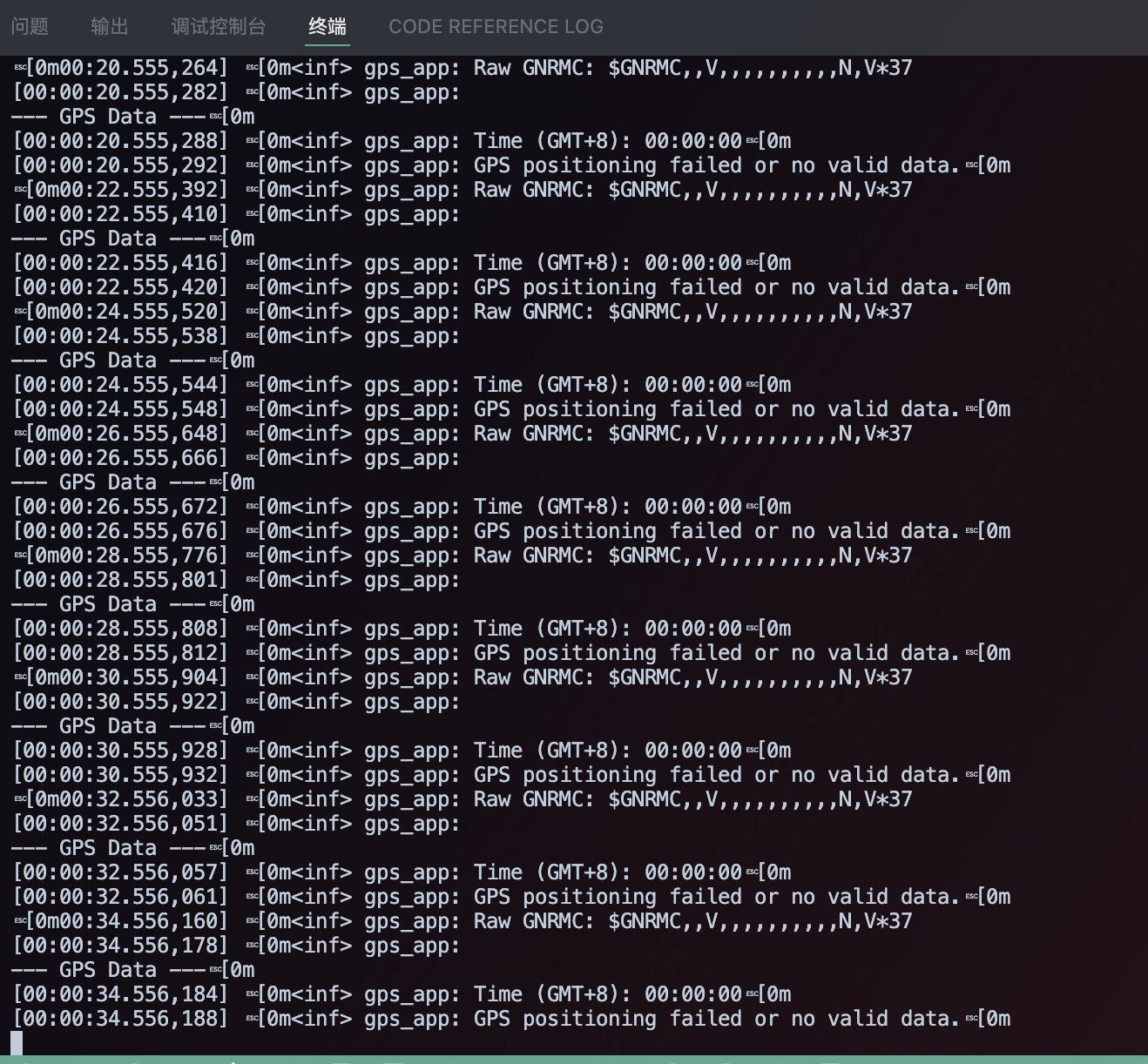
Si GPS.Status es 0, imprime un mensaje de "fallo en el posicionamiento".
-
Si no hay datos nuevos disponibles, imprime "No new GNRMC data available."
-
k_msleep(2000): El programa se detiene durante 2 segundos después de cada bucle para controlar la frecuencia de salida.
-
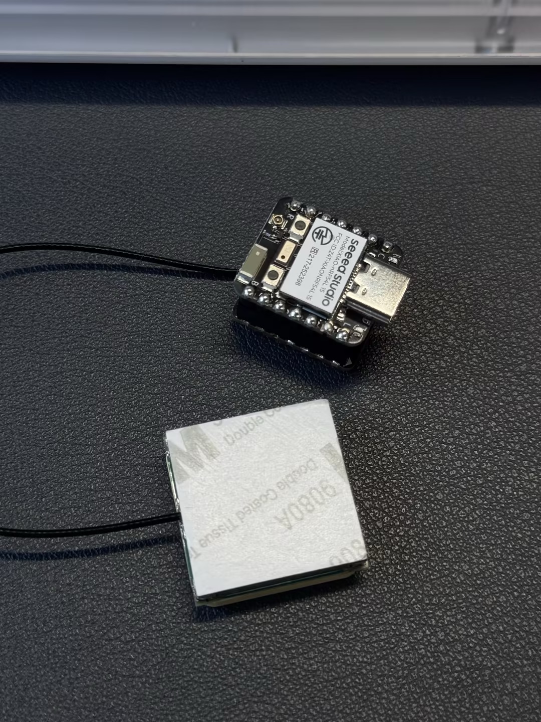
Gráfico de resultados
 |  |
I2C
Preparación de hardware
| Seeed Studio XIAO nRF54L15 Sense | Seeed Studio Expansion Board Base for XIAO |
|---|---|
| |
Implementación de software
#include <zephyr/kernel.h>
#include <zephyr/device.h>
#include <zephyr/display/cfb.h>
#include <stdio.h>
#include <string.h>
#define LOG_LEVEL CONFIG_LOG_DEFAULT_LEVEL
#include <zephyr/logging/log.h>
LOG_MODULE_REGISTER(main_app, LOG_LEVEL);
/**
* @brief Initializes the display device.
* @param[out] dev Pointer to the display device struct.
* @return 0 on success, -1 on failure.
*/
static int display_init(const struct device **dev) {
*dev = DEVICE_DT_GET(DT_CHOSEN(zephyr_display));
if (!device_is_ready(*dev)) {
LOG_ERR("Device %s not ready", (*dev)->name);
return -1;
}
if (display_set_pixel_format(*dev, PIXEL_FORMAT_MONO10) != 0) {
if (display_set_pixel_format(*dev, PIXEL_FORMAT_MONO01) != 0) {
LOG_ERR("Failed to set required pixel format");
return -1;
}
}
LOG_INF("Initialized %s", (*dev)->name);
return 0;
}
/**
* @brief Initializes the Compact Framebuffer (CFB) and display blanking.
* @param dev Pointer to the display device struct.
* @return 0 on success, -1 on failure.
*/
static int framebuffer_setup(const struct device *dev) {
if (cfb_framebuffer_init(dev)) {
LOG_ERR("Framebuffer initialization failed!");
return -1;
}
cfb_framebuffer_clear(dev, true);
display_blanking_off(dev);
return 0;
}
/**
* @brief Selects a suitable font for the display.
* @param dev Pointer to the display device struct.
* @param[out] font_width Pointer to store the width of the selected font.
* @param[out] font_height Pointer to store the height of the selected font.
* @return 0 on success, -1 if no suitable font is found.
*/
static int select_font(const struct device *dev, uint8_t *font_width, uint8_t *font_height) {
int chosen_font_idx = -1;
uint8_t current_font_width, current_font_height;
for (int idx = 0; idx < 42; idx++) {
if (cfb_get_font_size(dev, idx, ¤t_font_width, ¤t_font_height) == 0) {
if (current_font_width == 8 && current_font_height == 8) {
chosen_font_idx = idx;
*font_width = current_font_width;
*font_height = current_font_height;
cfb_framebuffer_set_font(dev, chosen_font_idx);
LOG_INF("Selected font idx: %d, width: %d, height: %d", chosen_font_idx, *font_width, *font_height);
break;
}
if (chosen_font_idx == -1 && current_font_width > 0 && current_font_height > 0) {
chosen_font_idx = idx;
*font_width = current_font_width;
*font_height = current_font_height;
cfb_framebuffer_set_font(dev, chosen_font_idx);
LOG_INF("Defaulting to font idx: %d, width: %d, height: %d", chosen_font_idx, *font_width, *font_height);
}
} else {
break;
}
}
if (chosen_font_idx == -1) {
LOG_ERR("No suitable font found or loaded!");
return -1;
}
return 0;
}
/**
* @brief Prints a single line of text at specified row and column.
* @param dev Pointer to the display device struct.
* @param text The string to print.
* @param row The row number (0-indexed) where the text should start.
* @param col The column number (0-indexed) where the text should start.
* @param font_width The width of the currently selected font in pixels.
* @param font_height The height of the currently selected font in pixels.
*/
static void print_text_by_row_col(const struct device *dev, const char *text, int row, int col,
uint8_t font_width, uint8_t font_height) {
int pixel_x = col * font_width;
int pixel_y = row * font_height;
if (cfb_print(dev, text, pixel_x, pixel_y)) {
LOG_ERR("Failed to print text: \"%s\" at row %d, col %d", text, row, col);
}
}
int main(void) {
const struct device *dev;
uint8_t font_width = 0;
uint8_t font_height = 0;
uint16_t x_res, y_res;
if (display_init(&dev) != 0) {
return 0;
}
if (framebuffer_setup(dev) != 0) {
return 0;
}
if (select_font(dev, &font_width, &font_height) != 0) {
return 0;
}
x_res = cfb_get_display_parameter(dev, CFB_DISPLAY_WIDTH);
y_res = cfb_get_display_parameter(dev, CFB_DISPLAY_HEIGHT);
LOG_INF("Display resolution: %dx%d", x_res, y_res);
cfb_set_kerning(dev, 0);
while (1) {
cfb_framebuffer_clear(dev, false);
const char *line1_text = "nRF54L15";
// Print line1 at row 1, column 2
print_text_by_row_col(dev, line1_text, 1, 2, font_width, font_height);
const char *line2_text = "Hello World";
// Print line2 at row 2, column 1
print_text_by_row_col(dev, line2_text, 2, 1, font_width, font_height);
cfb_framebuffer_finalize(dev);
k_sleep(K_MSEC(1000));
}
return 0;
}
Configuración e inicialización del dispositivo de visualización
-
Módulo de registro
main_app:- #define LOG_LEVEL CONFIG_LOG_DEFAULT_LEVEL y LOG_MODULE_REGISTER(main_app, LOG_LEVEL) registran un módulo de registro llamado main_app y establecen su nivel de registro en la configuración predeterminada del sistema. Esto permite a los desarrolladores depurar y mostrar información fácilmente a través del sistema de registro de Zephyr.
-
Función
display_init():-
*dev = DEVICE_DT_GET(DT_CHOSEN(zephyr_display));:Esta línea obtiene el dispositivo de visualización elegido desde el Device Tree de Zephyr. Este enfoque garantiza que el código sea independiente del hardware. -
display_set_pixel_format(*dev, PIXEL_FORMAT_MONO10):El código intenta configurar el formato de píxel de la pantalla a PIXEL_FORMAT_MONO10. Si esto falla, entonces intenta PIXEL_FORMAT_MONO01. Esto garantiza que la pantalla funcione en modo monocromo, lo cual es necesario para algunas tecnologías de visualización (por ejemplo, OLED o e-Paper).
-
-
Función
framebuffer_setup():-
cfb_framebuffer_init(dev):Esto inicializa el Compact Framebuffer (CFB). CFB es una biblioteca gráfica ligera en Zephyr utilizada para dibujar texto y gráficos simples en pantallas. -
cfb_framebuffer_clear(dev, true):Esto borra el framebuffer y escribe inmediatamente su contenido en la pantalla, garantizando una pantalla limpia. -
display_blanking_off(dev):Esto desactiva la función de blanking de la pantalla, que normalmente es una señal de que la pantalla está lista para recibir datos y mostrar una imagen.
-
-
Función
select_font():-
cfb_get_font_size():Esta función recorre las fuentes disponibles para encontrar una adecuada. -
El código prioriza una fuente de píxeles
8x8, ya que es una fuente pequeña común y fácil de leer. -
Si no se encuentra una fuente
8x8, selecciona la primera fuente disponible de tamaño distinto de cero como respaldo. -
cfb_framebuffer_set_font(dev, chosen_font_idx):Una vez que se encuentra una fuente adecuada, se establece como la fuente actual para el framebuffer.
-
-
Función
print_text_by_row_col():
-int pixel_x = col * font_width;y int pixel_y = row * font_height;: Esta función convierte las coordenadas de fila y columna del texto (en unidades de caracteres) a coordenadas de píxeles, haciendo que la posición del texto sea más intuitiva.
cfb_print():Esta es la función principal de la biblioteca CFB utilizada para imprimir texto en la ubicación de píxeles especificada.
Bucle principal
La lógica central del código se ejecuta dentro de un bucle infinito while (1):
-
Borrado de la pantalla:
cfb_framebuffer_clear(dev, false):Al comienzo de cada bucle, esto borra el framebuffer sin actualizar inmediatamente la pantalla. Esto permite dibujar varios elementos a la vez, evitando el parpadeo de la pantalla. -
Impresión de texto:
-
Se definen dos cadenas,
line1_textyline2_text. -
print_text_by_row_col(): La función personalizada se utiliza para imprimir estas dos líneas de texto en posiciones específicas de fila y columna en la pantalla. La primera línea se imprime en
(1, 2)y la segunda línea en(2, 1). -
Actualización de la pantalla:
cfb_framebuffer_finalize(dev): Esta función envía todos los comandos de dibujo pendientes desde el framebuffer a la pantalla de una sola vez, haciendo que todo el contenido aparezca simultáneamente. -
Retardo:
k_sleep(K_MSEC(1000)):Después de cada bucle, el programa se detiene durante 1000 milisegundos (1 segundo). Esto controla la frecuencia de actualización de la pantalla, lo cual es adecuado para aplicaciones que muestran información estática, como un reloj o datos de sensores, de manera estable.
-
Gráfico de resultado

SPI
Preparación de hardware
| Seeed Studio XIAO nRF54L15 Sense | ePaper Driver Board for Seeed Studio XIAO |
|---|---|
|  |
Implementación de software
#include <zephyr/kernel.h>
#include <zephyr/device.h>
#include <zephyr/drivers/display.h>
#include <lvgl.h>

#define LOG_LEVEL CONFIG_LOG_DEFAULT_LEVEL
#include <zephyr/logging/log.h>
LOG_MODULE_REGISTER(epaper_simple);

int main(void)
{
    // Get display device
    const struct device *display_dev = DEVICE_DT_GET(DT_CHOSEN(zephyr_display));
    if (!device_is_ready(display_dev)) {
        LOG_ERR("Display device not ready!");
        return 0;
    }
    LOG_INF("Display device ready.");

    // Initialize LVGL
    // Must be called before any LVGL object creation or operation
    lv_init();

    // Turn off display blanking (for ePaper, this usually triggers a full refresh to clear old content)
    if (display_blanking_off(display_dev)) {
        LOG_ERR("Failed to turn off display blanking!");
        return 0;
    }
    LOG_INF("Display blanking is off. Screen should be cleared by full refresh.");

    // Get the current active screen and set its background to white
    // This is also an LVGL-level "clear" operation to ensure the canvas is white
    lv_obj_t *scr = lv_scr_act();
    lv_obj_set_style_bg_color(scr, lv_color_white(), LV_STATE_DEFAULT);
    lv_obj_set_style_bg_opa(scr, LV_OPA_COVER, LV_STATE_DEFAULT);

    // Remove screen padding and scrollbar
    lv_obj_set_style_pad_all(scr, 0, LV_STATE_DEFAULT);
    lv_obj_set_scrollbar_mode(scr, LV_SCROLLBAR_MODE_OFF);


    // Get display width and height (for layout)
    lv_disp_t *disp = lv_disp_get_default();
    lv_coord_t width = lv_disp_get_hor_res(disp);
    lv_coord_t height = lv_disp_get_ver_res(disp);
    LOG_INF("Display width: %d, height: %d", width, height);


    // Create a centered panel
    lv_obj_t *panel = lv_obj_create(scr);
    lv_obj_set_size(panel, 300, 100);
    lv_obj_align(panel, LV_ALIGN_CENTER, 0, 0);

    // Set panel background to white, border to black for visibility
    lv_obj_set_style_bg_color(panel, lv_color_white(), LV_STATE_DEFAULT);
    lv_obj_set_style_border_color(panel, lv_color_black(), LV_STATE_DEFAULT);
    lv_obj_set_style_border_width(panel, 2, LV_STATE_DEFAULT);
    lv_obj_set_style_pad_all(panel, 10, LV_STATE_DEFAULT);


    // Add text to the panel
    lv_obj_t *label = lv_label_create(panel);
    lv_label_set_text(label, "HELLO EPAPER");

    // Set text color to black for visibility on white background
    lv_obj_set_style_text_color(label, lv_color_black(), LV_STATE_DEFAULT);
    lv_obj_set_style_text_font(label, &lv_font_montserrat_24, LV_STATE_DEFAULT);
    lv_obj_align(label, LV_ALIGN_CENTER, 0, 0);

    // Add a time label at the top right
    lv_obj_t *time_label = lv_label_create(scr);
    lv_label_set_text(time_label, "Time 07:21 PM");
    lv_obj_set_style_text_color(time_label, lv_color_black(), LV_STATE_DEFAULT);
    lv_obj_set_style_text_font(time_label, &lv_font_montserrat_18, LV_STATE_DEFAULT);
    lv_obj_align(time_label, LV_ALIGN_TOP_RIGHT, -20, 10);

    // Add a Zephyr logo at the top left
    lv_obj_t *zephyr_label = lv_label_create(scr);
    lv_label_set_text(zephyr_label, "Powered by Zephyr");
    lv_obj_set_style_text_color(zephyr_label, lv_color_black(), LV_STATE_DEFAULT);
    lv_obj_set_style_text_font(zephyr_label, &lv_font_montserrat_24, LV_STATE_DEFAULT);
    lv_obj_align(zephyr_label, LV_ALIGN_BOTTOM_LEFT, 20, -10);

    // Add author label at the bottom right
    lv_obj_t *author_label = lv_label_create(scr);
    lv_label_set_text(author_label, "Author: Stellar");
    lv_obj_set_style_text_color(author_label, lv_color_black(), LV_STATE_DEFAULT);
    lv_obj_set_style_text_font(author_label, &lv_font_montserrat_16, LV_STATE_DEFAULT);
    lv_obj_align(author_label, LV_ALIGN_BOTTOM_RIGHT, -20, -10);


    // Add four squares at the top left with a for loop
    lv_obj_t *squares[4];
    int square_offsets = 20;
    for (int i = 0; i < 4; i++) {
        squares[i] = lv_obj_create(scr);
        lv_obj_set_size(squares[i], 30, 30);
        lv_obj_set_style_bg_color(squares[i], lv_color_white(), LV_STATE_DEFAULT);
        lv_obj_set_style_border_color(squares[i], lv_color_black(), LV_STATE_DEFAULT);
        lv_obj_set_style_border_width(squares[i], 2, LV_STATE_DEFAULT);
        lv_obj_set_style_radius(squares[i], 0, LV_STATE_DEFAULT);
        lv_obj_align(squares[i], LV_ALIGN_TOP_LEFT, square_offsets, 20);
        square_offsets+=40;
    }

    while (1) {
        lv_task_handler();
        k_sleep(K_MSEC(1000)); // Lower refresh rate, suitable for ePaper
    }
    return 0;
}
Inicialización del dispositivo:
-
El código primero obtiene el dispositivo de pantalla desde el device tree usando
DEVICE_DT_GET(DT_CHOSEN(zephyr_display)). -
Luego llama a
device_is_ready()para comprobar si el dispositivo está correctamente inicializado y listo para funcionar. Este es un primer paso crucial para cualquier interacción con el hardware.
Inicialización de LVGL:
lv_init()es el punto de entrada para la biblioteca gráfica LVGL. Debe llamarse antes de que se creen cualquier objeto LVGL o se realice cualquier operación, ya que inicializa el estado interno de la biblioteca.
Limpieza de la pantalla:
-
Se llama a la función
display_blanking_off(). Para pantallas de tinta electrónica (E-Paper), esto normalmente desencadena una actualización completa para borrar cualquier contenido antiguo en la pantalla. -
Para garantizar aún más un lienzo limpio, el código usa
lv_scr_act()para obtener la pantalla activa actual y establece su color de fondo en blanco usandolv_obj_set_style_bg_color(), cubriendo toda el área de visualización.
Preparación del diseño de la pantalla:
-
Las funciones
lv_disp_get_hor_res()ylv_disp_get_ver_res()se utilizan para obtener el ancho y la altura reales de la pantalla, lo cual es útil para una colocación precisa de los elementos de la interfaz de usuario más adelante. -
El código también elimina el relleno de la pantalla
(lv_obj_set_style_pad_all())y la barra de desplazamiento(lv_obj_set_scrollbar_mode())para maximizar el área de dibujo utilizable.
Creación y configuración de elementos de la UI:
-
Panel: Se crea un objeto panel con
lv_obj_create(scr). Su tamaño y alineación centrada se establecen usandolv_obj_set_size()ylv_obj_align(). Su estilo, incluido el fondo blanco y el borde negro, se configura con funciones comolv_obj_set_style_bg_color()ylv_obj_set_style_border_color(). -
Etiquetas:
-
lv_label_create()se utiliza para crear etiquetas de texto. -
lv_label_set_text()establece el contenido de texto de las etiquetas. -
lv_obj_set_style_text_color()y lv_obj_set_style_text_font() se utilizan para establecer el color del texto y el tamaño de la fuente.
-
-
La función
lv_obj_align()coloca cada etiqueta en una ubicación específica en la pantalla, como el centro, la parte superior derecha, la parte inferior izquierda y la parte inferior derecha.
Cuadrados: Se utiliza un bucle for para crear cuatro pequeños objetos cuadrados. Su tamaño, estilo (relleno blanco con borde negro) y posición se establecen secuencialmente, organizándolos horizontalmente en la esquina superior izquierda de la pantalla.
Bucle principal:
-
The while(1)loop es la parte de ejecución continua del programa. -
lv_task_handler()se llama continuamente dentro del bucle para procesar todas las tareas internas de LVGL, como actualizar elementos de la UI y manejar eventos. -
k_sleep(K_MSEC(1000))pausa el hilo durante 1000 milisegundos. Para d estáticos
Gráfico de resultado

Soporte técnico y debate sobre el producto
Gracias por elegir nuestros productos. Estamos aquí para ofrecerte diferentes tipos de soporte y garantizar que tu experiencia con nuestros productos sea lo más fluida posible. Ofrecemos varios canales de comunicación para adaptarnos a diferentes preferencias y necesidades.