Multiplexación de pines con Seeed Studio XIAO nRF54LM20A Sense
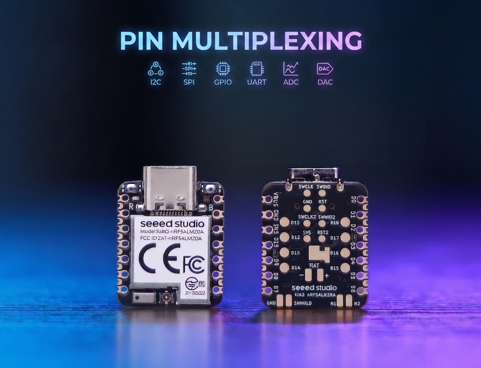
El XIAO nRF54LM20A cuenta con abundantes recursos de pines y admite de forma nativa el desarrollo con varias interfaces periféricas estándar, incluidas Digital, Analógica, SPI e IIC. Este artículo muestra implementaciones relevantes con casos de aplicación prácticos.
Este tutorial se desarrolla sobre el sistema de compilación PlatformIO y Zephyr RTOS. Si no estás familiarizado con la creación de un proyecto para el XIAO nRF54LM20A en PlatformIO, puedes ir a Getting Sarted With Seeed Studio XIAO nRF54LM20A Sense
Digital
Los pines digitales realizan principalmente el control de encendido y apagado de sensores y actuadores externos mediante la salida de niveles lógicos altos y bajos. Combinado con la placa de expansión Grove Base for XIAO y los módulos periféricos estándar Grove, esta sección detalla la lógica del controlador subyacente y los métodos prácticos de invocación de los pines digitales en el XIAO nRF54LM20A.
Preparación de hardware
| Seeed Studio XIAO nRF54LM20A Sense | Seeed Studio Grove Base for XIAO | Grove - Piezo Buzzer | Grove - Button |
|---|---|---|---|
 |  |  | |
Preparación de software
Según el pinout del XIAO nRF54LM20A, se puede seleccionar P1.0 como pin de control para el Grove-Button y P1.31 como pin de control para el Grove-Pizero Buzzer.
- Para el pinout del XIAO nRF54LM20A, haz clic en XIAO nRF54LM20A Pin List para ver los detalles.
Escribe el programa para main.c
/*
 * Grove Button (P1.0) + Grove Buzzer (P1.31) - Digital mode
 * Button pressed → Buzzer ON; Button released → Buzzer OFF
 *
 * NOTE: Requires an ACTIVE buzzer (built-in oscillator).
 *       A passive piezo buzzer needs PWM — use plan B instead.
 */

#include <zephyr/kernel.h>
#include <zephyr/device.h>
#include <zephyr/drivers/gpio.h>
#include <zephyr/sys/printk.h>

#define BUTTON_PIN 0  /* P1.0 - Grove Button - D0 */
#define BUZZER_PIN 31 /* P1.31 - Grove Buzzer - D1 */

int main(void)
{
	const struct device *gpio1_dev = DEVICE_DT_GET(DT_NODELABEL(gpio1));

	printk("=== Grove Button + Buzzer (Digital Mode) ===\n");

	if (!device_is_ready(gpio1_dev))
	{
		printk("ERROR: gpio1 device is not ready!\n");
		return -1;
	}
	printk("gpio1 device ready: %s\n", gpio1_dev->name);

	/* Grove Button has onboard pull-down; HIGH = pressed */
	gpio_pin_configure(gpio1_dev, BUTTON_PIN, GPIO_INPUT);

	/* Buzzer: HIGH = on */
	gpio_pin_configure(gpio1_dev, BUZZER_PIN, GPIO_OUTPUT_INACTIVE);

	printk("Button:  P1.%d (input)\n", BUTTON_PIN);
	printk("Buzzer:  P1.%d (output)\n", BUZZER_PIN);
	printk("Press the button to turn on the buzzer...\n");

	int last_val = 0;

	while (1)
	{
		int val = gpio_pin_get(gpio1_dev, BUTTON_PIN);
		if (val >= 0)
		{
			gpio_pin_set(gpio1_dev, BUZZER_PIN, val);

			/* Only print on state change to avoid log spam */
			if (val != last_val)
			{
				printk("Button %s → Buzzer %s\n",
				       val ? "PRESSED " : "released",
				       val ? "ON" : "OFF");
				last_val = val;
			}
		}
		k_msleep(10);
	}

	return 0;
}
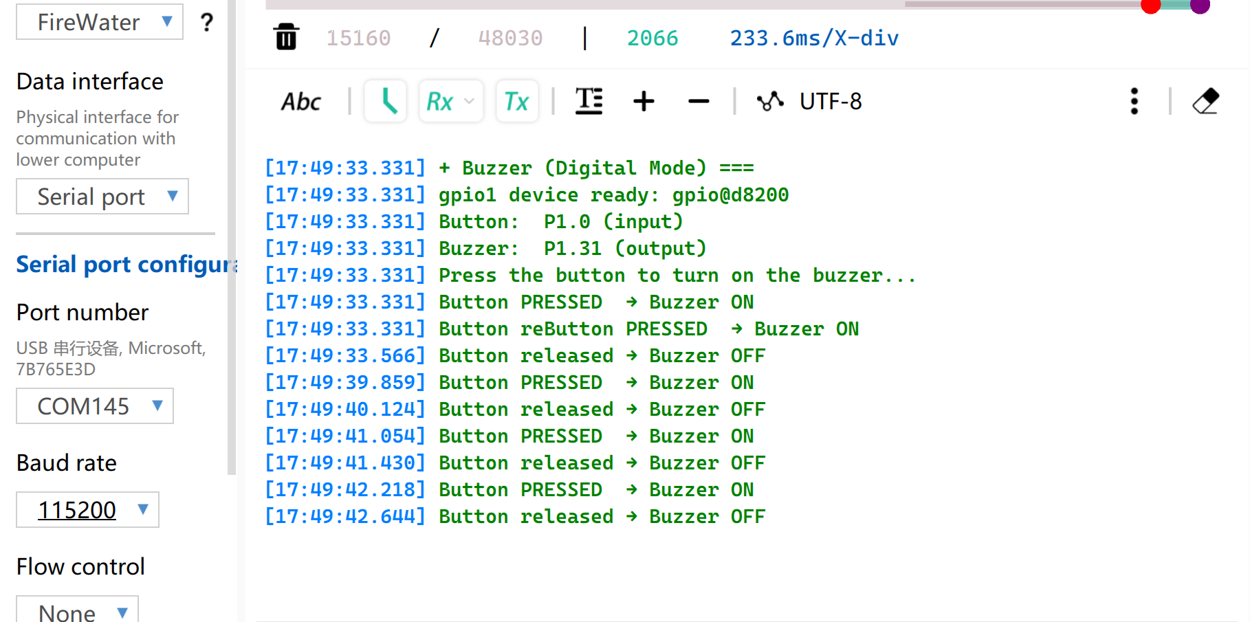
Resultado
Después de flashear el firmware, pulsa el botón y el zumbador emitirá un pitido. Y el puerto serie imprimirá el estado.
Ten en cuenta que debes configurar la velocidad en baudios a 115200. Si abres directamente Monitor en VS, se recomienda configurar la velocidad en baudios en el archivo .ini
PWM
PWM es una función de salida de forma de onda temporizada implementada sobre la base de GPIOs de salida digital. Cambia rápidamente los niveles de los pines a una frecuencia fija y ajusta dinámicamente el ciclo de trabajo del nivel alto dentro de un solo ciclo, para así enviar señales analógicas equivalentes a los periféricos. En aplicaciones de ingeniería práctica, PWM se utiliza ampliamente para el control preciso del ángulo de servomotores y el ajuste suave del brillo de los LED.
Preparación de hardware
| Seeed Studio XIAO nRF54LM20A Sense | Seeed Studio Grove Base for XIAO | Grove - Servo |
|---|---|---|
|  | |
Preparación de software
Según el pinout del XIAO nRF54LM20A, se puede seleccionar P1.0 como pin de control para el Grove-Servo.
- Para el pinout del XIAO nRF54LM20A, haz clic en XIAO nRF54LM20A Pin List para ver los detalles.
- Modifica el archivo del árbol de dispositivos
app.overlay. Para la función de salida PWM, la instancia de hardware debe estar vinculada explícitamente al nodopwm20,pwm21opwm22. La salida de consola UART predeterminada del sistema está asociada al nodouart20.
app.overlay
/*
 * UART20 (console) + PWM20 (servo) configuration for XIAO nRF54LM20A.
 *
 * Note: spi23 and uart20 share the same peripheral instance (0xc6000),
 * so only one can be active at a time. SD card via spi23 is removed here.
 */

/ {
	chosen {
		zephyr,console    = &uart20;
		nordic,rpc-uart   = &uart20;
		zephyr,shell-uart = &uart20;
	};
};

/* ── UART20 (console, TX: P1.11 / RX: P1.10) ── */
&uart20 {
	current-speed = <115200>;
	status = "okay";
};

&uart20_default {
	group1 {
		psels = <NRF_PSEL(UART_TX, 1, 11)>;
	};
	group2 {
		psels = <NRF_PSEL(UART_RX, 1, 10)>;
		bias-pull-up;
	};
};

&uart20_sleep {
	group1 {
		psels = <NRF_PSEL(UART_TX, 1, 11)>,
			<NRF_PSEL(UART_RX, 1, 10)>;
		low-power-enable;
	};
};

/* ── PWM20 (servo, P1.0) ── */
&pwm20 {
	status = "okay";
	pinctrl-0 = <&servo_pwm20_default>;
	pinctrl-1 = <&servo_pwm20_sleep>;
	pinctrl-names = "default", "sleep";
};

&pinctrl {
	servo_pwm20_default: servo_pwm20_default {
		group1 {
			psels = <NRF_PSEL(PWM_OUT0, 1, 0)>; /* P1.0 */
		};
	};
	servo_pwm20_sleep: servo_pwm20_sleep {
		group1 {
			psels = <NRF_PSEL(PWM_OUT0, 1, 0)>;
			low-power-enable;
		};
	};
};
- Modifica el archivo
prj.confpara habilitar las configuraciones PWM relevantes.
CONFIG_PWM=y
CONFIG_SERIAL=y
CONFIG_PRINTK=y
CONFIG_UART_CONSOLE=y
- Escribe el programa main.c para implementar la función de control del servo por PWM y configura parámetros como el período de PWM.
/*
 * Servo control on P1.0 via PWM (50 Hz).
 * Sweeps 0→180° at ~100°/s, then returns 180→0° at ~33°/s.
 * Current angle is printed to serial console.
 */

#include <zephyr/kernel.h>
#include <zephyr/device.h>
#include <zephyr/drivers/pwm.h>
#include <zephyr/sys/printk.h>

/* Standard servo: 50 Hz period, 0.5–2.5 ms pulse for 0–180° */
#define SERVO_PERIOD_NS PWM_MSEC(20)
#define SERVO_MIN_NS PWM_USEC(500)
#define SERVO_MAX_NS PWM_USEC(2500)

#define SERVO_CHANNEL 0

/* 10 ms/step → ~100°/s forward; 30 ms/step → ~33°/s return */
#define STEP_FWD_MS 30
#define STEP_RET_MS 30

static const struct device *pwm_dev = DEVICE_DT_GET(DT_NODELABEL(pwm20));

static int set_angle(int degrees)
{
    uint32_t pulse = SERVO_MIN_NS +
                     (uint32_t)((uint64_t)degrees *
                                (SERVO_MAX_NS - SERVO_MIN_NS) / 180U);
    return pwm_set(pwm_dev, SERVO_CHANNEL, SERVO_PERIOD_NS, pulse,
                   PWM_POLARITY_NORMAL);
}

int main(void)
{
    printk("=== boot ===\n");

    if (!device_is_ready(pwm_dev))
    {
        printk("Error: PWM device not ready\n");
        return -1;
    }

    printk("Servo control started on P1.0\n");

    while (1)
    {
        /* 0° → 180° (faster) */
        for (int a = 0; a <= 180; a++)
        {
            if (set_angle(a) != 0)
            {
                printk("PWM error at %d deg\n", a);
            }
            else
            {
                printk("Angle: %d deg\n", a);
            }
            k_msleep(STEP_FWD_MS);
        }

        /* 180° → 0° (slower) */
        for (int a = 180; a >= 0; a--)
        {
            if (set_angle(a) != 0)
            {
                printk("PWM error at %d deg\n", a);
            }
            else
            {
                printk("Angle: %d deg\n", a);
            }
            k_msleep(STEP_RET_MS);
        }
    }

    return 0;
}
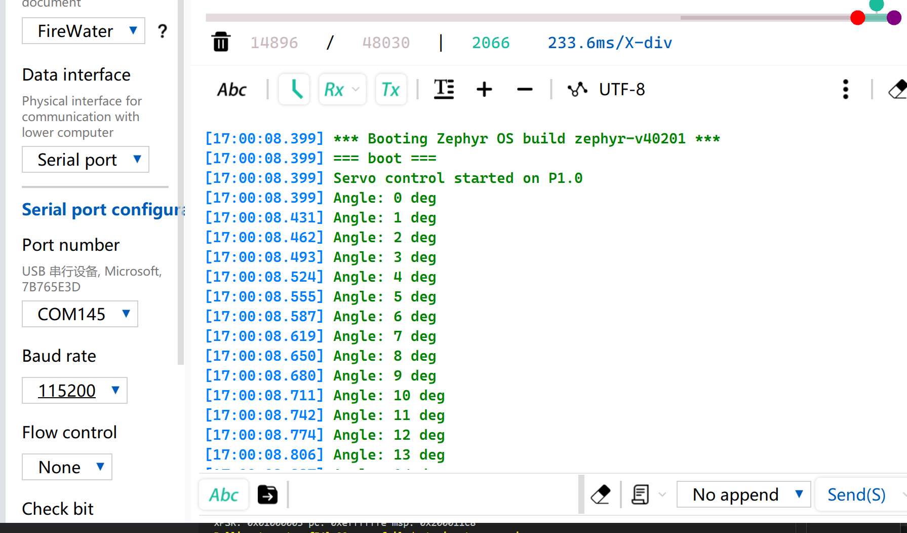
Resultado
Después de flashear el firmware, el servo gira de 0° a 180° a una velocidad de 33 radianes por segundo y luego vuelve a girar hasta 0°.
Mientras tanto, el ángulo actual del servo se imprimirá a través del puerto serie USB.
Analógico
La E/S analógica se basa en un Convertidor Analógico-Digital (ADC) y se utiliza principalmente para capturar señales de voltaje analógicas continuas emitidas por sensores externos. Después de obtener los valores de muestreo digitales sin procesar (Raw Data), se pueden mapear a valores reales de medición de ingeniería utilizando algoritmos de conversión lineales o no lineales específicos. Esta función se utiliza ampliamente en escenarios como el muestreo de voltaje de batería y la monitorización en tiempo real de magnitudes físicas, incluyendo la humedad del suelo y la temperatura ambiente.
Preparación de hardware
| Seeed Studio XIAO nRF54LM20A Sense | Seeed Studio Grove Base for XIAO | Grove - Capacitive Soil Moisture Sensor |
|---|---|---|
|  | |
Preparación de software
De acuerdo con el pinout del XIAO nRF54LM20A, configura P1.00 como el pin de salida PWM.
- Para el pinout del XIAO nRF54LM20A, haz clic en XIAO nRF54LM20A Pin List para ver los detalles.
- Modifica el archivo del device tree. El pin P1.00 corresponde al canal 0 del ADC y debe vincularse al nodo del device tree.
/*
 * UART20 (console) + ADC channel 0 (P1.0 / AIN0) for XIAO nRF54LM20A.
 */

/ {
	chosen {
		zephyr,console    = &uart20;
		nordic,rpc-uart   = &uart20;
		zephyr,shell-uart = &uart20;
	};

	zephyr,user {
		io-channels = <&adc 0>;
	};
};


/* ── UART20 (console, TX: P1.11 / RX: P1.10) ── */
&uart20 {
	current-speed = <115200>;
	status = "okay";
};

&uart20_default {
	group1 {
		psels = <NRF_PSEL(UART_TX, 1, 11)>;
	};
	group2 {
		psels = <NRF_PSEL(UART_RX, 1, 10)>;
		bias-pull-up;
	};
};

&uart20_sleep {
	group1 {
		psels = <NRF_PSEL(UART_TX, 1, 11)>,
			<NRF_PSEL(UART_RX, 1, 10)>;
		low-power-enable;
	};
};
- Modifica el archivo
prj.confpara habilitar las configuraciones relacionadas con el ADC.
CONFIG_ADC=y
CONFIG_ADC_NRFX_SAADC=y
CONFIG_SERIAL=y
CONFIG_PRINTK=y
CONFIG_UART_CONSOLE=y
- Escribe el programa main.c, utiliza el pin P1.00 como pin de entrada analógica y envía el valor leído a través del puerto serie USB cada 500 ms.
/*
 * Read ADC on P1.0 (AIN0, channel 0) and print raw value every 500 ms.
 */

#include <zephyr/kernel.h>
#include <zephyr/drivers/adc.h>
#include <zephyr/sys/printk.h>

static const struct adc_dt_spec adc_ch =
    ADC_DT_SPEC_GET(DT_PATH(zephyr_user));

int main(void)
{
    int ret;

    if (!adc_is_ready_dt(&adc_ch))
    {
        printk("ADC not ready\n");
        return -1;
    }

    ret = adc_channel_setup_dt(&adc_ch);
    if (ret < 0)
    {
        printk("ADC channel setup failed: %d\n", ret);
        return ret;
    }

    int16_t buf;
    struct adc_sequence seq = {
        .buffer = &buf,
        .buffer_size = sizeof(buf),
    };
    adc_sequence_init_dt(&adc_ch, &seq);

    while (1)
    {
        ret = adc_read_dt(&adc_ch, &seq);
        if (ret < 0)
        {
            printk("ADC read error: %d\n", ret);
        }
        else
        {
            printk("ADC raw: %d\n", buf);
        }
        k_msleep(500);
    }

    return 0;
}
Resultado
Después de flashear el programa, inserta el Grove-Capacitive Soil Moisture Sensor en plantas en maceta domésticas.
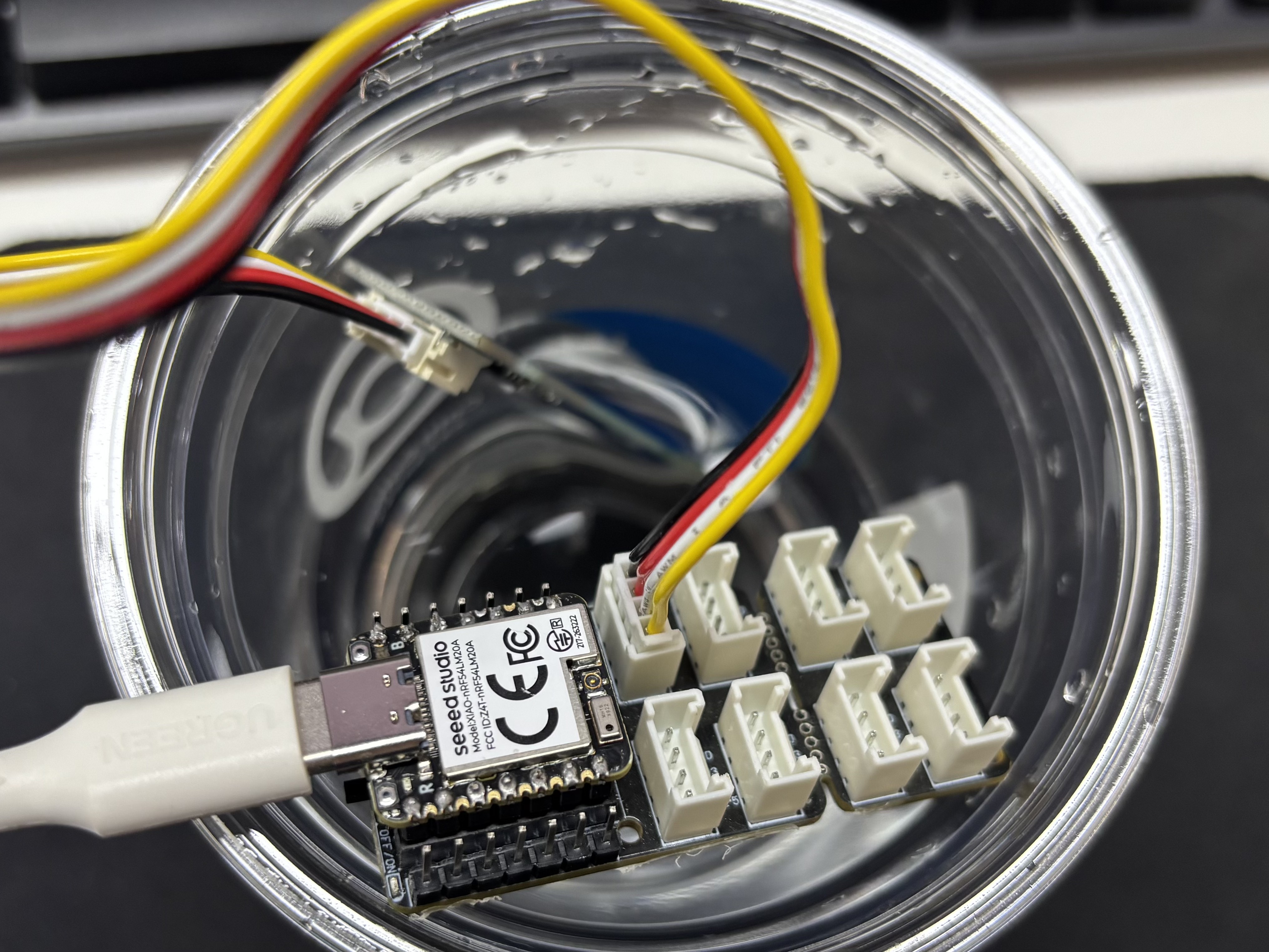
Abre el asistente de puerto serie en tu ordenador y observa los valores de salida.
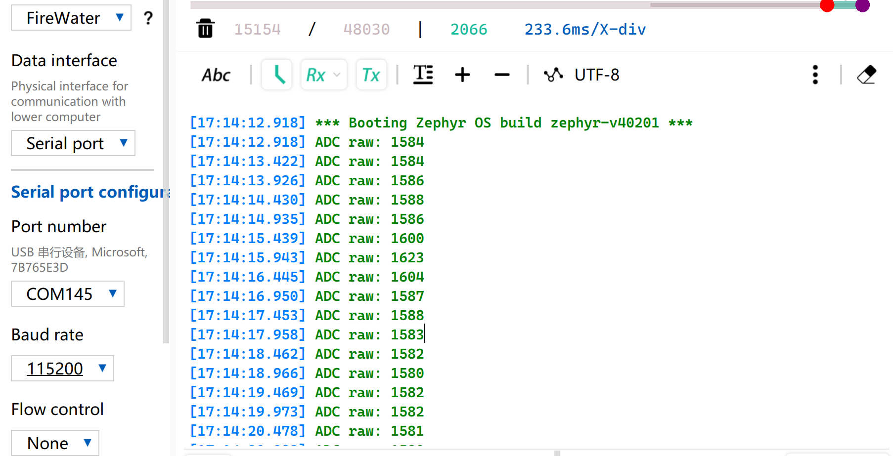
Tabla de referencia de lectura de voltaje
| Estado | Voltaje de salida del sensor | Valor bruto esperado del ADC |
|---|---|---|
| En el aire (seco) | ~2.0–2.4V | ~3400–4095 |
| En suelo húmedo | ~1.3–1.8V | ~2200–3000 |
| Totalmente sumergido en agua | ~0.8–1.2V | ~1365–2048 |
Debido a las diferencias individuales de los componentes, las mediciones de diferentes módulos en el mismo entorno pueden variar.
UART
El Receptor/Transmisor Asíncrono Universal (UART) es un protocolo estándar de comunicación serie asíncrona. No requiere señales de reloj externas para la sincronización y realiza la transmisión y recepción de datos de forma asíncrona basándose en la velocidad en baudios preestablecida por ambas partes de la comunicación. En cuanto al cableado físico, se puede establecer un enlace de datos full-dúplex simplemente cruzando los pines TX y RX de los dispositivos y conectando sus tierras entre sí. Con un coste de hardware mínimo y compatibilidad con el envío y la recepción simultáneos, UART se adopta ampliamente en sistemas embebidos para la salida de registros de consola, la depuración de periféricos modulares y la comunicación de datos punto a punto de bajo ancho de banda.
Preparación de hardware
| Seeed Studio XIAO nRF54LM20A Sense | USB to TTL Converter |
|---|---|
 | |
Preparación de software
Según la distribución de pines de XIAO nRF54LM20A, P1.08 y P1.09 se pueden seleccionar respectivamente como pines TX y RX para la comunicación serie.
- Para la distribución de pines de XIAO nRF54LM20A, haz clic en XIAO nRF54LM20A Pin List para ver los detalles.
- Modifica el archivo del árbol de dispositivos, asigna el pin P1.08 como UART TX y P1.09 como UART RX al nodo
uart21, y establece la velocidad en baudios del puerto serie en 115200.
/*
 * UART21 Demo - Device Tree Overlay for XIAO nRF54LM20A
 * UART21: TX=P1.8, RX=P1.9
 *
 * Note: The pinctrl configuration is already defined in the board file.
 * This overlay enables UART21 and sets it as disabled for the default console
 * so it can be used as a general-purpose serial port.
 */

/* UART21 is already configured in the board dts, just make sure it's enabled */
&uart20 {
	current-speed = <115200>;
	status = "okay";
};

/* UART21 is already configured in the board dts, just make sure it's enabled */
&uart21 {
	current-speed = <115200>;
	status = "okay";
};
- Modifica el archivo de configuración
prj.confpara habilitar las configuraciones UART relevantes.
# Serial and UART
CONFIG_SERIAL=y
# This demo uses uart_poll_in()/uart_poll_out().
# On nrfx UARTE, enabling async mode for the instance makes uart_poll_in()
# return -ENOTSUP, which breaks RX on uart21.

# Console (for logging via UART20)
CONFIG_CONSOLE=y
CONFIG_UART_CONSOLE=y

# Logging
CONFIG_LOG=y
CONFIG_LOG_BACKEND_UART=y
CONFIG_LOG_DEFAULT_LEVEL=3
- Escribe la función principal. Cuando se presione el botón BOOT integrado, el estado del puerto serie y la configuración de pines se imprimirán en el ordenador a través del puerto serie; de lo contrario, se imprimirá por defecto el estado de funcionamiento.
main.c
/*
 * UART21 Demo for XIAO nRF54LM20A (Polling Mode)
 *
 * This demo shows how to use UART21 for serial communication using polling mode.
 * - TX: P1.08
 * - RX: P1.09
 * - Baud rate: 115200
 *
 * The demo will:
 * 1. Send a welcome message on startup
 * 2. Echo back any received characters
 * 3. Periodically send a heartbeat message
 */

#include <zephyr/kernel.h>
#include <zephyr/device.h>
#include <zephyr/drivers/uart.h>
#include <zephyr/logging/log.h>
#include <stdio.h>
#include <string.h>

LOG_MODULE_REGISTER(uart21_demo, LOG_LEVEL_INF);

/* UART21 device */
static const struct device *uart21_dev = DEVICE_DT_GET(DT_NODELABEL(uart21));

#define RX_BUF_SIZE 128
#define TX_BUF_SIZE 256
#define HEARTBEAT_INTERVAL_MS 5000

static uint8_t rx_buf[RX_BUF_SIZE];
static size_t rx_buf_pos = 0;
static char tx_buf[TX_BUF_SIZE];

/* Send a string over UART21 using polling */
static void uart21_send_string(const char *str)
{
	while (*str)
	{
		uart_poll_out(uart21_dev, *str++);
	}
}

/* Receive a character from UART21 (non-blocking) */
static int uart21_recv_char(uint8_t *c)
{
	return uart_poll_in(uart21_dev, c);
}

static void handle_complete_line(void)
{
	rx_buf[rx_buf_pos] = '\0';

	if (rx_buf_pos > 0)
	{
		LOG_INF("Received: %s", rx_buf);
		uart21_send_string("\r\nYou sent: ");
		uart21_send_string((const char *)rx_buf);
	}

	uart21_send_string("\r\n");
	rx_buf_pos = 0;
	memset(rx_buf, 0, sizeof(rx_buf));
}

/* Process a received byte and maintain a simple line buffer */
static void process_rx_byte(uint8_t c)
{
	static bool last_was_cr;

	if (c == '\r' || c == '\n')
	{
		if (c == '\n' && last_was_cr)
		{
			last_was_cr = false;
			return;
		}

		uart21_send_string("\r\n");
		handle_complete_line();
		last_was_cr = (c == '\r');
		return;
	}

	last_was_cr = false;
	uart_poll_out(uart21_dev, c);

	if (rx_buf_pos < RX_BUF_SIZE - 1)
	{
		rx_buf[rx_buf_pos++] = c;
		return;
	}

	uart21_send_string("\r\n[Warning] Input too long, buffer cleared.\r\n");
	rx_buf_pos = 0;
	memset(rx_buf, 0, sizeof(rx_buf));
}

int main(void)
{
	uint8_t c;
	uint32_t heartbeat_count = 0;
	int64_t last_heartbeat = 0;

	LOG_INF("========================================");
	LOG_INF("  UART21 Demo for XIAO nRF54LM20A");
	LOG_INF("========================================");
	LOG_INF("");

	/* Check if UART21 device is ready */
	if (!device_is_ready(uart21_dev))
	{
		LOG_ERR("UART21 device not ready!");
		return -1;
	}
	LOG_INF("UART21 device ready: %s", uart21_dev->name);

	/* Send welcome message */
	uart21_send_string("\r\n");
	uart21_send_string("========================================\r\n");
	uart21_send_string("  UART21 Demo for XIAO nRF54LM20A\r\n");
	uart21_send_string("========================================\r\n");
	uart21_send_string("\r\n");
	uart21_send_string("Pin Configuration:\r\n");
	uart21_send_string("  TX: P1.08\r\n");
	uart21_send_string("  RX: P1.09\r\n");
	uart21_send_string("  Baud Rate: 115200\r\n");
	uart21_send_string("\r\n");
	uart21_send_string("Type something and press Enter to see it echoed.\r\n");
	uart21_send_string("\r\n");

	LOG_INF("UART21 demo started. Waiting for data...");
	LOG_INF("Connect UART terminal to P1.8(TX) and P1.9(RX)");

	last_heartbeat = k_uptime_get();

	/* Main loop */
	while (1)
	{
		/* Check for received data */
		if (uart21_recv_char(&c) == 0)
		{
			process_rx_byte(c);
		}

		/* Check for heartbeat */
		int64_t now = k_uptime_get();
		if (now - last_heartbeat >= HEARTBEAT_INTERVAL_MS)
		{
			last_heartbeat = now;
			heartbeat_count++;

			snprintf(tx_buf, sizeof(tx_buf),
					 "\r\n[Heartbeat #%u] UART21 running...\r\n",
					 heartbeat_count);
			uart21_send_string(tx_buf);

			LOG_INF("Heartbeat #%u sent", heartbeat_count);
		}

		/* Small delay to prevent busy loop */
		k_msleep(10);
	}

	return 0;
}
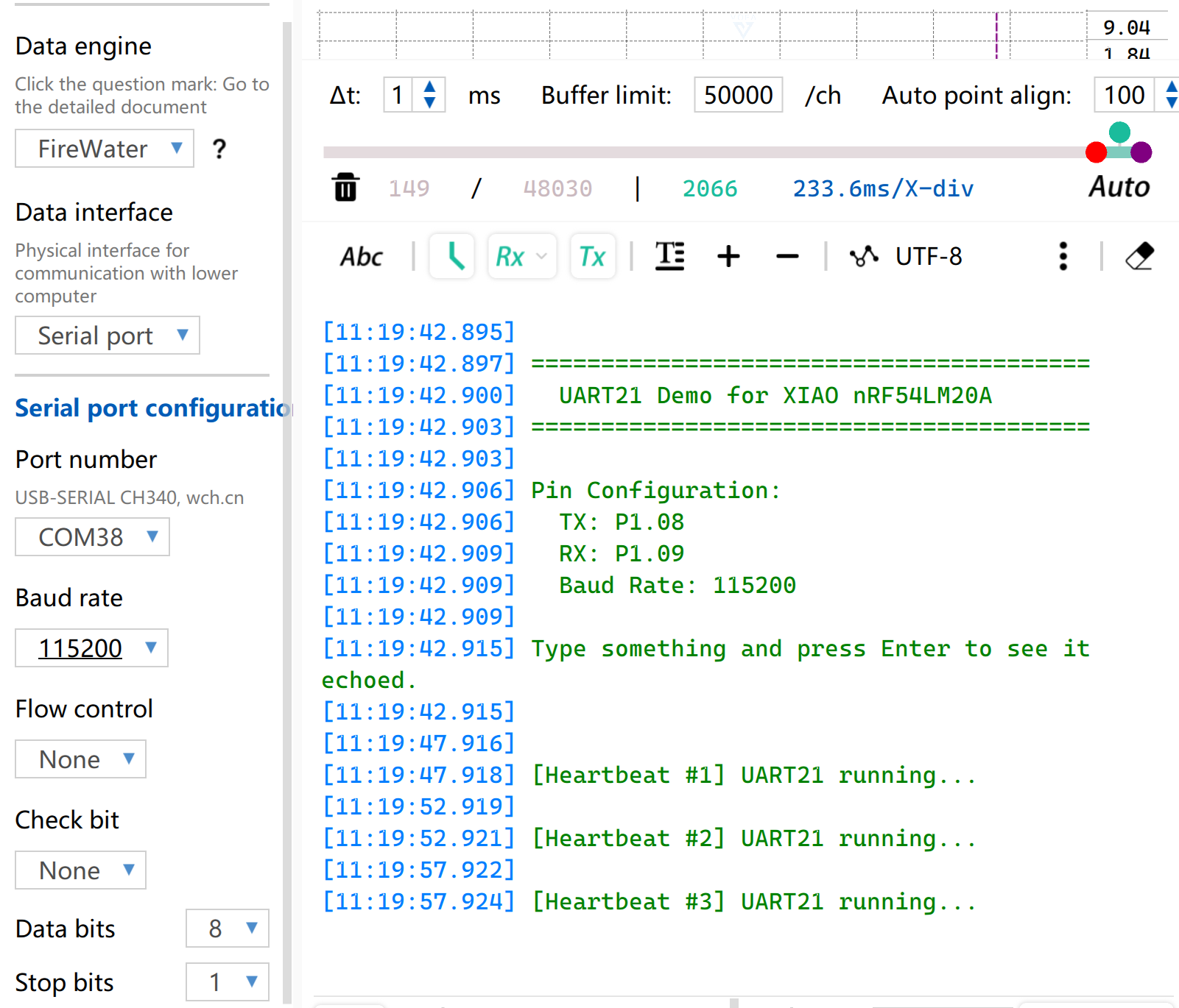
Resultado
- Cablea de acuerdo con el orden de la tabla
| XIAO nRF54LM20A | CH340 |
|---|---|
| VBUS | 5V |
| GND | GND |
| P1.08 - TX | RX |
| P1.09 - RX | TX |
- Abre el software de monitorización de puerto serie en tu ordenador. Cuando se presione el botón BOOT integrado, la información configurada del puerto serie se imprimirá a través del puerto serie. De forma predeterminada, se imprimirá la cadena
[Heartbeat # number] UART21 running....
I2C
I2C es un protocolo de comunicación de datos síncrono y half-dúplex. Permite la conexión de múltiples dispositivos mediante direccionamiento a través de la línea de reloj SCL y la línea de datos SDA, y se utiliza comúnmente para leer datos de sensores que requieren tasas de transmisión relativamente altas, como IMU y sensores de temperatura/humedad, o para la salida de pantalla OLED.
Preparación de hardware
| Seeed Studio XIAO nRF54LM20A Sense | Placa base de expansión Seeed Studio para XIAO |
|---|---|
 | |
Preparación de software
Según la distribución de pines de XIAO nRF54LM20A, P1.03 y P1.07 se pueden configurar como pines I2C.
- Para la distribución de pines de XIAO nRF54LM20A, haz clic en XIAO nRF54LM20A Pin List para ver los detalles.
- Modifica el árbol de dispositivos, configura P1.03 y P1.07 en XIAO nRF54LM20A como los pines del nodo
i2c22del árbol de dispositivos respectivamente, y luego añade el nodo del árbol de dispositivos para la pantalla. La pantalla OLED tiene una resolución de 128×64 y adopta el chip controlador común SSD1306.
/ {
        chosen {
                zephyr,display = &ssd1306_128x64;
        };
};

&i2c22 {
        status = "okay";
        zephyr,concat-buf-size = <2048>;
        ssd1306_128x64: ssd1306@3c {
                compatible = "solomon,ssd1306fb";
                reg = <0x3c>;
                width = <128>;
                height = <64>;
                segment-offset = <0>;
                page-offset = <0>;
                display-offset = <0>;
                multiplex-ratio = <63>;
                segment-remap;
                com-invdir;
                prechargep = <0x22>;
        };
};
- Modifica el archivo
prj.confpara habilitar las configuraciones relacionadas con I2C y la pantalla.
CONFIG_STDOUT_CONSOLE=y
CONFIG_HEAP_MEM_POOL_SIZE=16384
CONFIG_I2C=y
CONFIG_DISPLAY=y
CONFIG_SSD1306=y
CONFIG_LOG=y
CONFIG_LOG_DEFAULT_LEVEL=4
CONFIG_CHARACTER_FRAMEBUFFER=y
- Escribe la función principal para establecer la posición de visualización y las funciones para la cadena.
main.c
#include <zephyr/kernel.h>
#include <zephyr/device.h>
#include <zephyr/display/cfb.h>
#include <stdio.h>
#include <string.h>
#define LOG_LEVEL CONFIG_LOG_DEFAULT_LEVEL
#include <zephyr/logging/log.h>
LOG_MODULE_REGISTER(main_app, LOG_LEVEL);
#define CFB_MAX_FONT_INDEX 42
/* Display content */
#define LINE1_TEXT "Hello XIAO"
#define LINE2_TEXT "nRF54LM20A"
#define TOTAL_LINES 2
static int display_init(const struct device **dev) {
*dev = DEVICE_DT_GET(DT_CHOSEN(zephyr_display));
if (!device_is_ready(*dev)) {
LOG_ERR("Device %s not ready", (*dev)->name);
return -1;
}
if (display_set_pixel_format(*dev, PIXEL_FORMAT_MONO10) != 0) {
if (display_set_pixel_format(*dev, PIXEL_FORMAT_MONO01) != 0) {
LOG_ERR("Failed to set required pixel format");
return -1;
}
}
LOG_INF("Initialized %s", (*dev)->name);
return 0;
}
static int framebuffer_setup(const struct device *dev) {
if (cfb_framebuffer_init(dev)) {
LOG_ERR("Framebuffer initialization failed!");
return -1;
}
cfb_framebuffer_clear(dev, false);
display_blanking_off(dev);
return 0;
}
static int select_font(const struct device *dev, uint8_t *font_width, uint8_t *font_height) {
int chosen_font_idx = -1;
uint8_t current_font_width, current_font_height;
for (int idx = 0; idx < CFB_MAX_FONT_INDEX; idx++) {
if (cfb_get_font_size(dev, idx, ¤t_font_width, ¤t_font_height) != 0) {
continue;
}
if (current_font_width == 0 || current_font_height == 0) {
continue;
}
if (current_font_width == 8 && current_font_height == 8) {
chosen_font_idx = idx;
*font_width = current_font_width;
*font_height = current_font_height;
cfb_framebuffer_set_font(dev, chosen_font_idx);
LOG_INF("Selected 8x8 font idx: %d", chosen_font_idx);
break;
}
if (chosen_font_idx == -1) {
chosen_font_idx = idx;
*font_width = current_font_width;
*font_height = current_font_height;
cfb_framebuffer_set_font(dev, chosen_font_idx);
LOG_INF("Fallback font idx: %d, size: %dx%d",
chosen_font_idx, *font_width, *font_height);
}
}
if (chosen_font_idx == -1) {
LOG_ERR("No suitable font found!");
return -1;
}
return 0;
}
/**
* @brief Print a line of text centered on the display
* @param dev Display device
* @param text String to be printed
* @param line_index Index of current line (0-indexed)
* @param total_lines Total number of lines (for vertical centering calculation)
* @param font_width Font width in pixels
* @param font_height Font height in pixels
* @param x_res Horizontal resolution of the display
* @param y_res Vertical resolution of the display
*/
static void print_text_centered(const struct device *dev,
const char *text,
int line_index,
int total_lines,
uint8_t font_width,
uint8_t font_height,
uint16_t x_res,
uint16_t y_res)
{
int text_len = (int)strlen(text);
/* Horizontal center: (screen width - total text pixel width) / 2 */
int pixel_x = (x_res - text_len * font_width) / 2;
/* Vertical center: calculate total block height first, then offset current line */
int block_height = total_lines * font_height;
int pixel_y = (y_res - block_height) / 2 + line_index * font_height;
/* Prevent coordinate out-of-bounds */
if (pixel_x < 0) pixel_x = 0;
if (pixel_y < 0) pixel_y = 0;
if (cfb_print(dev, text, pixel_x, pixel_y)) {
LOG_ERR("Failed to print \"%s\" at (%d, %d)", text, pixel_x, pixel_y);
}
LOG_DBG("Print \"%s\" at pixel (%d, %d)", text, pixel_x, pixel_y);
}
int main(void) {
const struct device *dev;
uint8_t font_width = 0;
uint8_t font_height = 0;
if (display_init(&dev) != 0) return 0;
if (framebuffer_setup(dev) != 0) return 0;
if (select_font(dev, &font_width, &font_height) != 0) return 0;
uint16_t x_res = cfb_get_display_parameter(dev, CFB_DISPLAY_WIDTH);
uint16_t y_res = cfb_get_display_parameter(dev, CFB_DISPLAY_HEIGHT);
LOG_INF("Display resolution: %dx%d", x_res, y_res);
cfb_set_kerning(dev, 0);
while (1) {
cfb_framebuffer_clear(dev, false);
print_text_centered(dev, LINE1_TEXT, 0, TOTAL_LINES,
font_width, font_height, x_res, y_res);
print_text_centered(dev, LINE2_TEXT, 1, TOTAL_LINES,
font_width, font_height, x_res, y_res);
cfb_framebuffer_finalize(dev);
k_sleep(K_MSEC(1000));
}
return 0;
}
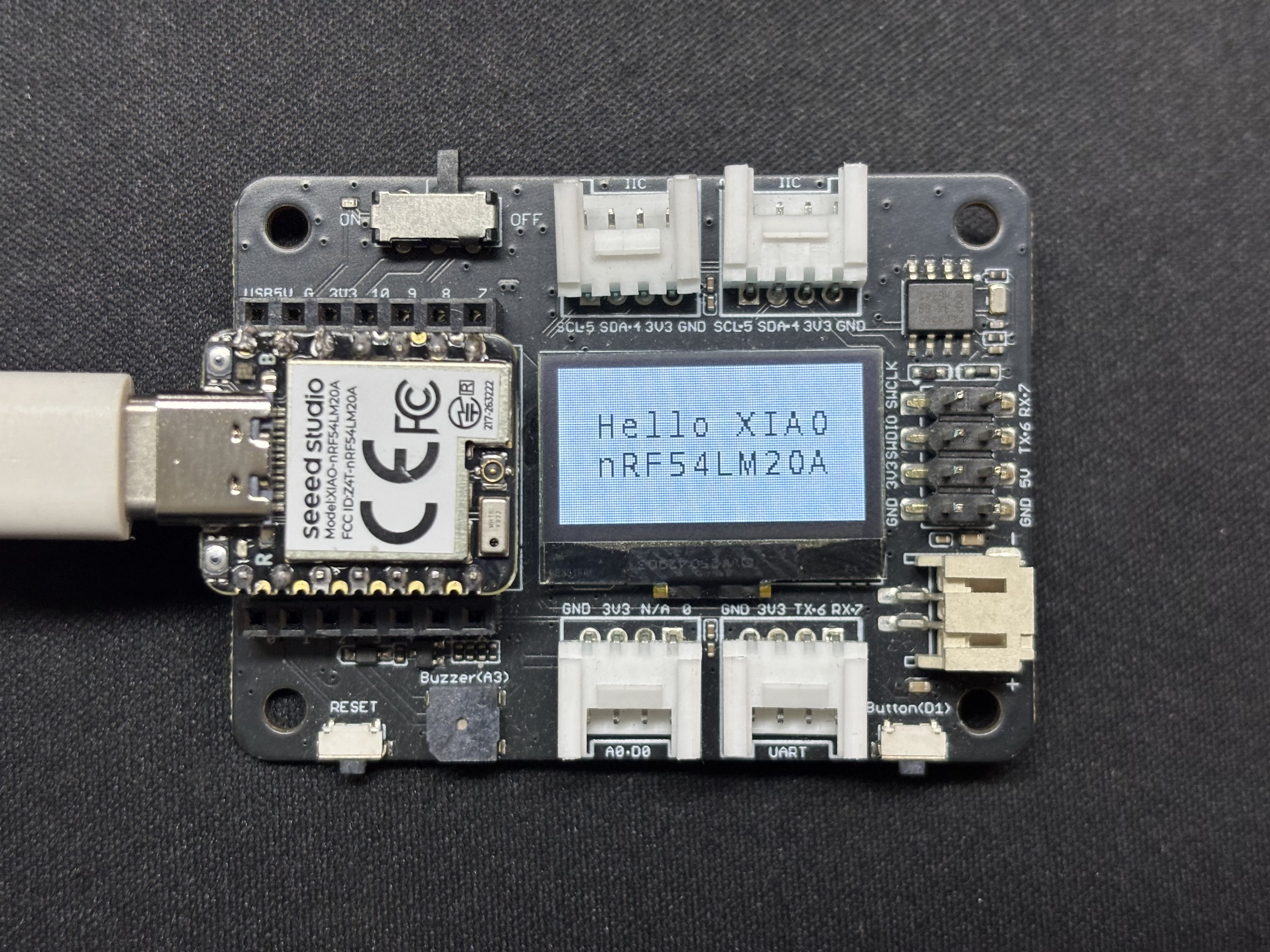
Resultado
Después de que el programa se ejecute, el texto Hello XIAO nRF54LM20A se mostrará en la pantalla y los datos del hilo se imprimirán a través del puerto serie USB.
SPI
SPI es un protocolo de comunicación síncrono, full-dúplex y de alta velocidad. A diferencia de la comunicación asíncrona, SPI se basa en una línea de reloj SCLK dedicada para una sincronización de datos precisa. Generalmente adopta la topología de hardware clásica de cuatro hilos que consta de los pines MOSI, MISO y de selección de chip CS/SS. Equipado con canales independientes de envío y recepción de datos y una alta frecuencia de reloj de bus, SPI ofrece un rendimiento excelente de transferencia de datos. Se utiliza ampliamente en escenarios de control de periféricos que requieren un gran ancho de banda, como dispositivos de almacenamiento masivo, incluidos Flash y tarjetas SD, pantallas de alta resolución y alta frecuencia de actualización, y sensores de muestreo de alta frecuencia.
Preparación de hardware
| Seeed Studio XIAO nRF54LM20A Sense | Pantalla redonda para Seeed Studio XIAO |
|---|---|
 | |
Preparación de software
- Para el pinout del XIAO nRF54LM20A, haz clic en XIAO nRF54LM20A Pin List para ver los detalles.
- Modifica el archivo del árbol de dispositivos. Para controlar la pantalla LCD, habilita el nodo spi23 y configura la asignación de pines en el árbol de dispositivos. Establece P1.04, P1.05 y P1.06 como SCK, MISO y MOSI de SPI respectivamente. Al mismo tiempo, configura P1.31 y P1.29 como los pines de control CS (Chip Select) y DC (Data/Command) de la pantalla.
app.overlay
#include <dt-bindings/pinctrl/nrf-pinctrl.h>
#include <zephyr/dt-bindings/gpio/gpio.h>
#include <zephyr/dt-bindings/display/panel.h>

/*
 * GC9X01X 240x240 round LCD configuration for XIAO nRF54LM20A
 * SPI23:  SCK=P1.04  MOSI=P1.06  MISO=P1.05
 * CS:     P1.31  (SPI bus software CS)
 * DC:     P1.29  (Data/Command select, on MIPI DBI node)
 *
 * In Zephyr 4.x the GC9X01X driver uses the MIPI DBI interface.
 * The display node must be a child of a zephyr,mipi-dbi-spi node,
 * which references the SPI controller via spi-dev phandle.
 */

/ {
    chosen {
        zephyr,console    = &uart20;
        nordic,rpc-uart   = &uart20;
        zephyr,shell-uart = &uart20;
        zephyr,display    = &gc9x01x;
    };

    mipi_dbi {
        compatible = "zephyr,mipi-dbi-spi";
        spi-dev = <&spi23>;
        dc-gpios = <&gpio1 29 GPIO_ACTIVE_HIGH>;
        write-only;
        #address-cells = <1>;
        #size-cells = <0>;

        gc9x01x: gc9x01x@0 {
            compatible = "galaxycore,gc9x01x";
            reg = <0>;
            mipi-max-frequency = <40000000>;
            pixel-format = <PANEL_PIXEL_FORMAT_RGB_565>;
            display-inversion;
            width  = <240>;
            height = <240>;
            status = "okay";
        };
    };
};

&spi23 {
    compatible = "nordic,nrf-spim";
    pinctrl-names = "default", "sleep";
    pinctrl-0 = <&spi23_default>;
    pinctrl-1 = <&spi23_sleep>;
    status = "okay";

    /* CS P1.31 — index 0 used by the MIPI DBI driver */
    cs-gpios = <&gpio1 31 GPIO_ACTIVE_LOW>;
};

&uart20 {
    status = "okay";
};

&pinctrl {
    spi23_default: spi23_default {
        group1 {
            psels = <NRF_PSEL(SPIM_SCK,  1, 4)>,
                    <NRF_PSEL(SPIM_MOSI, 1, 6)>;
        };
        group2 {
            psels = <NRF_PSEL(SPIM_MISO, 1, 5)>;
            bias-pull-up;
        };
    };

    spi23_sleep: spi23_sleep {
        group1 {
            psels = <NRF_PSEL(SPIM_SCK,  1, 4)>,
                    <NRF_PSEL(SPIM_MOSI, 1, 6)>,
                    <NRF_PSEL(SPIM_MISO, 1, 5)>;
            low-power-enable;
        };
    };
};

&uart20_default {
    /delete-node/ group1;
    /delete-node/ group2;

    group1 {
        psels = <NRF_PSEL(UART_TX, 1, 11)>;
    };
    group2 {
        psels = <NRF_PSEL(UART_RX, 1, 10)>;
        bias-pull-up;
    };
};

&uart20_sleep {
    /delete-node/ group1;

    group1 {
        psels = <NRF_PSEL(UART_TX, 1, 11)>,
                <NRF_PSEL(UART_RX, 1, 10)>;
        low-power-enable;
    };
};
- Modifica prj.conf para habilitar las configuraciones relacionadas con SPI.
CONFIG_LOG=y
CONFIG_LOG_DEFAULT_LEVEL=3
CONFIG_CONSOLE=y
CONFIG_UART_CONSOLE=y
CONFIG_GPIO=y
CONFIG_SPI=y
CONFIG_DISPLAY=y
CONFIG_CHARACTER_FRAMEBUFFER=y
CONFIG_CHARACTER_FRAMEBUFFER_USE_DEFAULT_FONTS=y
CONFIG_HEAP_MEM_POOL_SIZE=32768
CONFIG_MAIN_STACK_SIZE=4096
- Modifica el programa main.c y escribe la lógica de llenado de pantalla de color sólido.
main.c
#include <zephyr/kernel.h>
#include <zephyr/device.h>
#include <zephyr/display/cfb.h>
#include <zephyr/drivers/display.h>
#include <string.h>
#include <stdlib.h>

#define LOG_LEVEL CONFIG_LOG_DEFAULT_LEVEL
#include <zephyr/logging/log.h>
LOG_MODULE_REGISTER(gc9a01_demo, LOG_LEVEL);

/* GC9A01 Resolution */
#define LCD_W  240
#define LCD_H  240

/* RGB565 Color Definitions */
#define COLOR_BLACK   0x0000U
#define COLOR_WHITE   0xFFFFU
#define COLOR_RED     0xF800U
#define COLOR_GREEN   0x07E0U
#define COLOR_BLUE    0x001FU
#define COLOR_YELLOW  0xFFE0U
#define COLOR_CYAN    0x07FFU
#define COLOR_MAGENTA 0xF81FU
#define COLOR_ORANGE  0xFD20U

/* -------------------------------------------------------
 * Low-level: Fill entire screen using display_write
 * buf: RGB565 pixel buffer, length = w * h * 2 bytes
 * ------------------------------------------------------- */
static uint16_t fb[LCD_W * LCD_H];   /* ~115 KB, declared globally to avoid stack overflow */

static void fill_screen(const struct device *dev, uint16_t color)
{
    /* RGB565 Big-endian (Default for GC9A01) */
    uint16_t be = (color >> 8) | (color << 8);
    for (int i = 0; i < LCD_W * LCD_H; i++) {
        fb[i] = be;
    }

    struct display_buffer_descriptor desc = {
        .buf_size = sizeof(fb),
        .width    = LCD_W,
        .height   = LCD_H,
        .pitch    = LCD_W,
    };
    display_write(dev, 0, 0, &desc, fb);
}

/* -------------------------------------------------------
 * Scene 1: Solid color full-screen fill, cycle colors
 * ------------------------------------------------------- */
static void demo_solid_colors(const struct device *dev)
{
    static const uint16_t colors[] = {
        COLOR_RED, COLOR_GREEN, COLOR_BLUE,
        COLOR_YELLOW, COLOR_CYAN, COLOR_MAGENTA,
    };
    static const char *names[] = {
        "RED", "GREEN", "BLUE", "YELLOW", "CYAN", "MAGENTA",
    };

    for (int i = 0; i < ARRAY_SIZE(colors); i++) {
        LOG_INF("Solid: %s", names[i]);
        fill_screen(dev, colors[i]);
        k_sleep(K_MSEC(600));
    }
}

/* -------------------------------------------------------
 * Scene 2: Color vertical bars (6 bars, 40px width each)
 * ------------------------------------------------------- */
static void demo_color_bars(const struct device *dev)
{
    static const uint16_t bar_colors[] = {
        COLOR_RED, COLOR_ORANGE, COLOR_YELLOW,
        COLOR_GREEN, COLOR_BLUE, COLOR_MAGENTA,
    };
    static const int BAR_W = LCD_W / ARRAY_SIZE(bar_colors);  /* = 40 */

    for (int y = 0; y < LCD_H; y++) {
        for (int x = 0; x < LCD_W; x++) {
            uint16_t c = bar_colors[x / BAR_W];
            uint16_t be = (c >> 8) | (c << 8);
            fb[y * LCD_W + x] = be;
        }
    }

    struct display_buffer_descriptor desc = {
        .buf_size = sizeof(fb),
        .width    = LCD_W,
        .height   = LCD_H,
        .pitch    = LCD_W,
    };
    display_write(dev, 0, 0, &desc, fb);
    LOG_INF("Color bars");
    k_sleep(K_MSEC(2000));
}

/* -------------------------------------------------------
 * Main Application
 * ------------------------------------------------------- */
int main(void)
{
    LOG_INF("GC9A01 demo — XIAO nRF54LM20A");

    const struct device *dev = DEVICE_DT_GET(DT_CHOSEN(zephyr_display));
    if (!device_is_ready(dev)) {
        LOG_ERR("Display device not ready");
        return 0;
    }

    /* Set pixel format: GC9A01 uses RGB565 */
    if (display_set_pixel_format(dev, PIXEL_FORMAT_RGB_565) != 0) {
        LOG_ERR("Failed to set pixel format");
        return 0;
    }

    display_blanking_off(dev);
    LOG_INF("Display ready, starting demo loop");

    while (1) {
        demo_solid_colors(dev);   /* 6-color cycle ~3.6s */
        demo_color_bars(dev);     /* Color vertical bars ~2s */
    }

    return 0;
}
Resultado
Después de encender, el programa actualiza la pantalla en la secuencia de rojo, naranja, amarillo, verde, cian, azul y morado, y finalmente muestra patrones de rayas de colores.
Soporte técnico y debate sobre el producto
Gracias por elegir nuestros productos. Estamos aquí para ofrecerte diferentes tipos de soporte y garantizar que tu experiencia con nuestros productos sea lo más fluida posible. Ofrecemos varios canales de comunicación para adaptarnos a diferentes preferencias y necesidades.