Onboard Peripheral Usage
This page collects standalone function-level demos for each onboard peripheral of the 0.96'' IPS Display. Each section is self-contained — you can pick the one that matches your use case without reading through the others.
The demo GIFs on this page are sped up to keep them short.
All demos in this page require Seeed nRF52 Boards (1.1.13) as described in Getting Started, plus the Seeed_GFX2 library installed manually as described below.
- Library Manager — go to Sketch > Include Library > Manage Libraries..., search for and install:
| Library | Search Keyword | Author | Required by |
|---|---|---|---|
| Seeed Arduino LSM6DS3 | Seeed Arduino LSM6DS3 | Seeed Studio | Quicksand, Wake |
- Seeed_GFX2 (Manual Installation) — this library is not available in Library Manager and must be installed manually:
Step 1. Click the button above to download Seeed_GFX2 v1.0.0 as a ZIP file (pinned to a release tag so the tutorial stays reproducible). Alternatively, clone the repository from Seeed-Studio/Seeed_GFX2.
Step 2. In the Arduino IDE, go to Sketch > Include Library > Add .ZIP Library... and select the downloaded ZIP. The IDE reads library.properties and installs it into the correct Seeed_GFX2 folder automatically — you do not need to rename the extracted folder. (To install manually instead, unzip the archive and rename the extracted folder to Seeed_GFX2 before placing it in Documents/Arduino/libraries/.)
Step 3. Restart the Arduino IDE so the new library is detected.
- Seeed_GFX2 is Seeed Studio's graphics library built on a layered
Board+Panel Configarchitecture. Each demo initializes the display with a singledisplay.begin<Board_XIAO_0inch96_LCD<38, 37>, Config_Seeed_0inch96_LCD_ST7789>()call — the Board template owns the pin map (CS/DC/SCK/MOSI/RST/BL), and the Panel Config bakes in the 80×160 resolution, BGR color order, and rotation 2. Seeed_GFX2 drives this panel with a conservative 10 MHz hardware SPI, which avoids the signal-margin problem that required software SPI in older demos. - The 0.96'' IPS Display has no touch controller and no SD card slot, so no touch or SD libraries are needed.
Getting the Demo Code
Every demo on this page lives in the Display-Gadgets repository, under the code_GFX2/Function/ directory. Each demo is a folder containing a single .ino sketch. Always download the complete folder rather than copying the .ino source from the GitHub web view.
Option A — Download the repository as a ZIP (recommended):
- Open github.com/Seeed-Projects/Display-Gadgets and click Code > Download ZIP, then extract the archive anywhere convenient.
- Navigate into
code_GFX2/Function/and open the folder shown in each demo's Code location line. For example, the GraphicTest demo for this board lives incode_GFX2/Function/096_nRF52840/xiao_nrf52840_096_graphictest/. - Double-click the
.inofile to open it in the Arduino IDE.
Option B — git clone:
git clone https://github.com/Seeed-Projects/Display-Gadgets.git
Then open the demo's .ino file from the cloned code_GFX2/Function/... folder.
Screen Display — GraphicTest
This demo runs a full graphics benchmark on the 0.96-inch ST7789 IPS panel (80×160), covering color bars, lines, rectangles, circles, triangles, rounded rectangles, text, and a pixel gradient. Use it to verify that the screen is wired correctly and that all draw calls work as expected.
Code location: code_GFX2/Function/096_nRF52840/xiao_nrf52840_096_graphictest/
How It Works
The sketch initializes the ST7789 IPS panel via Seeed_GFX2, then runs through ten graphics primitives in sequence, measuring the execution time of each one via micros() and printing the result to the serial monitor.
The display is initialized with a single template call:
display.begin<Board_XIAO_0inch96_LCD<38, 37>,
              Config_Seeed_0inch96_LCD_ST7789>();
The Board template owns the pin map — CS=D2, DC=D3, SCK=D8, MOSI=D10 — and its <RST, BL> template parameters take bare GPIO numbers, so <38, 37> sets RST=GPIO38 and BL=GPIO37. The Panel Config bakes in the 80×160 resolution, BGR color order, and rotation 2 — no driver.h or manual invertDisplay() call is needed. Seeed_GFX2 drives the panel with a conservative 10 MHz hardware SPI, avoiding the signal-margin problem that forced software SPI in older demos.
Color order (BGR panel). This 0.96-inch panel physically swaps the red and blue channels. The demo aliases colors accordingly (e.g. a wire-level red 0xF800 appears blue on screen). If you write your own drawing code, use the demo's color aliases or account for the BGR order — otherwise reds and blues will appear swapped.
Running the Demo
Step 1. Open xiao_nrf52840_096_graphictest.ino in Arduino IDE.
Step 2. Select Tools > Board > Seeed nRF52 Boards > Seeed XIAO nRF52840 Plus and the correct Port.
Step 3. Click Upload.
Step 4. Open Tools > Serial Monitor (115200 baud). You should see timing output for each test:
=== XIAO nRF52840 Plus 0.96 graphic test ===
LCD: 80x160
Color bars: 13.67 ms
Lines: 1712.89 ms
Fast lines: 25.39 ms
Rectangles: 23.44 ms
Filled rects: 47.85 ms
Circles: 207.03 ms
Triangles: 166.99 ms
Round rects: 48.83 ms
Text: 539.06 ms
Pixel gradient: 1907.23 ms
Graphic test finished.
On the screen, you will see each test pattern displayed for about one second before the next one starts. When all tests complete, a "Done! All tests OK" screen appears.
Expected Result
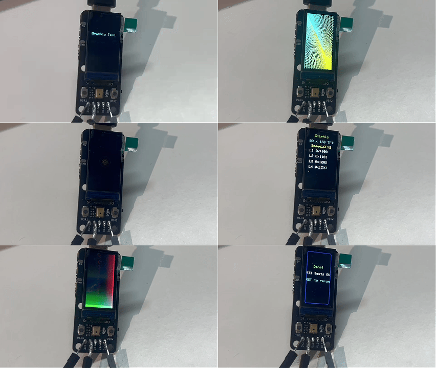
After the sketch runs through all patterns, the screen shows a "Done!" message. Reset the board to run the test again.
IMU
The 0.96'' IPS Display features an onboard 6-axis IMU (LSM6DS3) connected via I2C on D4/D5. The motion interrupt line on D14 supports hardware wake-up and gesture detection.
Both demos below use the LSM6DS3 at I2C address 0x6A.
Demo 1: Electronic Quicksand
This demo turns the screen into an interactive fluid simulation — golden sand particles that flow and settle according to gravity, as measured by the onboard 6-axis IMU. Tilt the board and the sand shifts direction in real time.
Code location: code_GFX2/Function/096_nRF52840/xiao_nrf52840_096_electronic_quicksand/
How It Works
The simulation uses a 13×26 occupancy grid overlaid on the 80×160 screen, where each cell is 6×6 pixels. Around 65 particles are placed in the grid, each with a position, velocity, and a golden color gradient.
The IMU is read via I2C (D4/D5) using the Seeed Arduino LSM6DS3 library at address 0x6A. Raw acceleration values are low-pass filtered and used to derive a gravity vector. When you tilt the board:
- Gravity vector updates — accelerometer data is smoothed with an exponential moving average to avoid jitter.
- Particle velocity — each particle accelerates in the direction of the gravity vector, with damping and a per-particle mobility factor based on its depth in the flow.
- Cell occupancy — particles deeper in the flow (closer to the "bottom" relative to gravity) have reduced mobility, creating a realistic packing effect.
- Differential rendering — only cells where particles moved into or out of are redrawn, minimizing SPI traffic and keeping the animation smooth on the small panel.
Particles near the surface flow freely (higher mobility); particles buried deeper pack tightly (lower mobility) — mimicking how real sand behaves.
Running the Demo
Step 1. Open xiao_nrf52840_096_electronic_quicksand.ino in Arduino IDE.
Step 2. Select the board and port, then click Upload.
Step 3. Once uploaded, the screen fills with golden particles at the bottom. Tilt the board in different directions — the sand flows as if pulled by gravity.
Step 4. Open Tools > Serial Monitor (115200 baud) to confirm initialization:
LCD w=80 h=160
=== Electronic Quicksand 0.96 ===
imu.begin=0
Expected Result
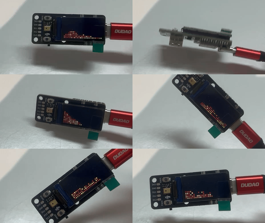
The golden sand particles flow smoothly as you tilt the board. When held flat, the sand settles at the bottom of the screen. Rotate the board 90 degrees and the sand flows to the new "bottom" within a second.
Demo 2: Raise to Wake
This demo implements a screen sleep/wake system driven by the IMU's built-in motion interrupt on D14. The screen automatically turns off (backlight off + nRF52 system ON sleep) after a configurable idle period, and wakes instantly when you pick up or move the device.
Code location: code_GFX2/Function/096_nRF52840/xiao_nrf52840_096_wakeup/
How It Works
The demo uses the LSM6DS3's embedded wake-up event detector — a hardware feature that monitors accelerometer data internally and asserts the INT1 pin (routed to D14 on this board) when motion exceeds a configurable threshold. This means the MCU does not need to poll the accelerometer continuously.
IMU configuration (LSM6DS3):
| Register | Value | Purpose |
|---|---|---|
CTRL3_C | 0x44 | Block data update (BDU) + auto-increment |
CTRL1_XL | 0x40 | Accelerometer @ 104 Hz, ±2g |
TAP_CFG | 0x80 | Enable embedded interrupts |
WAKE_UP_THS | 0x05 | Wake-up threshold (medium-low sensitivity) |
WAKE_UP_DUR | 0x00 | No duration filter (responsive wake) |
MD1_CFG | 0x20 | Route wake-up to INT1 |
Sleep/wake flow:
- Active state — screen is on, backlight at full brightness, UI refreshes every 250 ms with real-time IMU data.
- Auto-sleep — after 8 seconds of inactivity, the sketch turns off the backlight, displays a "Sleep — Move to wake" message, and enters nRF52 System ON sleep (low-power mode with RAM retention). The IMU wake interrupt on D14 was already configured at startup, so motion detection remains active during sleep.
- Wake-up — when the user picks up the board, the IMU detects motion and asserts D14 HIGH. The nRF52840 exits System ON sleep, turns the backlight back on, and redraws the UI — the LCD and IMU keep their state because System ON sleep retains RAM.
Manual test buttons:
| Button | Pin | Action |
|---|---|---|
| USR1 | D6 | Force sleep |
| USR2 | D7 | Force wake |
Running the Demo
Step 1. Open xiao_nrf52840_096_wakeup.ino in Arduino IDE, select the board and port, and click Upload.
Step 2. The screen shows a compact dashboard with power state, motion data, and a countdown. Let the board sit still — it will automatically enter sleep after 8 seconds.
Step 3. Pick up the board or shake it gently — the screen wakes immediately.
Step 4. Open Tools > Serial Monitor (115200 baud) to observe the boot and sleep/wake transitions:
=== XIAO nRF52840 Plus 0.96 IMU Wake Demo ===
[LCD] OK 0.96 ST7789 80x160
[IMU] LSM6DS3 begin=0
[IMU] CTRL1_XL    = 0x40
[IMU] TAP_CFG     = 0x80
[IMU] MD1_CFG     = 0x20
[IMU] WAKE_UP_THS = 0x05
[IMU] D14 wake interrupt OK
[IMU] D14 pin state = 0
[BOOT] done. Screen should be on.
[SLEEP] screen off, entering System ON sleep
[SLEEP] loops=1 D14=0 awake=N
[SLEEP] loops=1025 D14=0 awake=N
[WAKE] D14 pin HIGH (polled)
[WAKE] src=0xA
[WAKE] reason=IMU_D14 wakeCount=8 sleptMs=4142 sleepLoops=1936 wakeSrc=0xA
[WAKE] src=0x0
The sleptMs, sleepLoops, and wakeSrc fields vary depending on how long the board slept and what gesture triggered the wake.
Expected Result
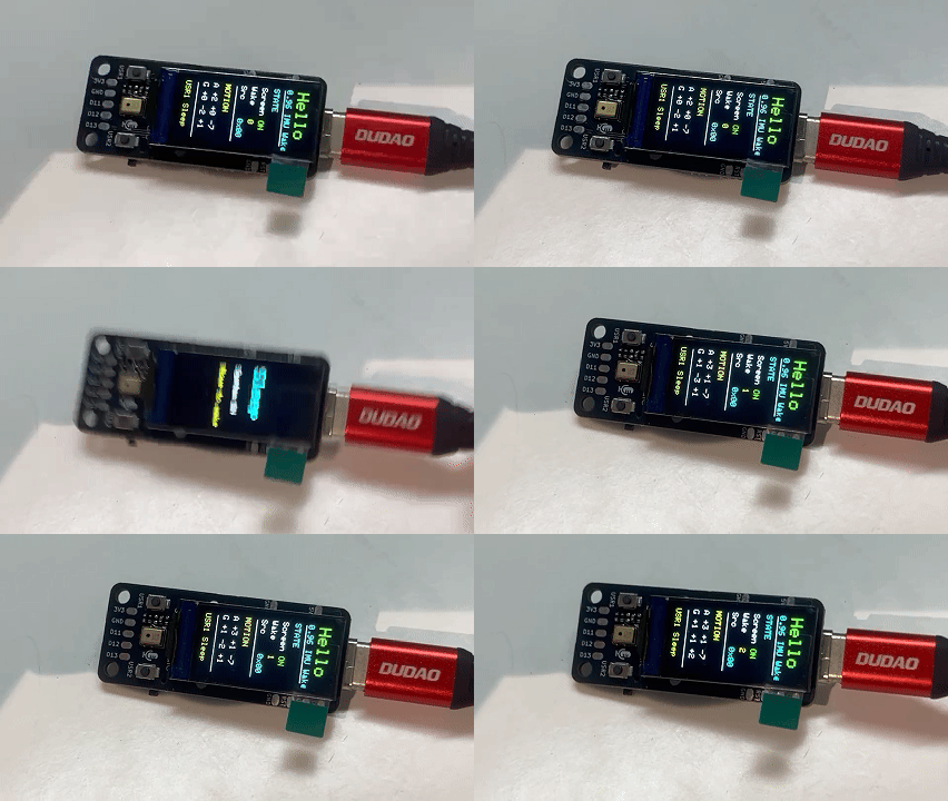
The screen displays real-time motion data while awake. After 8 seconds of stillness, the screen goes dark and the nRF52840 enters low-power sleep. Pick up the device and the screen restores instantly, with the wake counter incremented.
Microphone & Speaker — Flash Recorder
This demo turns the 0.96'' IPS Display into a tiny voice recorder. Press USR1 to capture a short clip from the onboard PDM microphone into the nRF52840's internal flash filesystem, then press USR2 to play it back through an external I2S amplifier.
The 0.96'' IPS Display's PDM microphone connects to the same pins as the other XIAO display boards:
| Pin | Signal | Function |
|---|---|---|
| D0 | PDM_CLK | PDM clock output to microphone |
| D1 | PDM_DATA | PDM data input from microphone |
Code location: code_GFX2/Function/096_nRF52840/xiao_nrf52840_096_flash_record/
Hardware Setup
The playback side needs an external I2S amplifier. The demo is written for the MAX98357A breakout, wired to the 0.96'' IPS Display's I2S test pads:
| XIAO Pin | I2S Signal | MAX98357A |
|---|---|---|
| 3V3 | Power | VIN |
| GND | Ground | GND |
| D11 | I2S_SD (data out) | DIN |
| D12 | I2S_SCK (bit clock) | BCLK |
| D13 | I2S_WS (word select) | LRC |
Disconnect the USB power before wiring the amplifier and speaker. Connect the speaker to the SPK+ and SPK- terminals of the MAX98357A — do not connect either speaker wire to GND.
The 0.96'' IPS Display does not have an SD card slot, so this demo records into the nRF52840's internal flash filesystem (InternalFS). InternalFS is about 28 KB — the tutorial records 11,200 mono samples at 16 kHz, producing about 22 KB of PCM audio and a recording duration of approximately 0.7 seconds.
How It Works
Display:
The screen is driven by Seeed_GFX2 with Board_XIAO_0inch96_LCD<38, 37> and Config_Seeed_0inch96_LCD_ST7789 (80×160, BGR, rotation 2) over 10 MHz hardware SPI.
Recording (USR1):
- The sketch starts the PDM peripheral at 16 kHz, single channel and captures raw samples into a 11200-sample buffer (≈ 0.7 s, ≈ 22 KB of PCM) through an ISR (
onPdmData). - A progress screen shows the recording percentage and elapsed time in real time.
- When the buffer is full, the sketch prepends a 44-byte WAV header and writes the file
/REC_RAW.WAVto InternalFS.
Playback (USR2):
- The WAV is loaded back from InternalFS.
- The sketch drives the nRF52840's I2S peripheral in master mode with a 32× ratio (≈ 16 kHz LRCK), sending 16-bit stereo frames to the MAX98357A at 0.75× gain (each mono sample is duplicated to both channels).
- A double-buffer (ping-pong) scheme keeps the audio stream uninterrupted until the clip ends.
Buttons:
| Button | Pin | Action |
|---|---|---|
| USR1 | D6 | Record a new clip (overwrites the previous one) |
| USR2 | D7 | Play back the saved clip |
The PDM, Adafruit TinyUSB, Adafruit LittleFS, and InternalFileSystem libraries are bundled with Seeed nRF52 Boards 1.1.13 — do not install separate versions from the Library Manager. This tutorial does not use SdFat.
Running the Demo
Step 1. Open xiao_nrf52840_096_flash_record.ino in Arduino IDE.
Step 2. Select Tools > Board > Seeed nRF52 Boards > Seeed XIAO nRF52840 Plus and the correct Port.
Step 3. Click Upload.
Step 4. The screen shows the "Recorder" idle screen. Press USR1 — a red "REC" progress bar fills as it records. When done, it saves the WAV and returns to the idle screen.
Step 5. Press USR2 — the clip plays through the connected MAX98357A speaker, with the screen showing "Playing...".
Expected Result
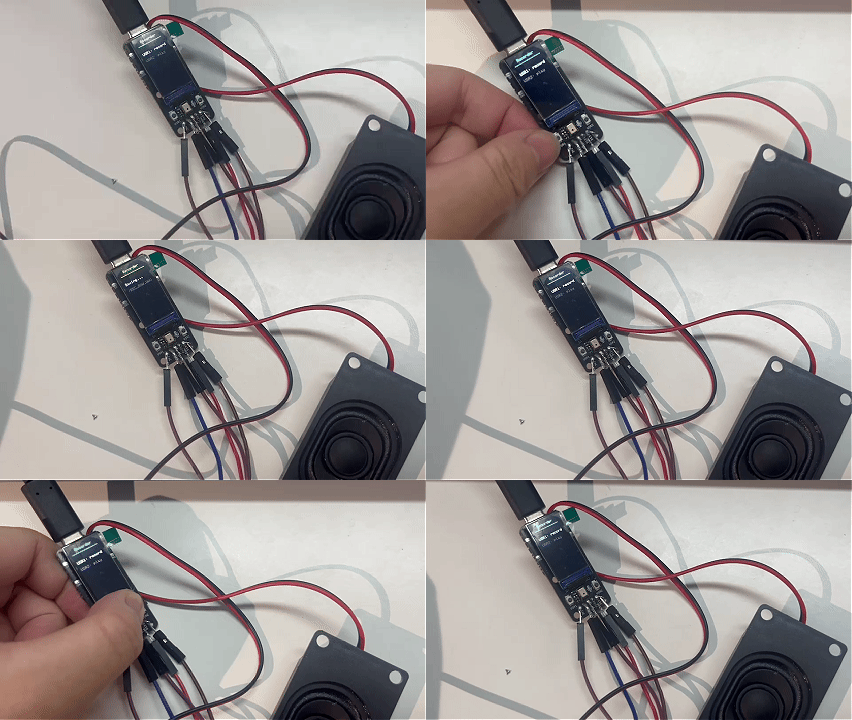
After pressing USR1, the red progress bar fills to 100% and the clip is saved. Pressing USR2 plays the recording back through the MAX98357A. The WAV file is stored in InternalFS and remains available after a reset or power cycle. Recording again with USR1 overwrites the previous file.
This tutorial has been compiled, uploaded, and hardware-tested with the XIAO nRF52840 Plus, the 0.96'' IPS Display, a MAX98357A amplifier, and an external speaker.
User Buttons
The 0.96'' IPS Display has two physical push buttons connected to the XIAO nRF52840 Plus:
| Button | Pin | Logic | Silkscreen Label |
|---|---|---|---|
| USR1 | D6 | Active-low (pressed = LOW) | USR1 |
| USR2 | D7 | Active-low (pressed = LOW) | USR2 |
Unlike the 1.14'' IPS Display, the 0.96'' IPS Display has no third button (no USR3 on D19). It also has no dedicated button breakout pads.
Reading Buttons
The onboard demos configure the buttons with the internal pull-up:
const int USR1 = D6;
const int USR2 = D7;

void setup() {
  pinMode(USR1, INPUT_PULLUP);
  pinMode(USR2, INPUT_PULLUP);
  Serial.begin(115200);
}

void loop() {
  if (digitalRead(USR1) == LOW) {
    Serial.println("USR1 (D6) pressed");
    delay(200); // simple debounce
  }
  if (digitalRead(USR2) == LOW) {
    Serial.println("USR2 (D7) pressed");
    delay(200);
  }
}
Debounce with Interrupts
For responsive, debounced button handling without blocking the main loop, you can use pin-change interrupts:
volatile bool btn1Flag = false;
volatile bool btn2Flag = false;

void btn1Isr() { btn1Flag = true; }
void btn2Isr() { btn2Flag = true; }

void setup() {
  pinMode(D6, INPUT_PULLUP);
  pinMode(D7, INPUT_PULLUP);
  attachInterrupt(digitalPinToInterrupt(D6), btn1Isr, FALLING);
  attachInterrupt(digitalPinToInterrupt(D7), btn2Isr, FALLING);
}

void loop() {
  if (btn1Flag) {
    btn1Flag = false;
    delay(30); // debounce settling time
    if (digitalRead(D6) == LOW) {
      // handle USR1 press
    }
  }
  if (btn2Flag) {
    btn2Flag = false;
    delay(30);
    if (digitalRead(D7) == LOW) {
      // handle USR2 press
    }
  }
}
Default Behavior in the Factory Dashboard
In the preloaded factory firmware, the buttons are mapped as follows (you can override these in your own code):
| Button | Pin | Action |
|---|---|---|
| USR1 | D6 | Cycle screen brightness (100% → 75% → 50% → 25% → 100%) |
| USR2 | D7 | Toggle screen backlight ON/OFF |
When the screen is off (toggled via USR2), pressing USR2 again restores it to the previous non-zero level.
Battery Status
This demo shows the battery status — a battery icon with charge level and charging state — on the 0.96'' IPS Display. It detects whether a LiPo battery is physically connected and shows one of three states: USB PWR (no battery), percentage (battery only), or charging (USB + battery).
The 0.96'' IPS Display has no dedicated battery ADC pin (D16 is NC) — battery voltage is measured through the XIAO nRF52840 Plus module's internal divider.
Code location: code_GFX2/Function/096_nRF52840/xiao_nrf52840_096_battery_status/
How It Works
Display:
The screen is driven by Seeed_GFX2 with Board_XIAO_0inch96_LCD<38, 37> and Config_Seeed_0inch96_LCD_ST7789 (80×160, BGR, rotation 2) over 10 MHz hardware SPI.
Battery circuit:
The nRF52840 Plus uses three GPIO pins to form a complete battery monitoring system:
| Signal | nRF52840 Pin | Function |
|---|---|---|
READ_BAT | P0.14 | Battery voltage divider enable. Active-low — set LOW to enable the divider, then release to HIGH (high-impedance) to save power. |
VBAT_ADC | PIN_VBAT (AIN7 / P0.31) | Analog input reading the divided battery voltage. |
CHG | P0.17 | Charging status indicator. Active-low — reads LOW when a charger is connected and the battery is charging. |
Detection:
Under USB-C, a static VBAT voltage cannot tell whether a battery is present — the charger's BAT node can look like a real Li-ion cell even with no battery attached. So the demo first learns a USB-only baseline, then confirms battery insertion only after a sustained downward VBAT shift, and confirms removal after a noisy/jumped reading combined with ~CHG going HIGH. This mirrors the factory Dashboard's detection logic.
Icon states:
- No battery — grey outline battery with a red cross, labelled USB PWR.
- Battery present — white outline battery with a coloured fill (green / yellow / red by percentage), labelled with the percentage and voltage.
- Charging — cyan fill with a lightning-bolt icon, labelled with the percentage and voltage.
The ~CHG pin is read through the nRF52840's raw GPIO registers (nrf_gpio_cfg_input() and NRF_P0->IN) instead of digitalRead(). In the Arduino API, pin numbers follow the board package's mapping, where digitalRead(17) actually reads P0.07 (the 6D IMU's I2C data line) rather than P0.17. The constants 14 and 17 here are raw Nordic P0.x pin numbers (P0.14 and P0.17), which is exactly what the register calls expect.
The demo uses the factory-calibrated 499 kΩ low-side resistor (divider ratio ≈ 3.004), not the 510 kΩ nominal value. The divider is built into the XIAO nRF52840 Plus module itself, not the display board. The P0.14 enable pin is active-low: drive it LOW to enable the divider, then release it to high-impedance (INPUT) to minimize quiescent current drain when the battery is not being measured.
Running the Demo
Step 1. Open xiao_nrf52840_096_battery_status.ino in Arduino IDE.
Step 2. Select Tools > Board > Seeed nRF52 Boards > Seeed XIAO nRF52840 Plus and the correct Port.
Step 3. Click Upload.
Step 4. Observe the screen — it shows the battery icon with the current state. Plug or unplug a LiPo battery (or the USB-C cable) to watch the icon switch between the three states.
Expected Result
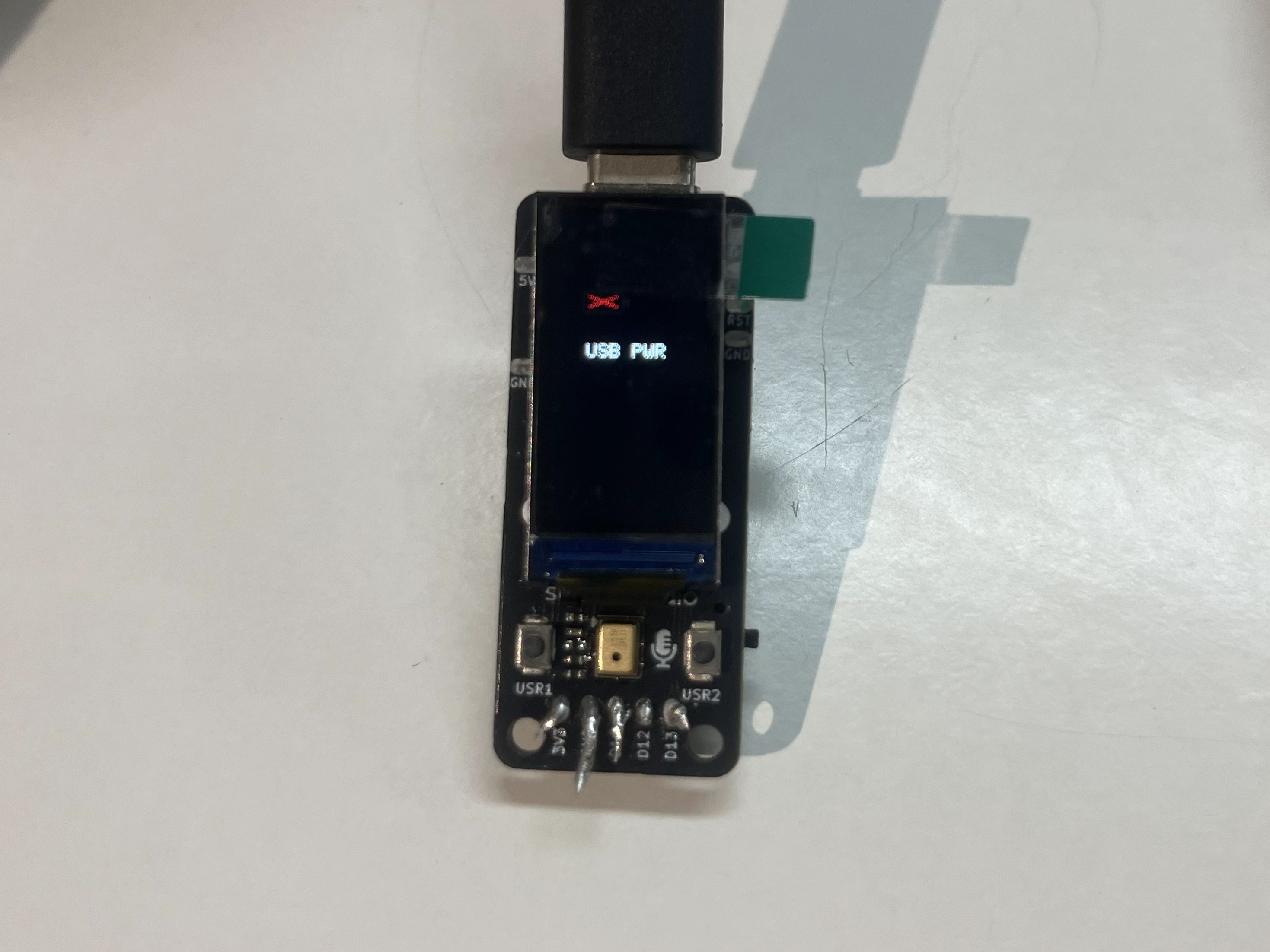 USB PWR (no battery) | 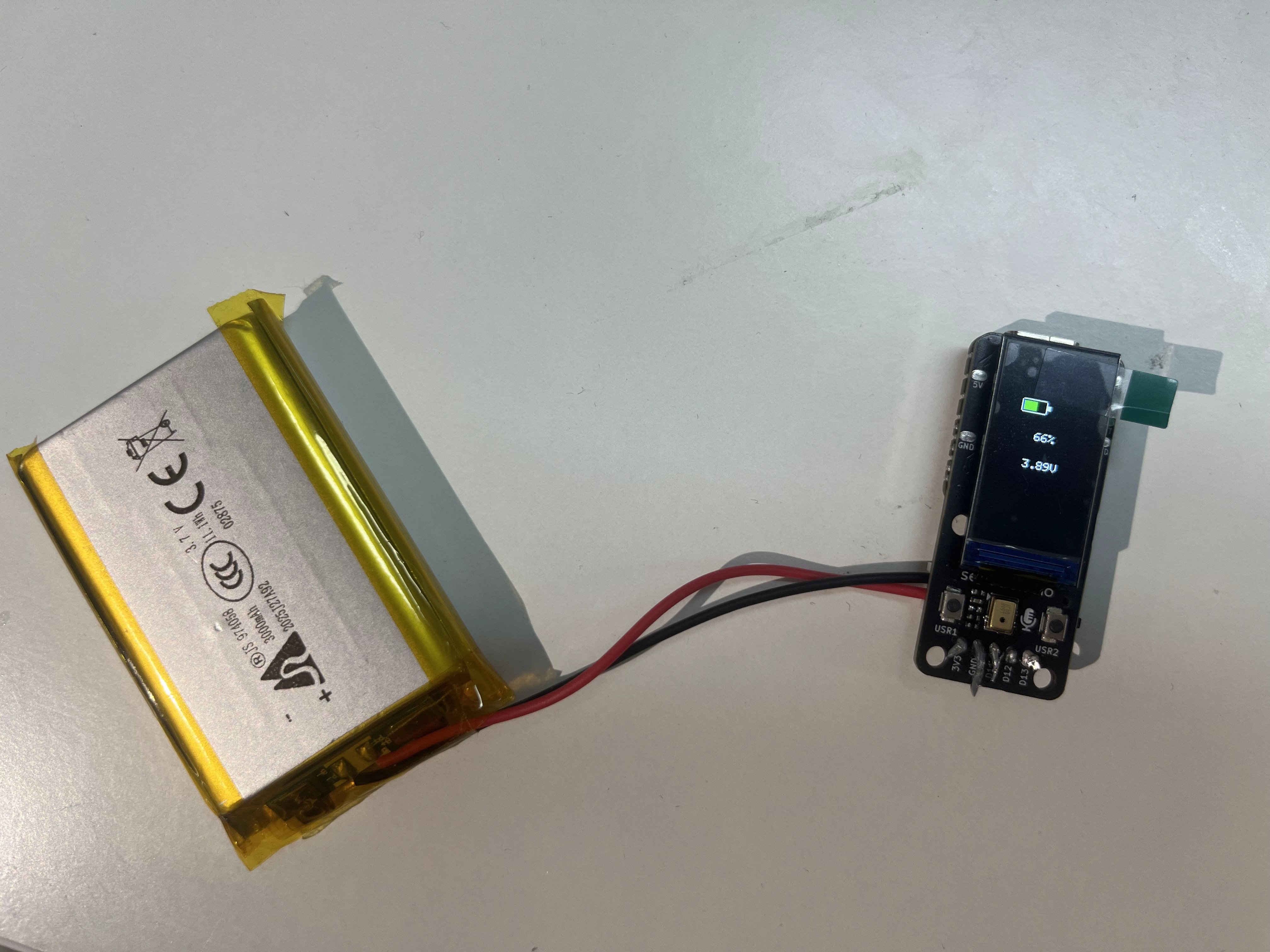 Percentage (battery only) |
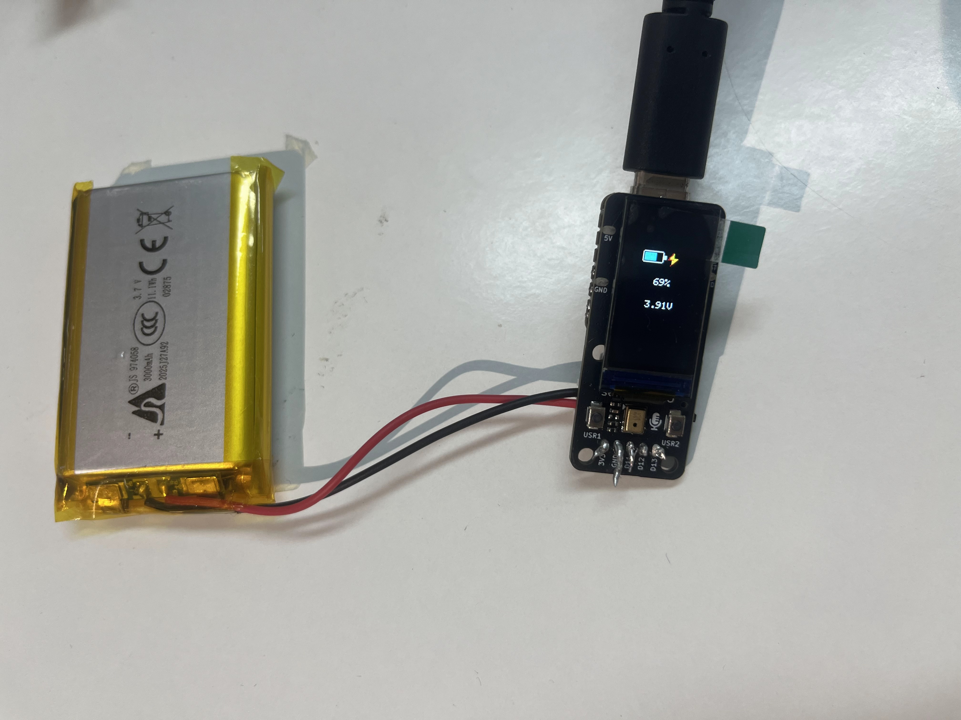 Charging (USB + battery) | 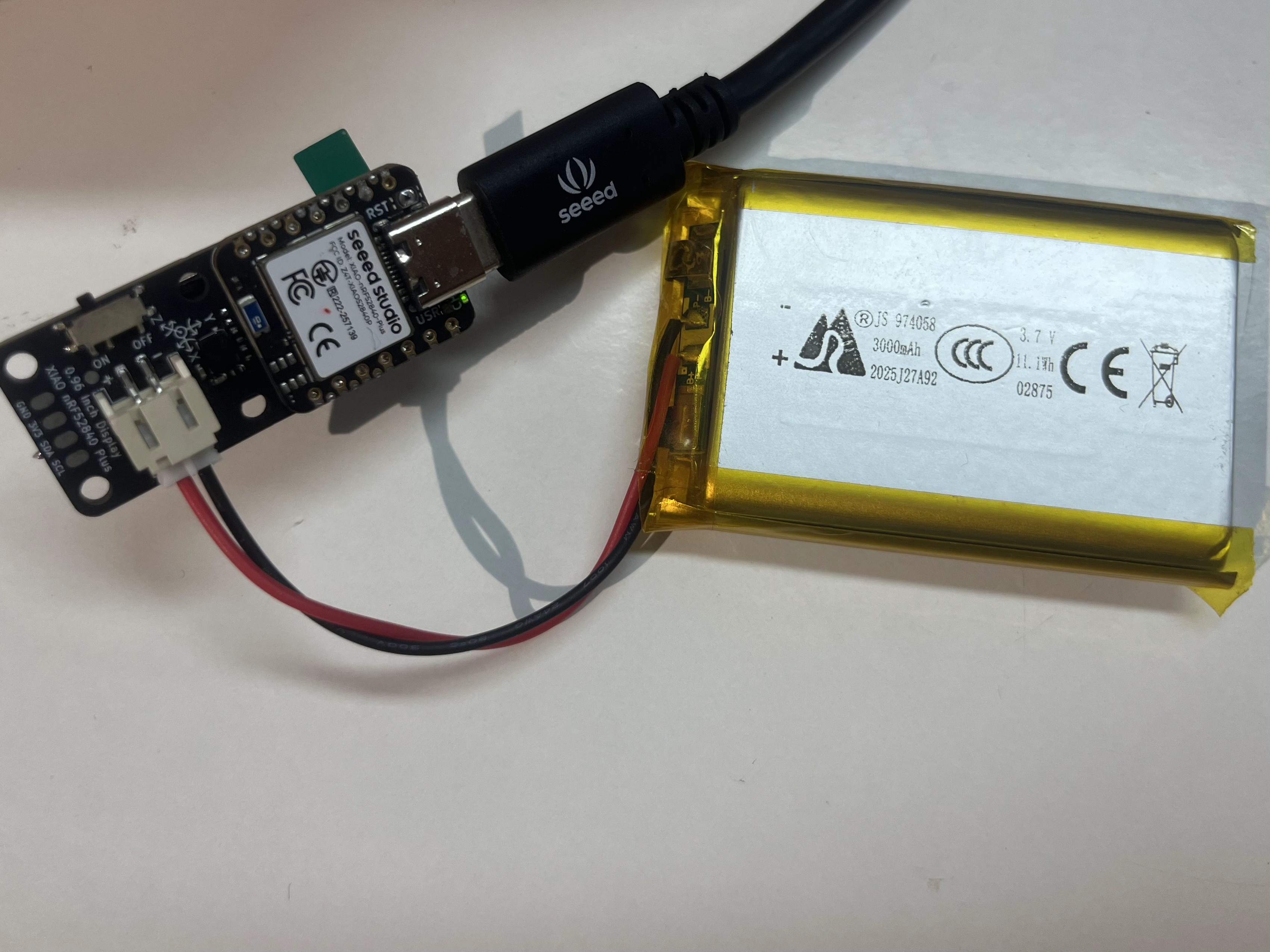 Battery connector (back) |
Without a battery, the screen shows a grey battery with a red cross and the label USB PWR. Insert a LiPo battery and the icon switches to a coloured fill with the percentage and voltage. Plug in USB-C while a battery is present and the fill turns cyan with a lightning bolt, indicating charging.
The demo also prints a diagnostic line to the Serial Monitor every 500 ms, for example:
VBAT 3.87V charging 85 spread=5 usb=ON base=4.140 baseValid=Y state=PRESENT filter=STABLE removeCount=0
Resources
- 🗃️[PCB Design Files] XIAO 0.96'' IPS Display (nRF52840) KiCad Project
- 📄[Schematic] XIAO 0.96'' IPS Display (nRF52840) Schematic
- 📦[3D Model] XIAO 0.96'' IPS Display (STEP)
- 🖨️[3D Printed Enclosure] XIAO 0.96'' IPS Display Enclosure (by gokul)
- 📄[Datasheet] 0.96 Inch Display Datasheet
- 💾[Factory Firmware] XIAO 0.96'' IPS Display (nRF52840) Factory Firmware
- [Demo] XIAO Display Board Demo Code — all Function demos are in the
code_GFX2/Function/096_nRF52840/directory
Tech Support & Product Discussion
Thank you for choosing our products! We are here to provide you with different support to ensure that your experience with our products is as smooth as possible. We offer several communication channels to cater to different preferences and needs.