Get Started with Meshtastic
When the device is in either of the states below, do not manually reboot or turn it off. Otherwise, the device may become bricked.
- Not finishing the message transmission process
- Being configured
Get Started
Before formal deployment, please test and configure the node first.
Flash Firmware
Do not use NRF-OTA to update the firmware, as it may cause the device to become completely unresponsive.
Before flashing the firmware, please run the flash erase step first!
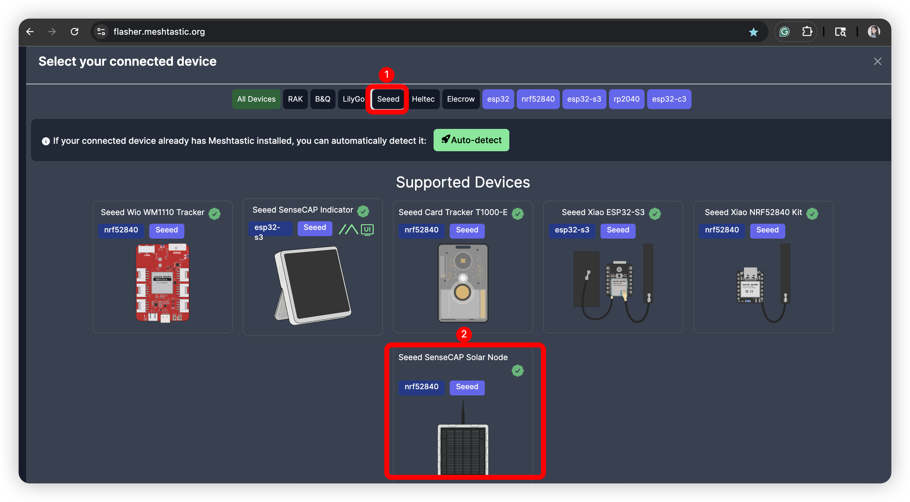
Visit Meshtastic Web Flasher. Select Seeed SenseCAP Solar Node as the target device.
Flash Erase
Click the trash symbol.
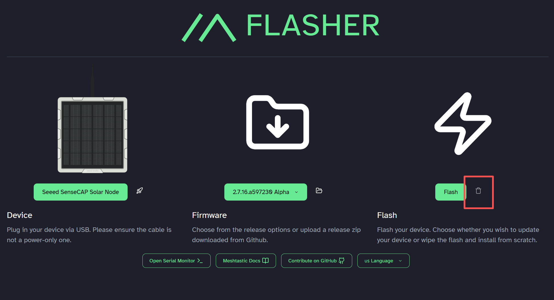
Download and copy the erase firmware.
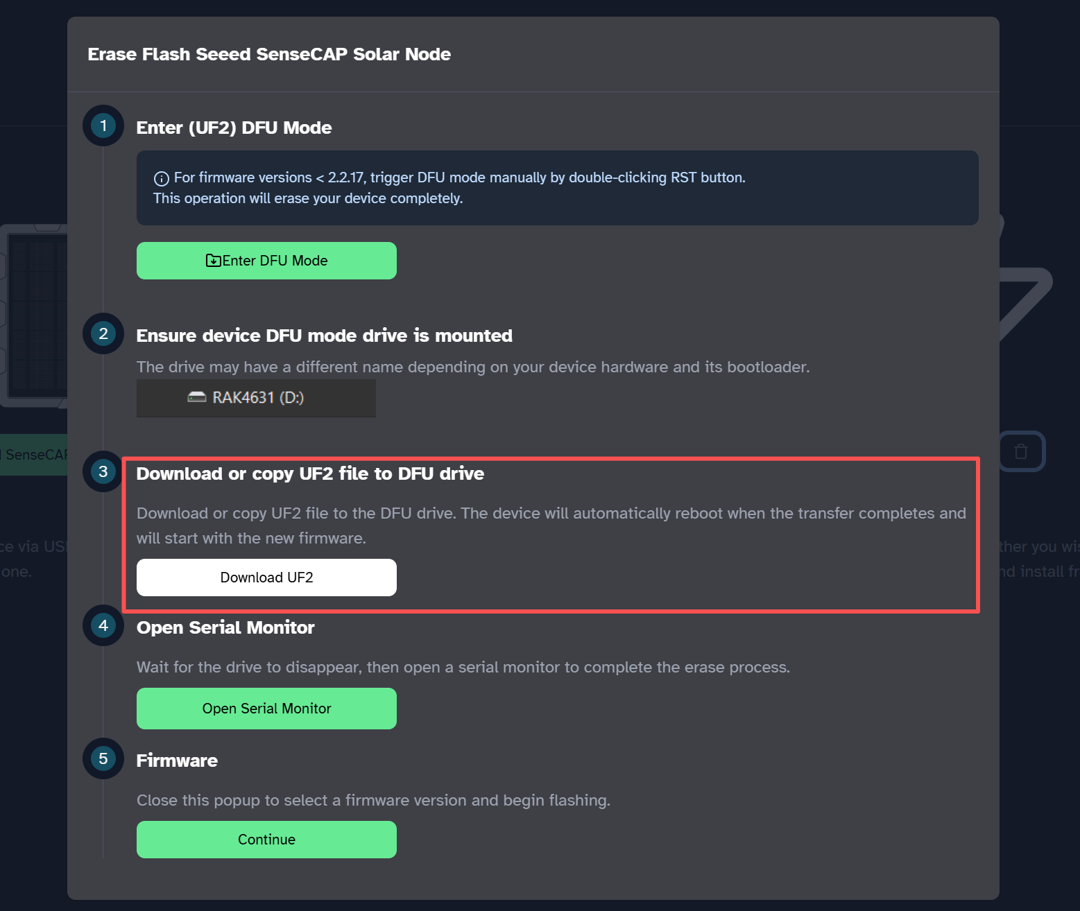
Click Enter DFU Mode, select and connect to the serial port named XIAO-xxx, and a drive named XIAO-xxx should appear. Copy the erase firmware to the drive.

This process may take some time. Please wait for the "XIAO-XXX" drive to disappear.
Flash Application Firmware
Choose the firmware version you want. Click flash.
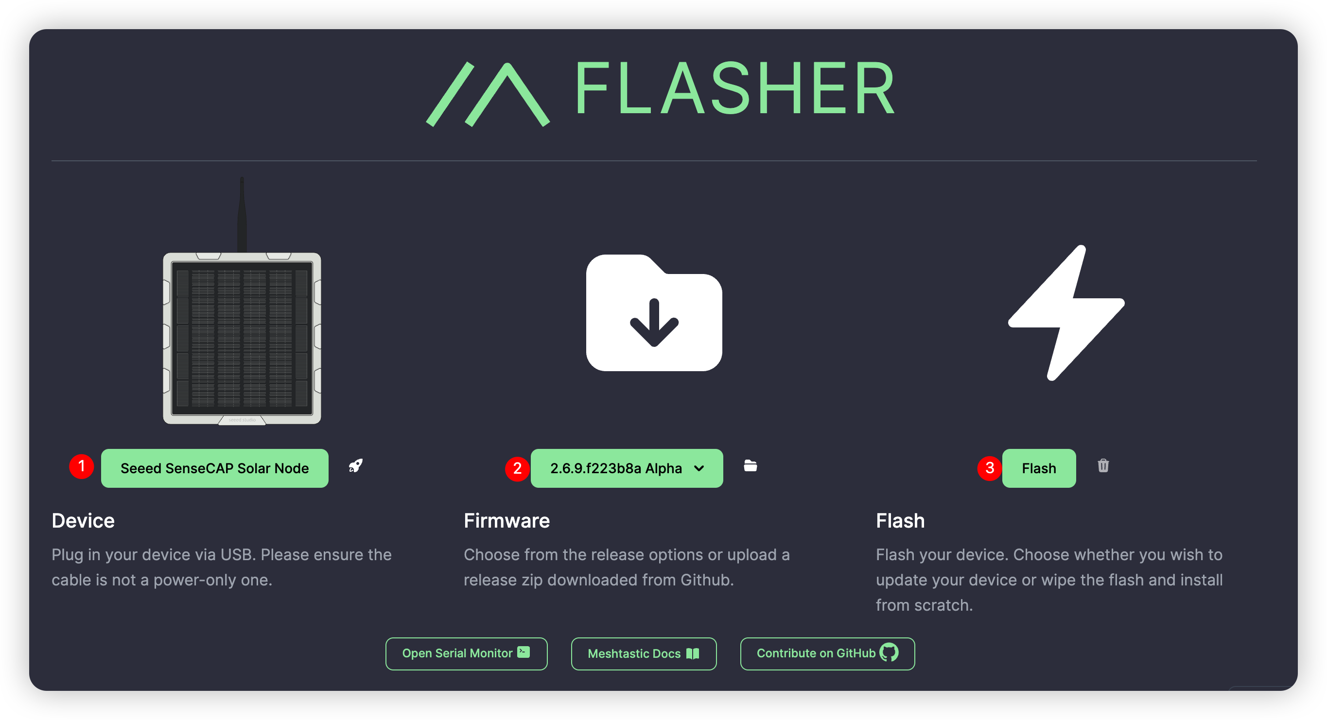
Download the UF2 file and enter DFU mode. Drag the UF2 file to the DFU drive. The firmware should be flashed after the file is copied and the device reboots.
Install Battery and GPS Module (Optional)
When you need to install or replace the battery, use a button-top 18650 (3.6 V) battery.

The P1-Pro version has a built-in battery and GPS module. For the P1 version, users need to install the battery and GPS module manually if needed.
- Step 1: Remove all the screws and the cover.

- Step 2: Install the battery and GPS module.


- Step 3: Assemble the shell.
Ensure that the shell is properly mounted and the screws are firmly tightened to maintain the device’s waterproof integrity.
Power on the device
The device needs to be activated by connecting the USB cable before first use. If the blue Mesh light blinks, the device has been successfully turned on, as shown in the video below:
If the device does not respond when you press the button, please charge it first. Do not use a fast charger.
Connect via App
- iOS App
- Android App
- Select the target device on the Bluetooth panel.
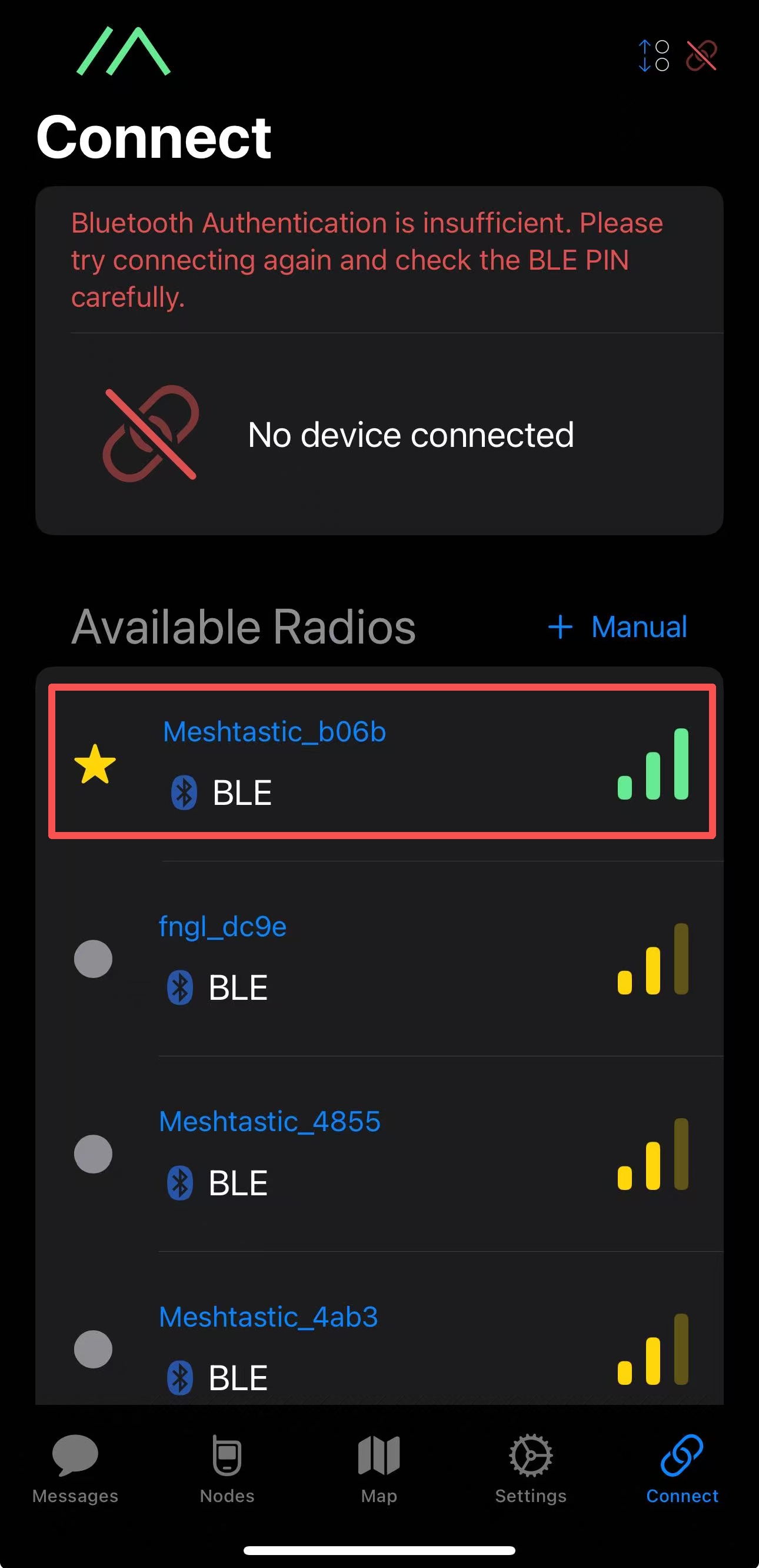
- Enter the code (the default code is
123456) and then clickOKto connect the device.
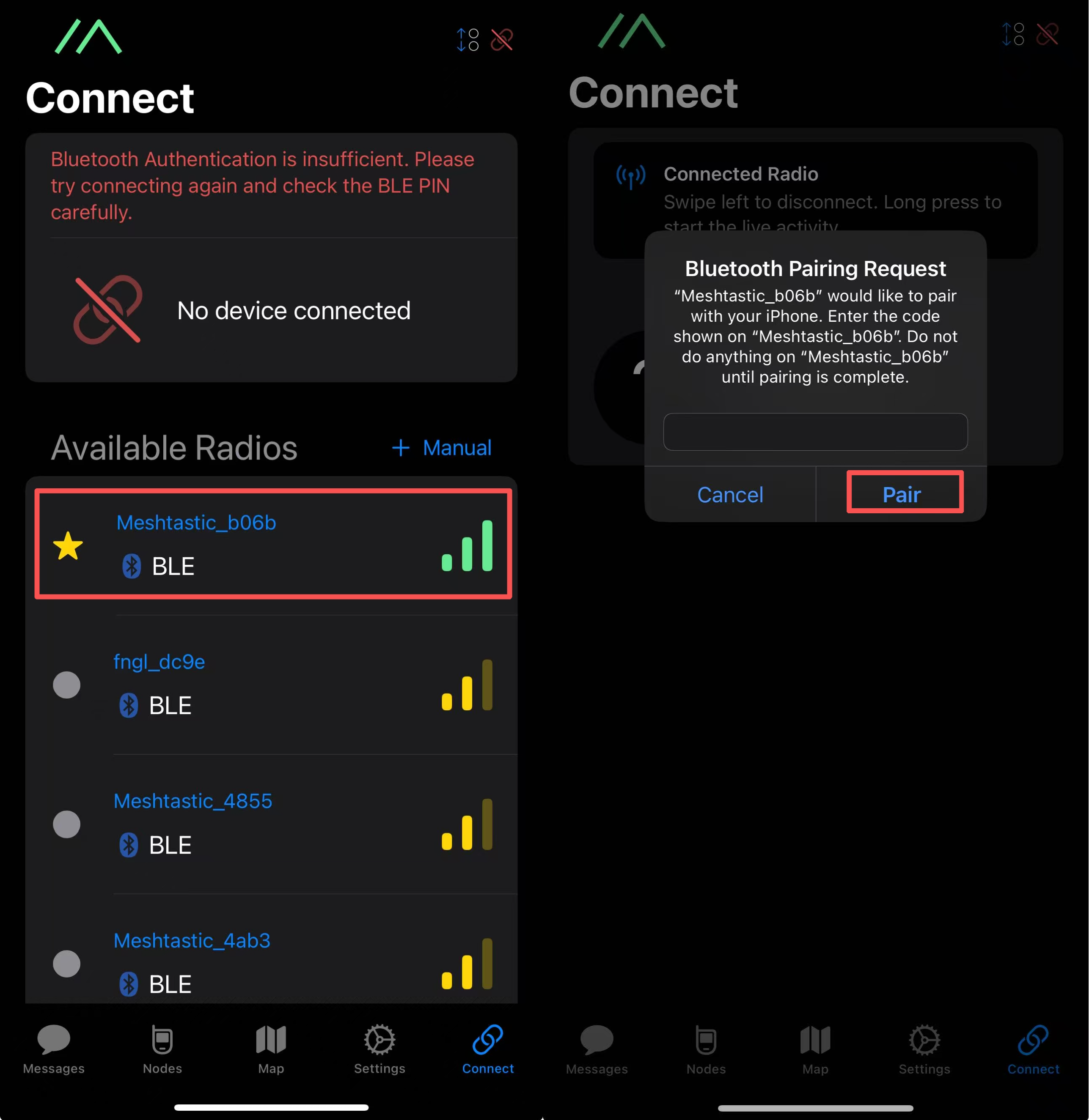
- Click
+and choose the target device.

- Enter the code (the default code is
123456) and then clickOKto connect the device.

Connect via Website
If you want to send text messages and communicate with other nodes in the web client, you can connect the device to the Meshtastic Web Client now.
Step 1: Open the Website
Click here to go to the website.

Step 2: Add the new device
Click "+ New Connection".

There are two ways to connect. You can choose your preferred method.
Method 1: Via Bluetooth
Choose the Bluetooth method. Select the device ID in the pop-up window.

Method 2: Via Serial
Choose the serial method. Open the device manager to see which port the device is connected to. Select that port in the pop-up window.

Your device will be shown in the list. Click to connect. If the connection succeeds, you can see the device status directly on the website.

Configure the LoRa
In order to start communicating over the mesh, you must set your region. This setting controls which frequency range your device uses and should be set according to your regional location.
- iOS App
- Android App
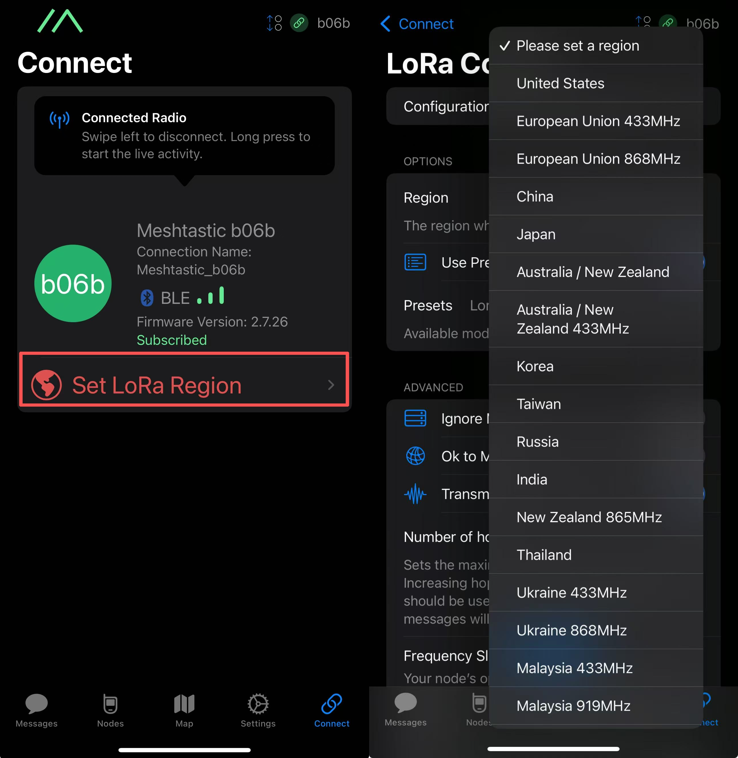

Region List
| Region Code | Description | Frequency Range (MHz) | Duty Cycle (%) | Power Limit (dBm) |
|---|---|---|---|---|
| UNSET | Unset | N/A | N/A | N/A |
| US | United States | 902.0 - 928.0 | 100 | 30 |
| EU_868 | European Union 868MHz | 869.4 - 869.65 | 10 | 27 |
Refer to LoRa Region by Country for a more comprehensive list.
EU_868 has to adhere to an hourly duty cycle limitation of 10%, calculated every minute on a rolling 1-hour basis. Your device will stop transmitting if you reach it, until it is allowed again.
Now that you have set the LoRa region on your device, you can continue with configuring any LoRa Configs to suit your needs.
Configure GPS
Please enable GPS. You can adjust the update interval and broadcast interval to obtain more up-to-date location information.

For iOS, please turn on Accurate Location. Otherwise, the positioning may be inaccurate.

Button
| Button Action | Description |
|---|---|
| Press PWR for 3s | Power on |
| Press PWR twice | Update node/location info |
| Press PWR three times | Switch on/off the GPS |
| Press PWR for 5s | Power off |
| Press RST twice | Manually enter DFU |
Installation
Since the device will be used outdoors for extended periods, please avoid installing the panel in a horizontal position. A tilted or diagonal installation is recommended to prevent water accumulation. Additionally, ensure that all screws are securely tightened and the cover is properly installed. For enhanced waterproof protection, you may also consider applying extra sealing measures.
- Part List

Step-by-step Installation Guidance
- Step 1: Connect part 1 to the bottom of the device using washers and screws.
- Step 2: Connect the universal joint (part 2) and the bracket (part 3) with screws.
- Step 3: Connect the RF cable (part 4) and antenna (part 5).
- Step 4: Install the hoop ring in the appropriate position.
- Step 5: Connect the universal joint bracket.
- Step 6: Loosen the screws, adjust the universal joint to the appropriate position, and then tighten the screws.
- Step 7: Connect the antenna to the device.
Complete installation guidance
- You can complete the entire installation and initialization process through a video.
Add sensors to Solar Node (Optional)
- You can install your sensor by following this video.
- The following sensors have been verified to be compatible with the Grove interface on the device.
| Sensor type | Sensor Model | |
|---|---|---|
| Environmental Sensor | Pressure | BMP085 |
| Temperature | MCP9808、PCT2075 | |
| Temperature & Humidity | SHT31/SHTC3/SHT4X、AHT10 | |
| Temperature & Humidity & Pressure | BME280 | |
| Other | Heart Rate & SpO₂ | MAX30102 |
| I2C Keyboard | CardKB | |
Upgrade Antenna (Optional)
- You can replace the antenna with a fiberglass one by watching this video.
If you need an antenna with higher gain, we recommend the 860-930MHz 3dBi fiberglass antenna and the 902-928MHz 5.8dBi fiberglass antenna.
FAQ
Boot Loop
- Reason
This is usually caused by a firmware flashing failure. When flashing the firmware, please maintain a stable connection.
- Troubleshoot
Click here to re-flash the firmware.
Device bricked
Description
The device does not respond, the LED does not light up, and it cannot pair with your app.
1) Device can still enter the DFU mode, then try to flash the bootloader.
Flash the Bootloader
When you are flashing the bootloader, please make sure the cable connection is stable and DO NOT disconnect it during the flash process.
Step1: Adafruit-nrfutil Installation
For Windows users, press the "Win" key and "R" key, then enter "cmd" in the pop-up window and press "Enter". This opens the command line.
For Mac users, press the "Command" key and "Space" key to open Spotlight. Then enter "terminal" and press "Return". This opens the command line.
For Linux users, open a terminal and use the Linux tab below to install the tool with pipx.
Prerequisites
Check in your command line whether Python and pip are installed successfully. On Linux, use python3 instead of python for these checks.
python --version
python -m pip --version
Then "Python xxx" and "pip xxx" should appear. If they do not, please try installing Python again.
- Installing from PyPI
- Installing from Source
- Linux
For Windows and macOS, install the latest version with the following command. Linux users should use the Linux tab.
pip3 install --user adafruit-nrfutil
Check the installation path:
python -m pip show adafruit-nrfutil
This is the installation location:
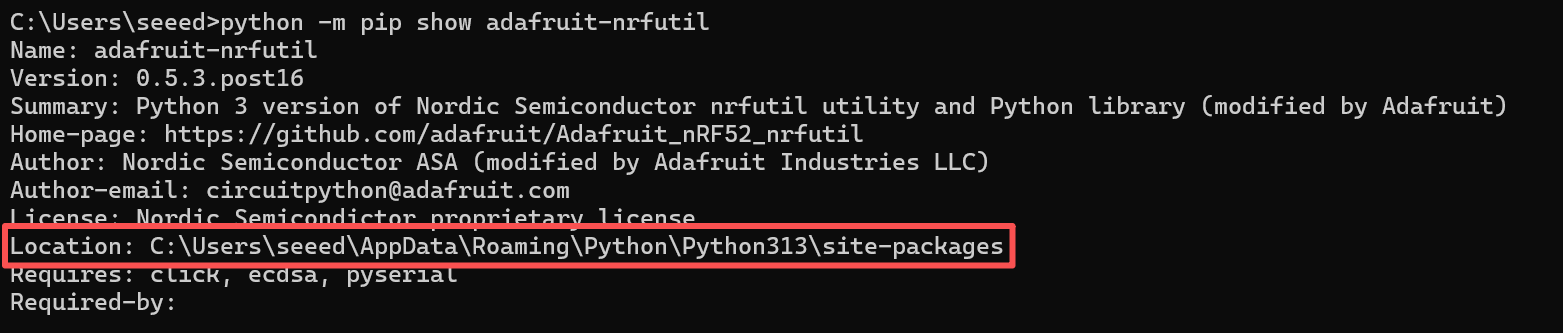
For Windows users, you may need to add the path manually. Copy the installation location shown in the last step. Then add it as follows:

Use this method if you have issues installing with PyPI or want to modify the tool. First, clone this repo and go into its folder.
git clone https://github.com/adafruit/Adafruit_nRF52_nrfutil.git
cd Adafruit_nRF52_nrfutil
Note: The following commands use python3; however, if you are on Windows, you may need to change it to python, since Windows installations of Python 3.x still use the name python.exe.
To install in user space in your home directory:
pip3 install -r requirements.txt
python3 setup.py install
If you get permission errors when running pip3 install, your pip3 is older or is set to try to install in the system directories. In that case use the --user flag:
pip3 install -r --user requirements.txt
python3 setup.py install
If you want to install in system directories (generally not recommended):
sudo pip3 install -r requirements.txt
sudo python3 setup.py install
To generate a self-contained executable binary of the utility (Windows and MacOS), run these commands:
pip3 install pyinstaller
cd Adafruit_nRF52_nrfutil
pip3 install -r requirements.txt
cd Adafruit_nRF52_nrfutil\nordicsemi
pyinstaller __main__.py --onefile --clean --name adafruit-nrfutil
You will find the executable in Adafruit_nRF52_nrfutil\nordicsemi\dist\adafruit-nrfutil (with .exe if you are on Windows).
Copy or move it elsewhere for your convenience, such as a directory in your %PATH%.
On Ubuntu/Debian, install adafruit-nrfutil with pipx. It isolates the tool from the system Python environment and avoids the externally-managed-environment error:
sudo apt update
sudo apt install pipx
pipx install adafruit-nrfutil
pipx ensurepath
On Fedora, use sudo dnf install pipx instead of apt. Reopen your terminal, then verify:
adafruit-nrfutil version
Use adafruit-nrfutil version, not adafruit-nrfutil --version. If the command is not found, check that pipx ensurepath completed and reopen your terminal.
Step2: Check your port number
Connect your device to your PC, and check the port number.
For Windows users, for example:
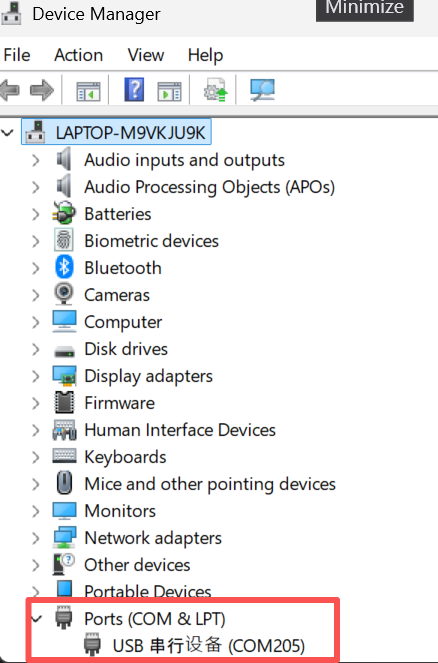
For Mac users, for example:

For Linux users:
Connect the Solar Node P1 / P1-Pro with a USB data cable. Compare the following output before and after connecting it to identify its serial port:
ls /dev/ttyACM*
The device usually appears as /dev/ttyACM0; if nothing is listed, also try ls /dev/ttyUSB*. To enter DFU mode manually, double-press the device's RST button, then check the port again. Use the current DFU port for flashing.
Check the port permissions, replacing /dev/ttyACM0 with your actual port:
ls -l /dev/ttyACM0
On Ubuntu/Debian, serial ports usually belong to the dialout group. If you get Permission denied and the port belongs to dialout, add your user to that group:
sudo usermod -aG dialout "$USER"
Log out and log back in for the change to take effect. On other distributions, use the serial-access group shown by ls -l and follow your distribution's instructions.
Step3: Flash the bootloader
In the terminal or command prompt, navigate to the directory where you downloaded the bootloader zip package and execute the following command, replacing the port with the correct one for your device:
Keep xiao_nrf52840_ble_bootloader.zip as a ZIP file; do not extract it. Close any serial monitor or browser flasher connected to the device. If the device is already in DFU mode after double-pressing RST, omit --touch 1200 and use its current DFU port.
- For Windows:
adafruit-nrfutil --verbose dfu serial --package xiao_nrf52840_ble_bootloader.zip -p COMXX -b 115200 --singlebank --touch 1200
Please change COMXX to your COM port number. For example, if your device is on COM6, change the command to:
adafruit-nrfutil --verbose dfu serial --package xiao_nrf52840_ble_bootloader.zip -p COM6 -b 115200 --singlebank --touch 1200
If the serial port changes after this command, follow Step 4 below.
- For macOS:
adafruit-nrfutil --verbose dfu serial --package xiao_nrf52840_ble_bootloader.zip -p /dev/tty.SLAB_USBtoUART -b 115200 --singlebank --touch 1200
- For Linux:
If you entered DFU mode manually in Step 2, run this command without --touch 1200. Replace /dev/ttyACM0 with your current DFU port:
adafruit-nrfutil --verbose dfu serial --package xiao_nrf52840_ble_bootloader.zip -p /dev/ttyACM0 -b 115200 --singlebank
If the device is still running application firmware and has a serial port, you can append --touch 1200 to request DFU mode. If it does not respond, double-press RST, identify the DFU port again, and use the command without --touch 1200.
Step4: Handle a serial port change
--touch 1200 requests DFU mode by opening and closing the serial port at 1200 baud. The operating system may then assign a different port. If the output shows Touched serial port followed by a port-not-found error, check whether a new DFU port has appeared. This error alone does not confirm a successful flash or mean the device is damaged.
Keep the USB cable connected. On Linux, run ls /dev/ttyACM* again (or ls /dev/ttyUSB* if applicable). On Windows, refresh Device Manager; on macOS, check ls /dev/cu.*. Retry using the new DFU port and omit --touch 1200. For example, if the new Linux port is /dev/ttyACM1:
adafruit-nrfutil --verbose dfu serial --package xiao_nrf52840_ble_bootloader.zip -p /dev/ttyACM1 -b 115200 --singlebank
Use your actual port name. If the port cannot be opened, check its permissions as described in Step 2 and make sure no other application is using it. If no DFU port appears, double-press RST and check again before retrying.
Step5: Confirm the result and reinstall the application firmware
Wait for the transfer to finish and the tool to print:
Device programmed.
This message confirms that the bootloader transfer completed successfully. Keep the cable connected during the transfer. A port change or the appearance of a USB drive alone is not confirmation of a successful flash.
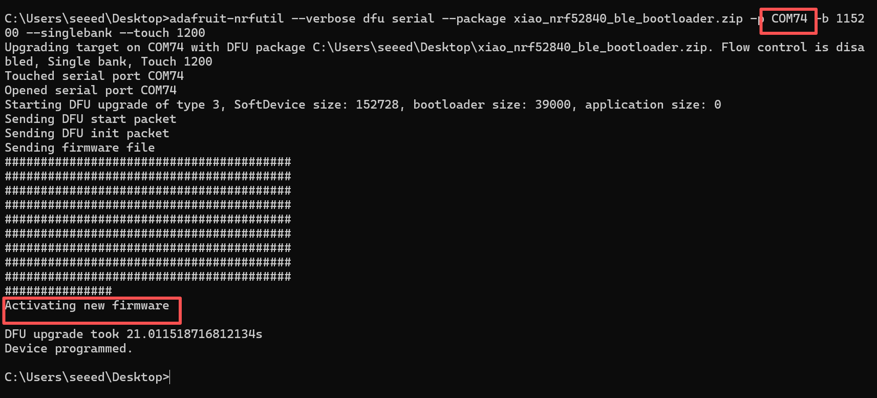
Flashing the bootloader does not reinstall the Meshtastic application firmware. After the successful transfer, follow Flash Firmware to install it before using the device.
Unable to Communicate on the Primary Channel
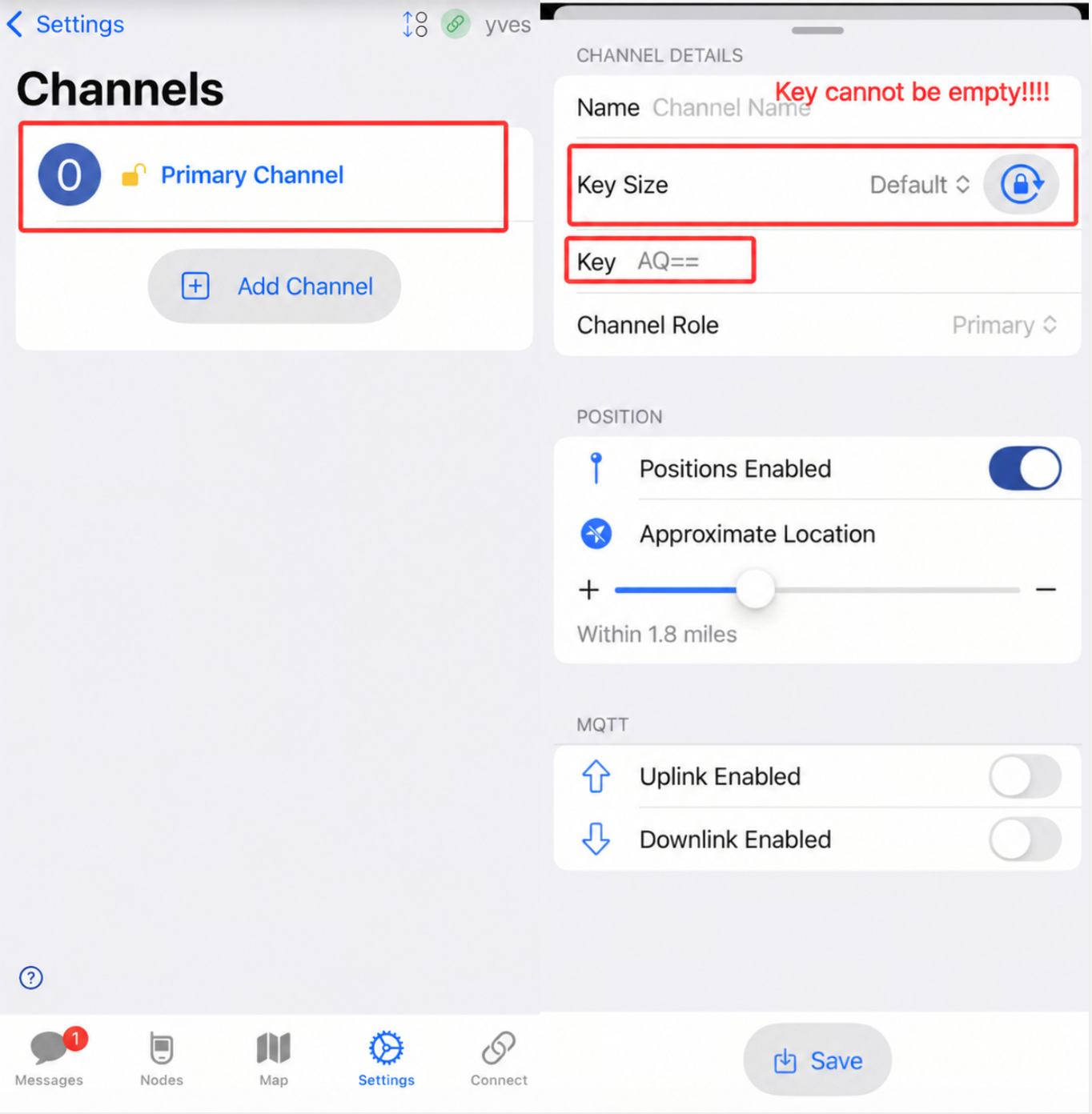
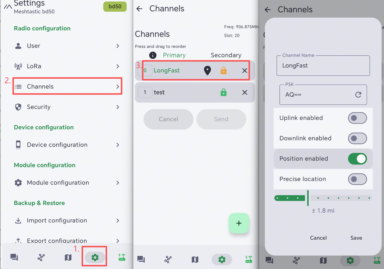
If the device cannot communicate with nearby nodes or send messages, first check that the LoRa region and modem preset match the surrounding nodes. You should also check whether the default PSK has been changed. A different PSK on the primary channel will prevent the device from communicating with other nodes on that channel.
The easiest way to find this issue is through the mobile app. Open the app, connect to the target device, then navigate to Settings -> Channels. Select the primary channel and check the PSK value. If it is different from the surrounding nodes, update it to the same PSK and save the channel settings.
- IOS App
- Android App
Solution
If you are not sure which settings were changed, restore the device to its default settings by following the Factory Reset guide. If only the PSK was changed, set it back to AQ==.
Device automatically turns off
Description
- After the device turns on, it turns off or reboots automatically after a while.
- The serial port log ran for a while and then stopped.
This may be caused by manually and forcibly rebooting or turning off the device while it is in one of the following states: not finishing the message transmission process or being configured.
Troubleshoot
Click here to perform a flash erase, and then re-flash the latest firmware.
Factory Reset
If you want to restore the default settings, you can perform a factory reset. There are two methods for doing the factory reset.
-
Click here to perform a flash erase, and then re-flash the latest firmware.
-
Click the
Factory Resetbutton in the app. The device will automatically reboot with the factory configuration.
Direct Message Fail
NodeDB Reset
NodeDB is the local database that stores information about nodes discovered in the current Mesh network. If you encounter a situation where you can't communicate with a certain node, it might be because your nodedB has stored outdated information for that node. You will need to update it.
NodeDB stores details such as:
- Node ID
- User name
- Location information
- Signal information (SNR)
- Last seen time
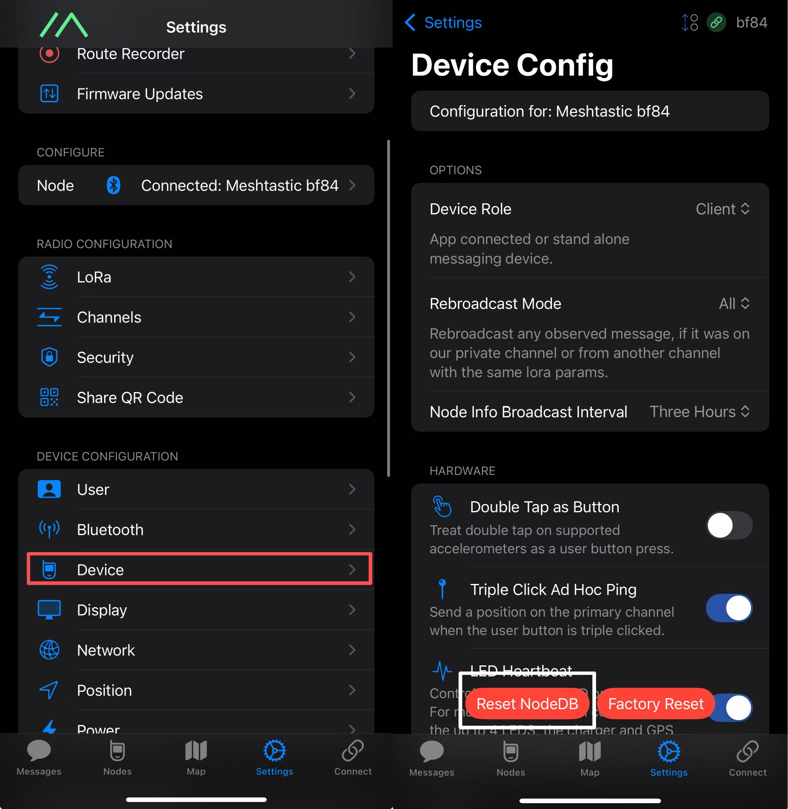
Open the app and connect to the target device. Go to Settings->Device->Device Config->Reset NodeDB.
Exchange User Info
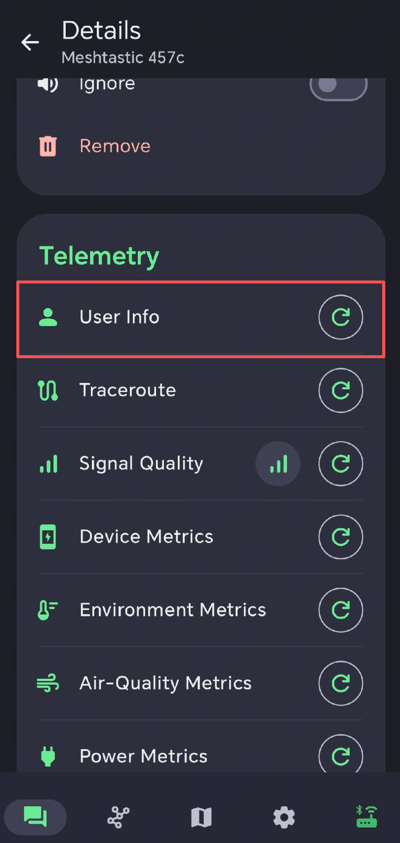
Each node will periodically send its own node information, enabling other nodes in the mesh to "see" and "recognize" it. Two nodes need to exchange their node information with each other in order to be able to communicate with each other. If you are unable to send or receive private messages with another node on the list, you can manually prompt them to exchange information in the app.
Regenerate Private Key
Each node owns a public/private key pair. To exchange an encrypted private message, the sender encrypts it with the recipient's public key, and only that recipient's private key can decrypt it. Two nodes can therefore communicate privately once they know each other's public key. If one node keeps failing in private-message transmission, try regenerating its private key. After regeneration, delete that node from the other devices' node lists so they can reconnect and obtain its new public key.
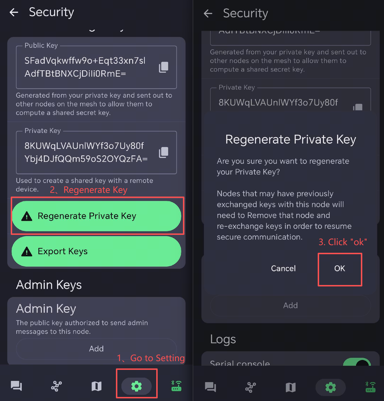
Reboot the faulty device to make the configuration function.
After the key regeneration, other device needs to reconnect with the node. So it is better to delete the node in other device's node list.
Please note the difference between the following options:
- Reset NodeDB: Only clears the node database.
- Factory Reset: Restores the device to factory settings and removes additional configuration data.
Power Consumption
Power consumption primarily depends on factors such as the data transmission frequency and GPS update rate. The figures below are for reference only; actual consumption may vary based on real-world usage conditions.
- Shutdown sleep mode power consumption
| Description | Consumption |
|---|---|
| GPS_LED working current | 1.02 mA |
| Powered but not activated | 56.195 μA |
| Powered and activated | 611 μA |
Example:
| Battery capacity | Battery life |
|---|---|
| 3350 | 136.8 |
| 12000 | 490.2 |
- Active mode power consumption
| Mode | Current |
|---|---|
| Static Current | 10.65 mA |
| EU868 Transmission Current | 157.74 mA |
| US915 Transmission Current | 205.22 mA |
| GPS Operating Current | 50 mA |
| GPS_LED Operating Current | 1.02 mA |
Signal Quality
-
SNR reflects the quality of the communication link. A normal device usually operates above -7 dB. A device with an SNR lower than -10 dB indicates poor performance.
-
RSSI is determined jointly by the device and its surrounding environment. A normal device usually operates above -110 dBm. A device with an RSSI lower than -115 dBm is considered to have poor performance.
To achieve the best signal performance, please use the device in an open, unobstructed area with minimal interference.
Charging Current

The Xiao nRF-52840 Plus maximum charging current is 200 mA. The CN3165 charging management chip supports 0.99 A. Therefore, the maximum charging current is 1 A.
Resource
Tech Support & Product Discussion