Get Started with Meshtastic
The Wio Tracker L1 Series share the same hardware framework. Although the video guide was for the L1 Pro, it is applicable to all other products in the L1 series.
Video Tutorial
Part 1 Unboxing
When using the L1, L1 Lite or L1 E-Ink models for the first time, after connecting to USB power supply, lift the power switch upwards to turn it on.
Part 2 Firmware Flashing
Please don't use NRF-OTA to update the firmware, it may cause the device to be completely dead.
Part 3 Device Usage
Four-way Joystick
The latest Alpha firmware of L1 E-Ink firmware currently supports the four-way joystick. If you want to use the joystick, please click here to upgarde the firmware.
Menu Bar
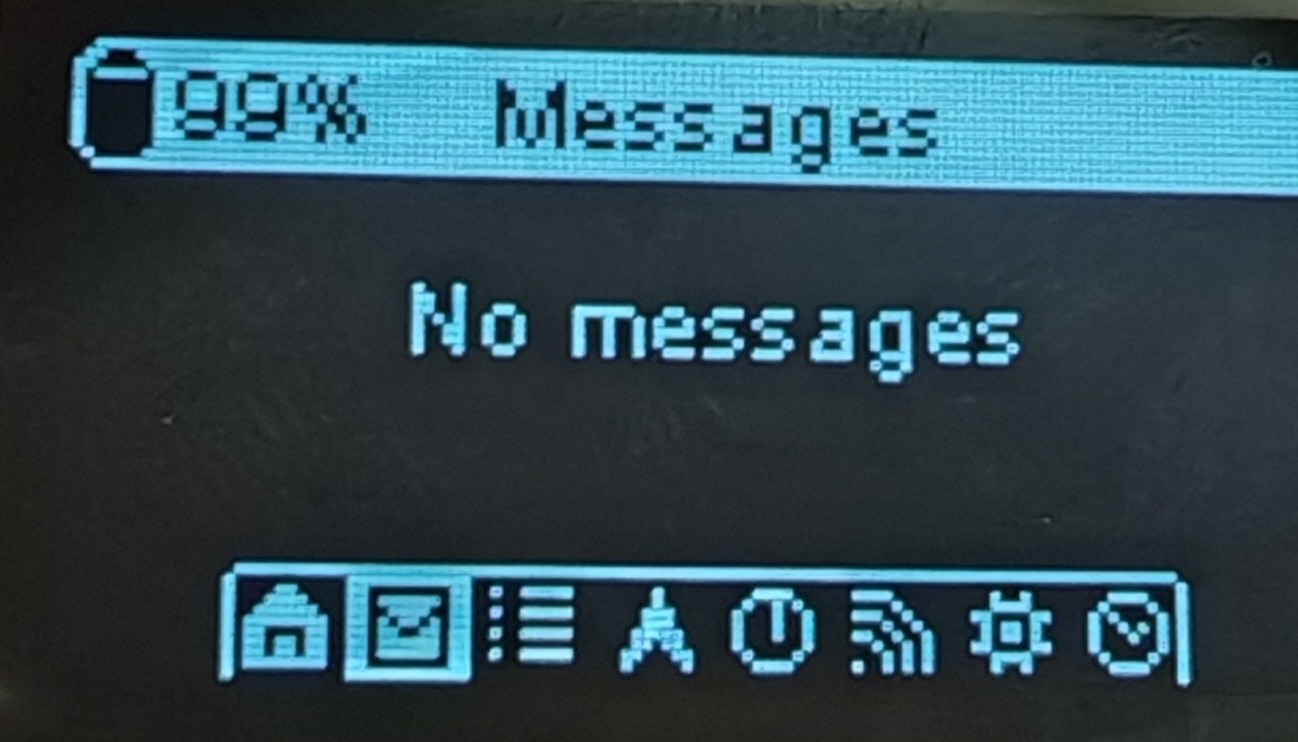
Only the 2.7 firmware support the menu bar. If you want to use the menu bar, follow the Flash Firmware Tutorial to update firmware.
Buzzer
If you want to turn on or off the buzzer, please first update the firmware to 2.7 version. Because only the 2.7 version firmware has the menu bar.
- Turn on the buzzer Setting (icon shaped like the gear) -> Notification -> Buzzer Action -> Disable
- Turn off the buzzer Setting (icon shaped like the gear) -> Notification -> Buzzer Action -> All enabled
Part 4 Phone Connection
Part 5 Different States
Get Started
When the device is in the states below, please don't manually reboot or turn off it. Or else the device can be dead.
- Not finishing the message transmission process
- Being configured
Flash Firmware
Please don't use NRF-OTA to update the firmware, it may cause the device to be completely dead.
Visit Meshtastic Web Flasher.
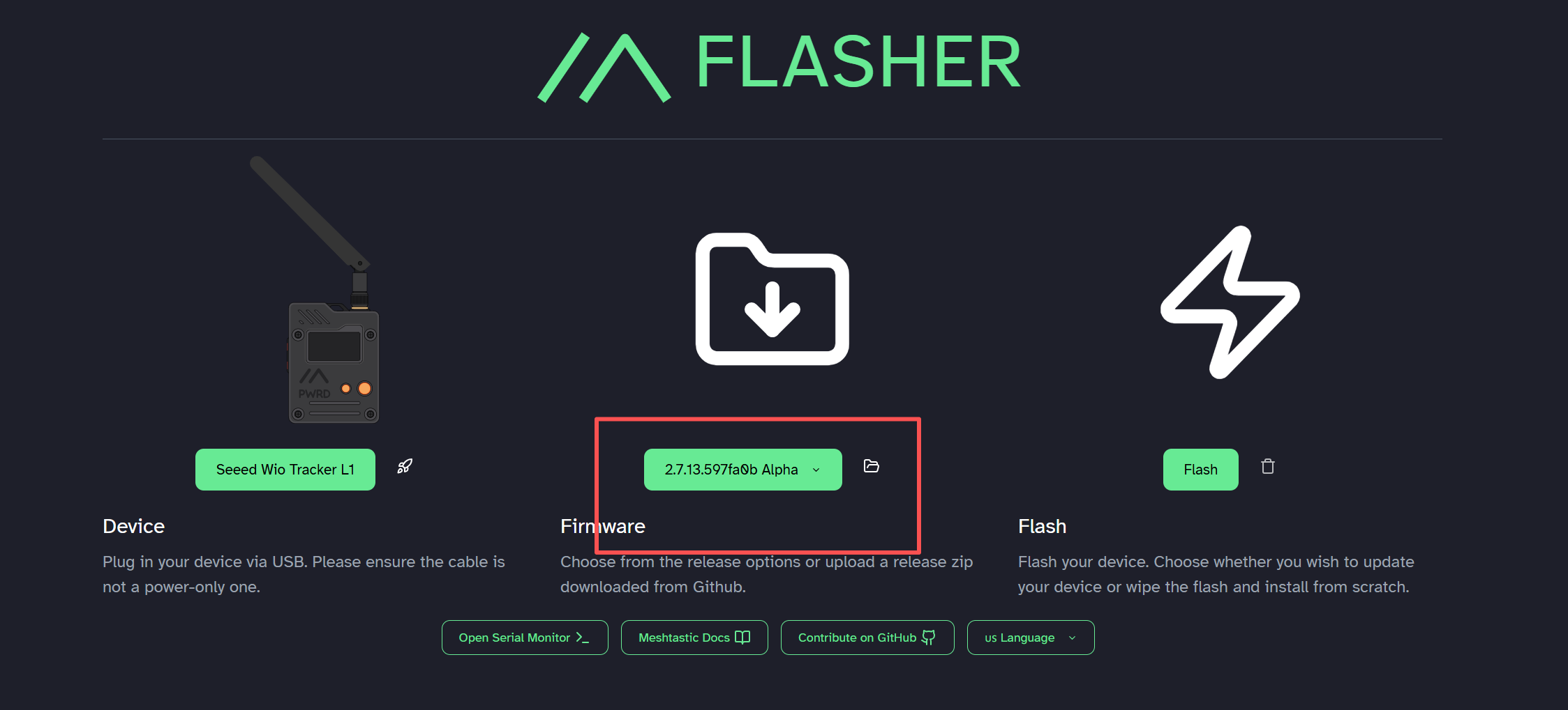
For L1, L1 Lite and L1 Pro, select the target device to Seeed Wio Tracker L1 and choose the latest firmware, then click Flash.


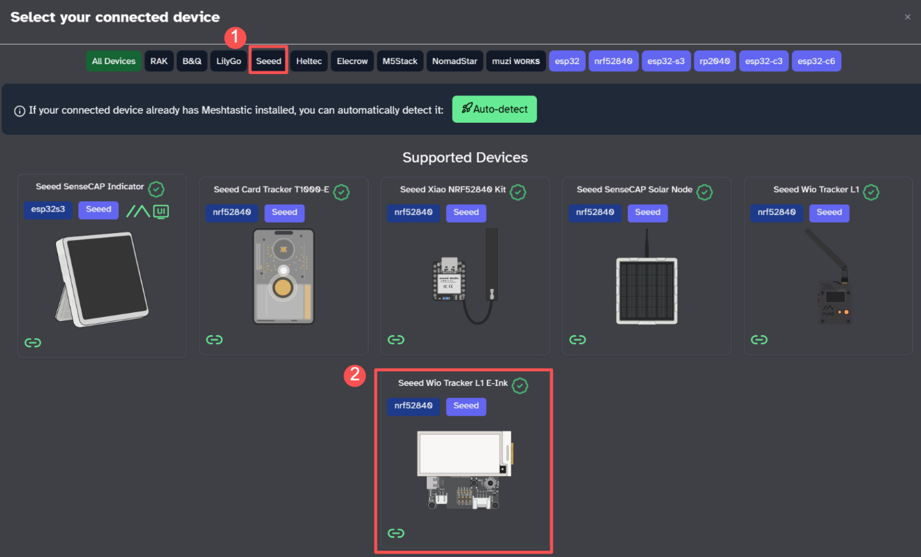
For L1 E-Ink, select the target device to Seeed Wio Tracker L1 E-Ink and choose the latest firmware, then click Flash.
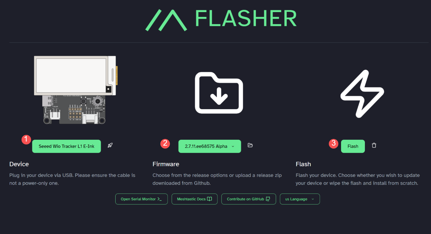
Switch on the device, click Enter DFU Mode, there will be a serial port named Tracker L1, click and connect it, and there should be a driver named Tracker L1 display.

Drag the UF2 file to the DFU drive. Firmware should be flashed after the file is downloaded and the device reboots.
Power on the device
Connect the USB cable to activate the device. Lift the power switch upwards to turn it on.
If the device doesn't respond when you press the button, please charge it first. Do not use the fast-charging charger.
Connect via App
- IOS App
- Android App
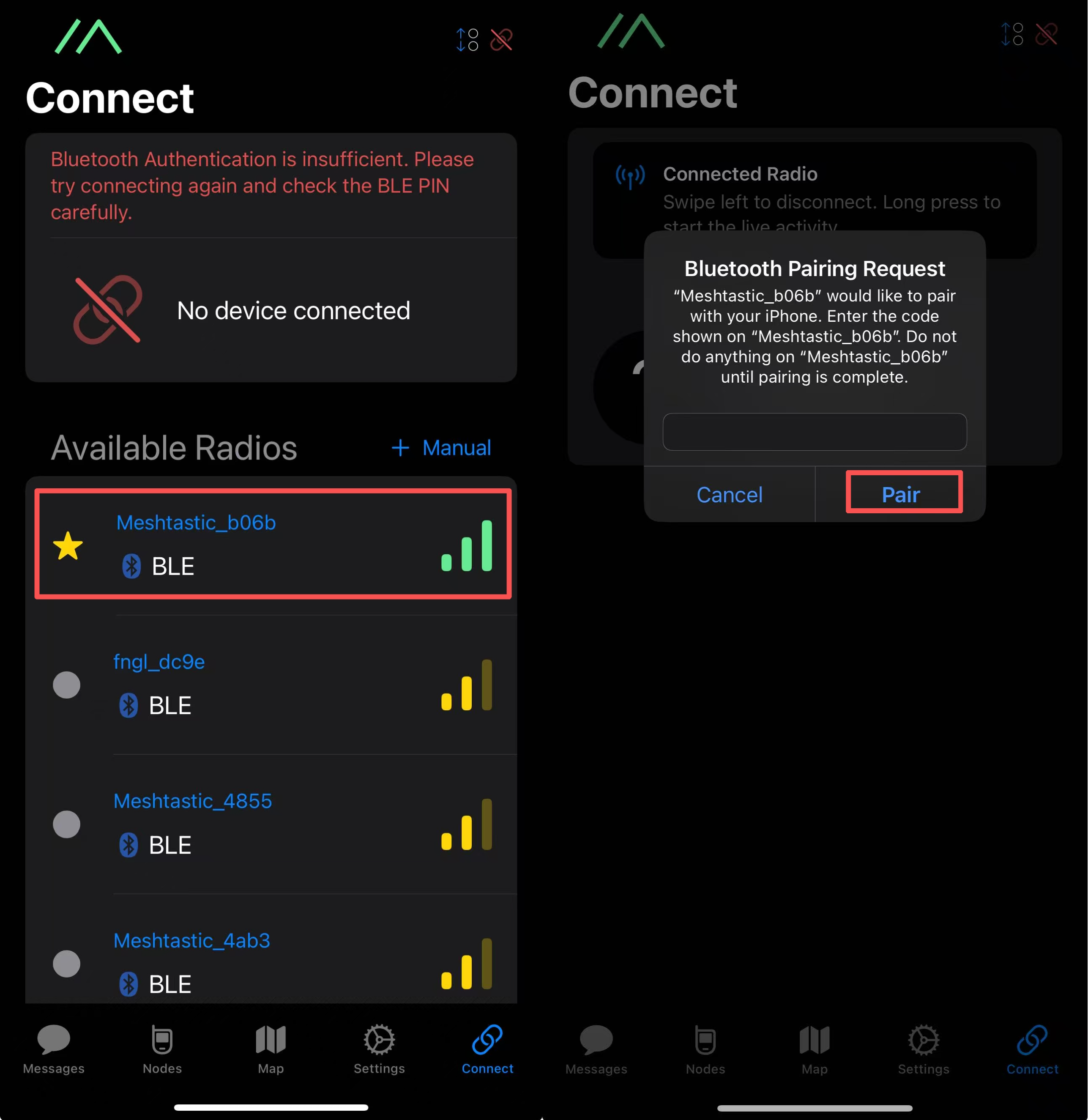
- Select the target device on the Bluetooth panel.
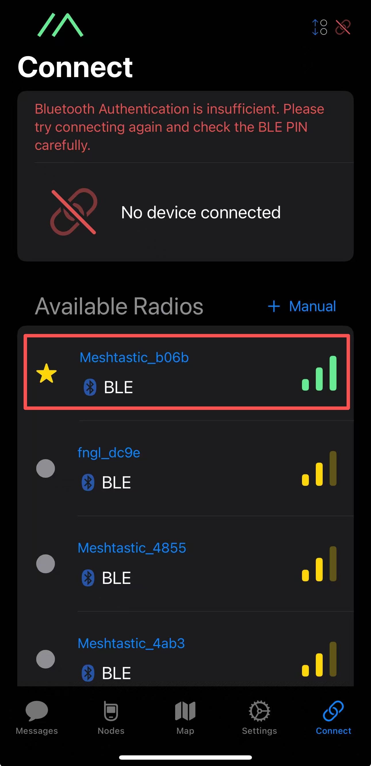
- Enter the code on the display and then click
OKto connect the device.
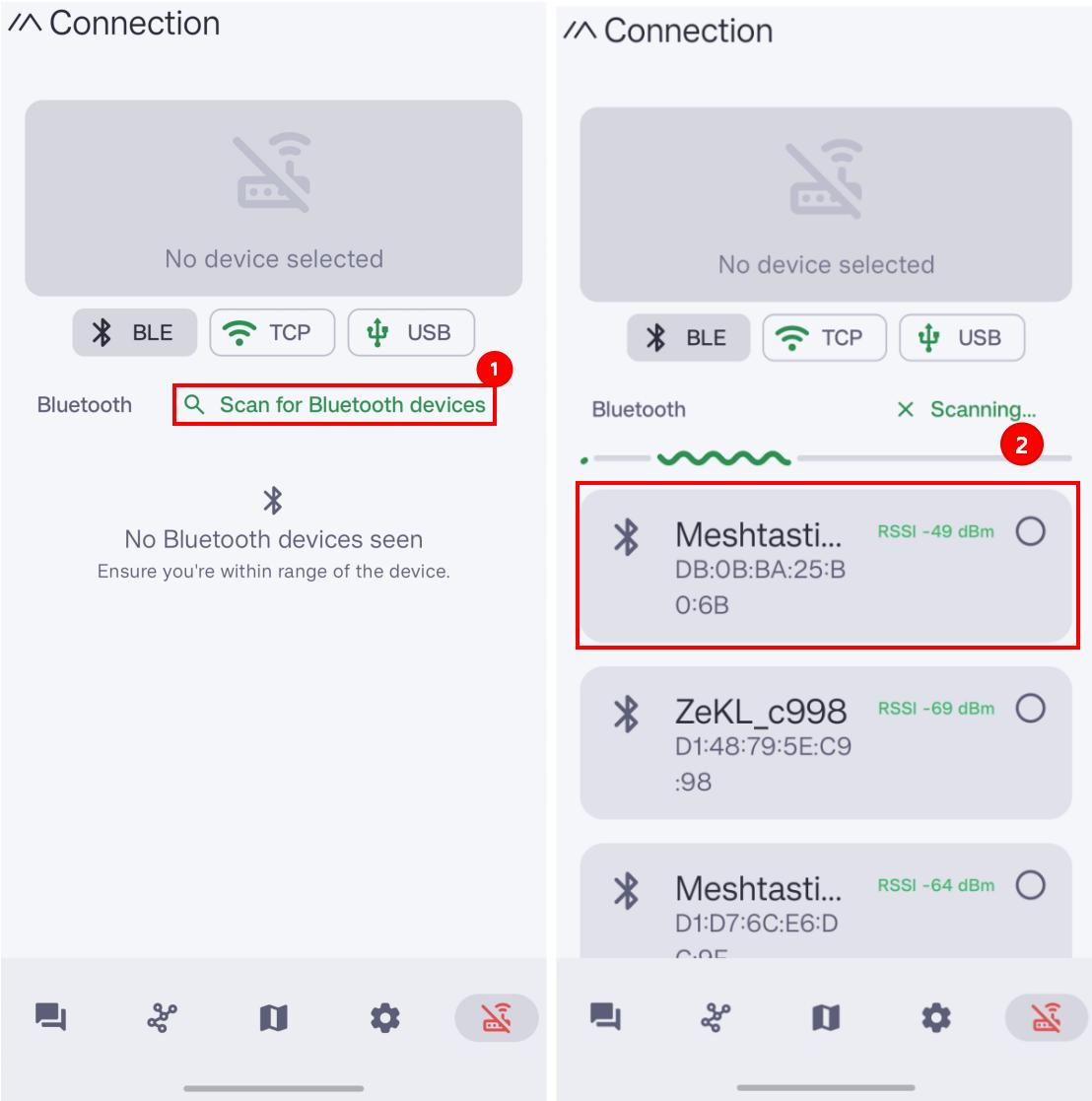
- Click
+and choose the target device.
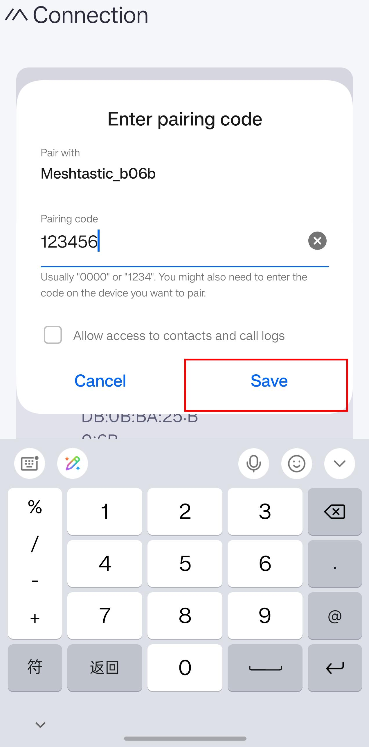
- Enter the code(default code is
123456) and then clickOKto connect the device.
Configure the LoRa
In order to start communicating over the mesh, you must set your region. This setting controls which frequency range your device uses and should be set according to your regional location.
- IOS App
- Android App
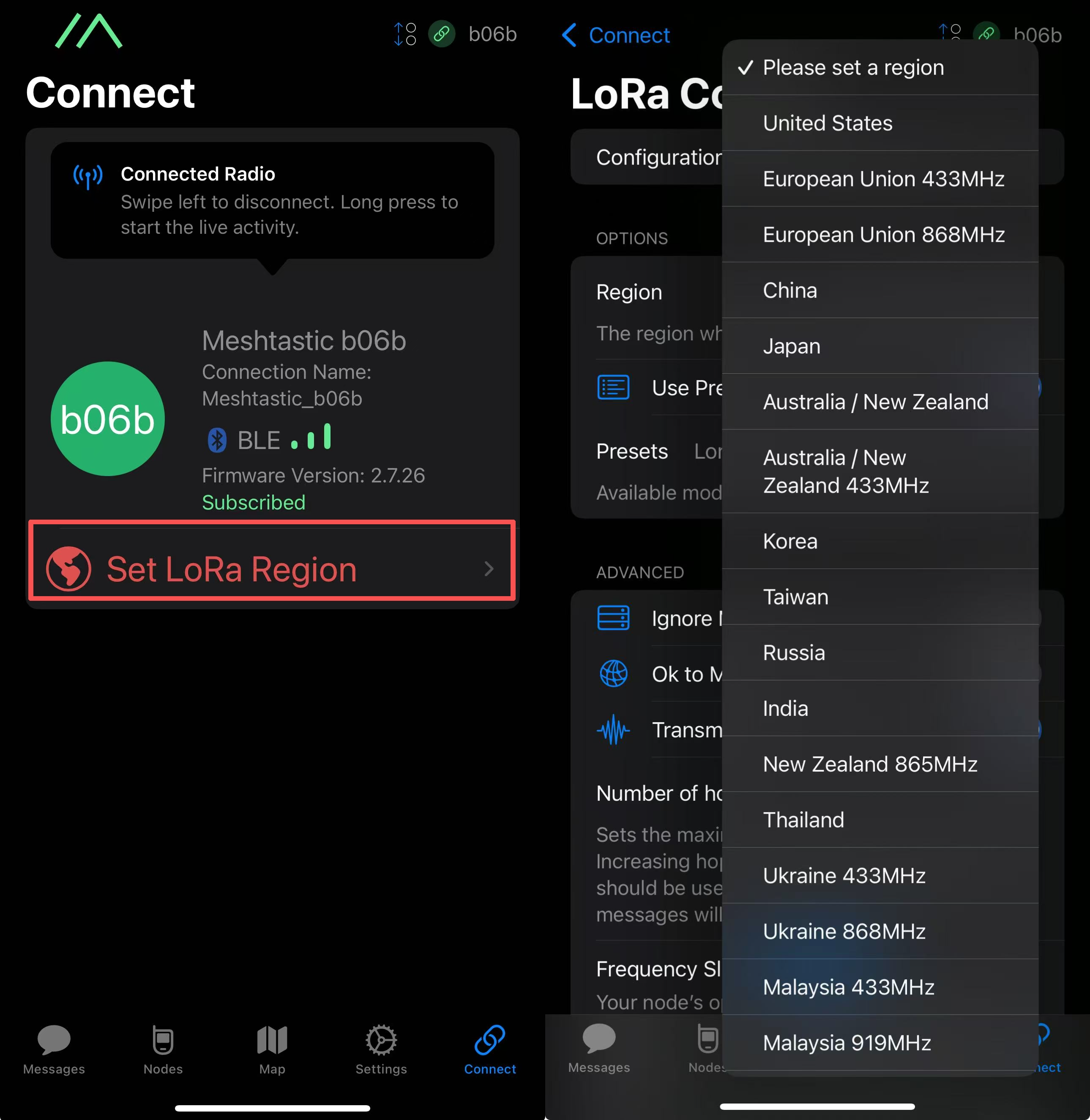
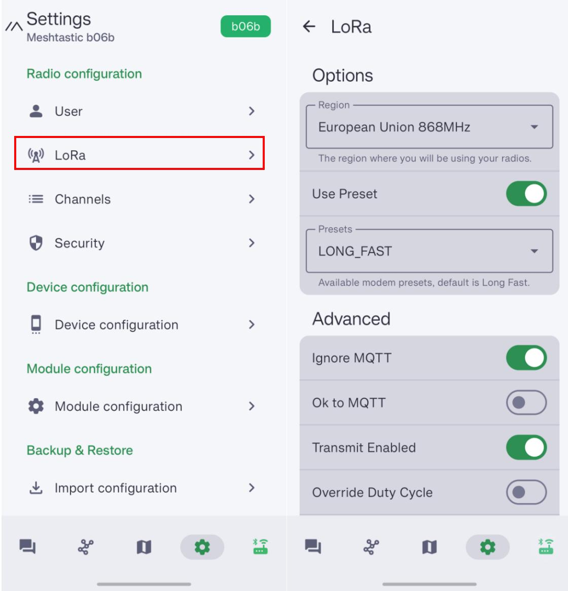
Region List
| Region Code | Description | Frequency Range (MHz) | Duty Cycle (%) | Power Limit (dBm) |
|---|---|---|---|---|
| UNSET | Unset | N/A | N/A | N/A |
| US | United States | 902.0 - 928.0 | 100 | 30 |
| EU_868 | European Union 868MHz | 869.4 - 869.65 | 10 | 27 |
Refer to LoRa Region by Country for a more comprehensive list.
EU_868 has to adhere to an hourly duty cycle limitation of 10%, calculated every minute on a rolling 1-hour basis. Your device will stop transmitting if you reach it, until it is allowed again.
Now that you have set the LoRa region on your device, you can continue with configuring any LoRa Configs to suit your needs.
Advanced Configuration
Connect via Website
If you want to text messages and communicate with other nodes in the website, you can connect the device to the Meshtastic Website now.
Step 1: Open the Website
Click here to go to the webstite.

Step 2: Add the new device
Click "+ New Connection".

There are two ways to connect. You can choose your preferred method.
Method 1: Via Bluetooth
Choose bluetooth method. Choose the device ID in the pop-up window.

Method 2: Via Serial
Choose serial method. Open the device manager to see which port the device is connected to. Choose that port in the pop-up window.

Your device will be shown in the list. Click to connect. If the connection succeed, you can see the device status directly on the website.

Configure GPS
Please set GPS enabled. You can adjust the update inerval and broadcast interval to obtain a more up-to-date location information.

For IOS, please turn on the Accurate Location. Otherwise, the positioning may deviate.

Sensor connection
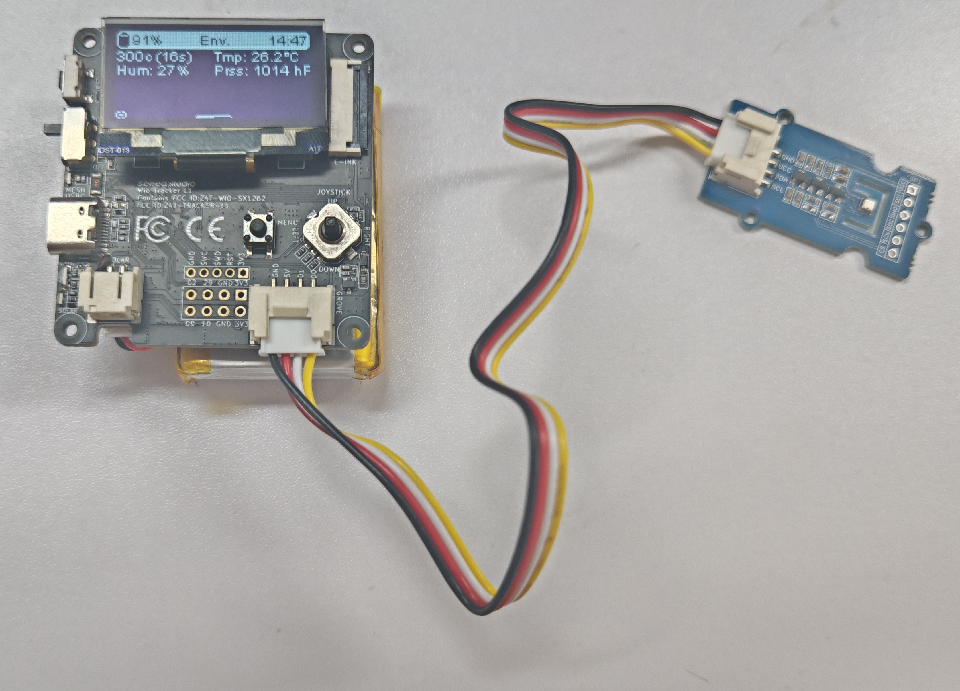
You can add sensor to the device via the grove interface. The following sensors have been verified to be compatible with the Grove interface on the device.
| Sensor type | Sensor Model | |
|---|---|---|
| Environmental Sensor | Pressure | BMP085 |
| Temperature | MCP9808 、PCT2075 | |
| Temperature & Humidity | SHT31/SHTC3/SHT4X、AHT10 | |
| Temperature & Humidity & Pressure | BME280 | |
| Other | Heart Rate & SpO₂ | MAX30102 |
| I2C Keyboard | CardKB | |
- IOS
- Android
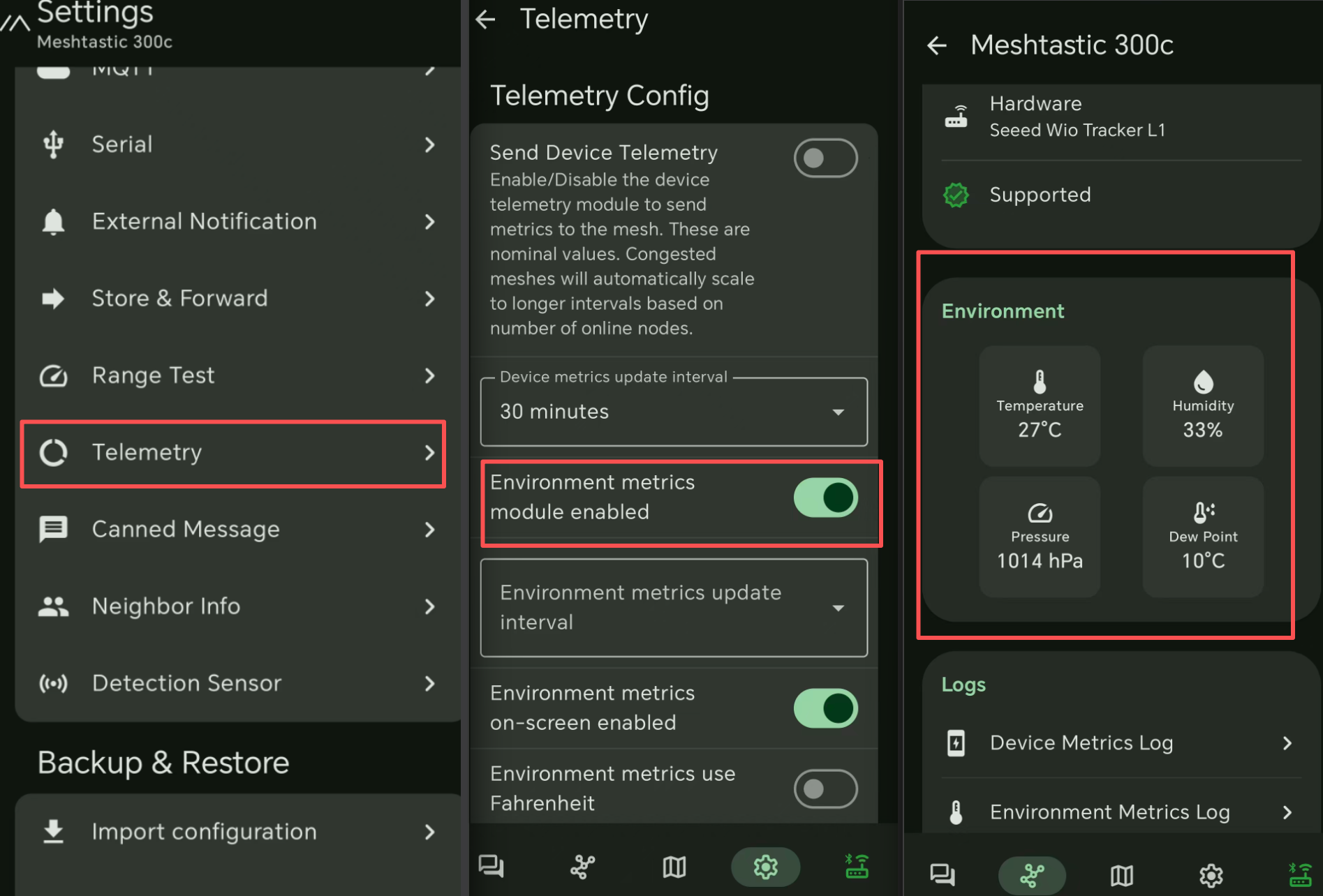
- Enable Telemetry to get sensor data. If you want to show sensor data on the OLED screen, enale
on screen
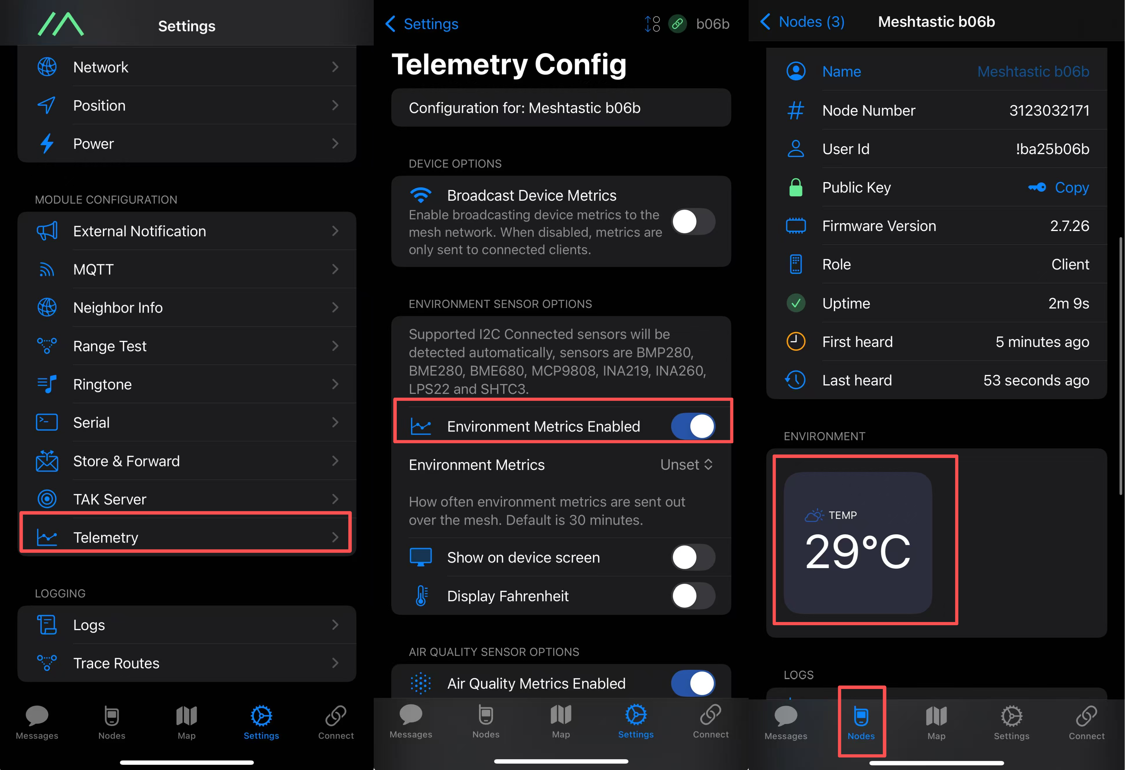
- Enable Telemetry to get sensor data. If you want to show sensor data on the OLED screen, enale
on screen
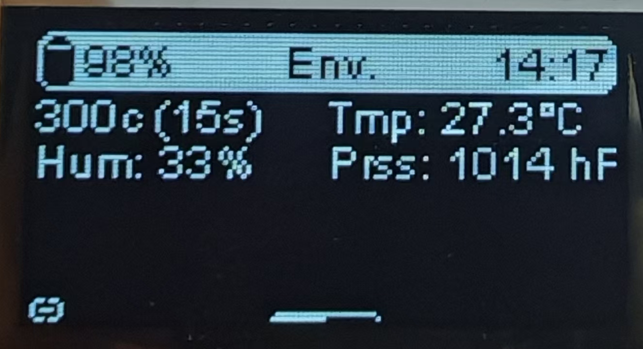
The OLED will show sensor data if you enable on screen.
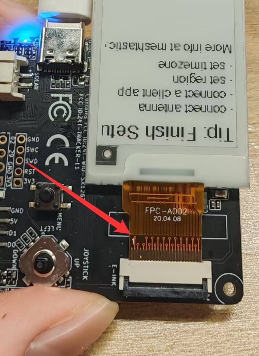
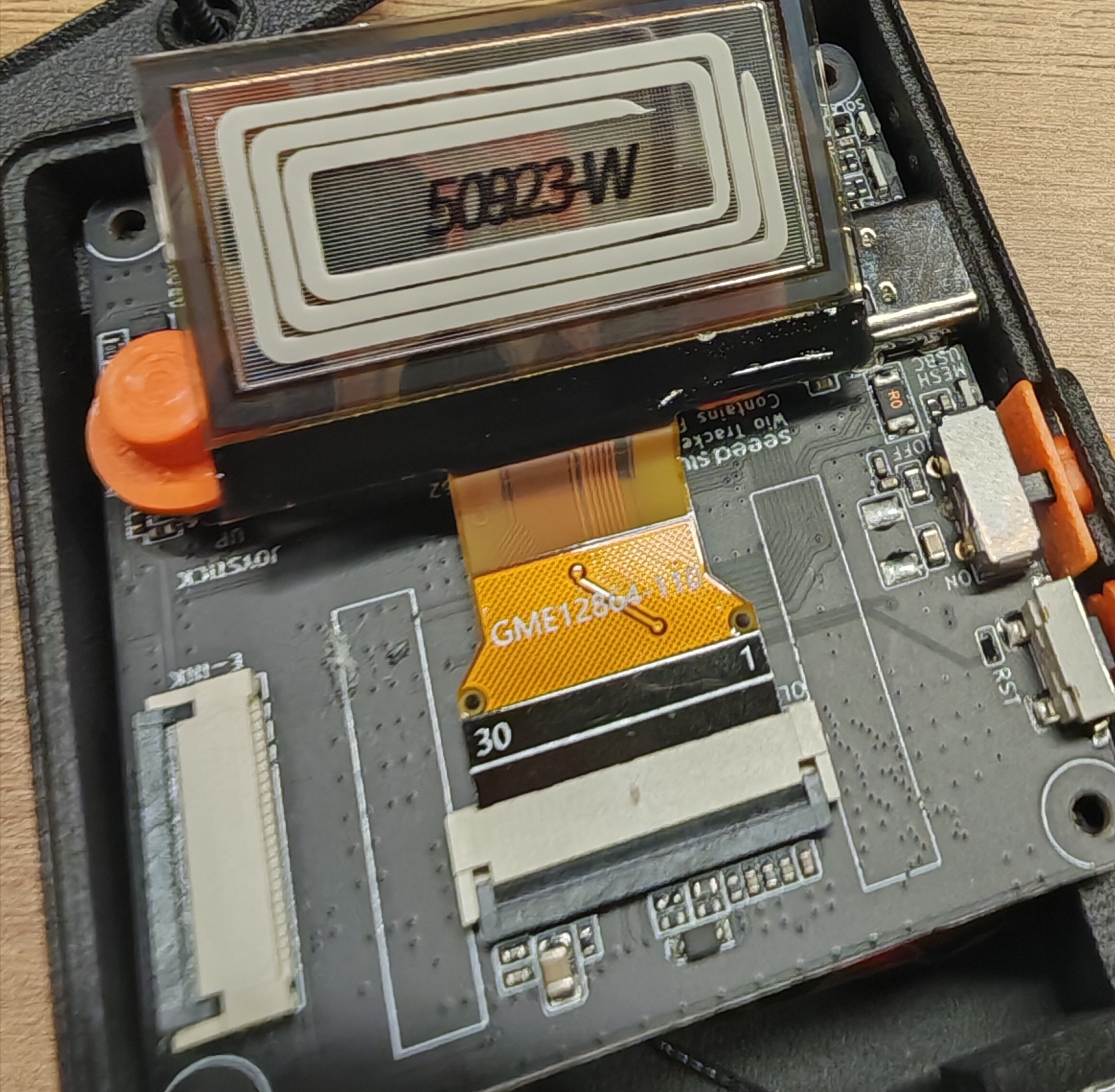
Screen Connection
- E-Ink Screen Click here to get the compatible E-Ink screen.
- OLED Screen Click here to get the compatible OLED screen. The current OLED driver is SSD1306.
Virtual Keyboard
The 2.7 version firmware now support virtual keyboard! You can type message directly on the device to communicate with other device. Follow the Flash Firmware Tutorial to update firmware.
Configure Ringtone
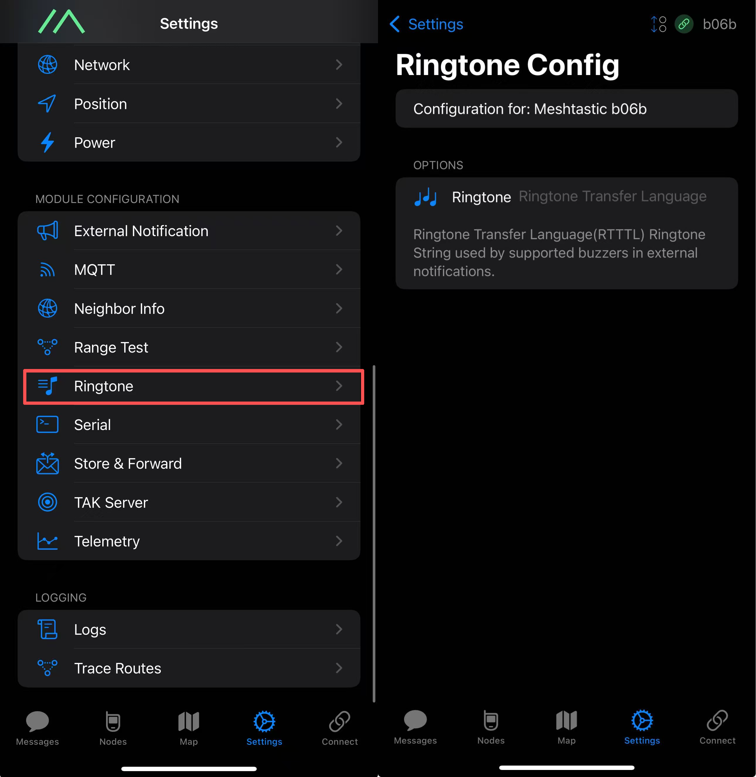
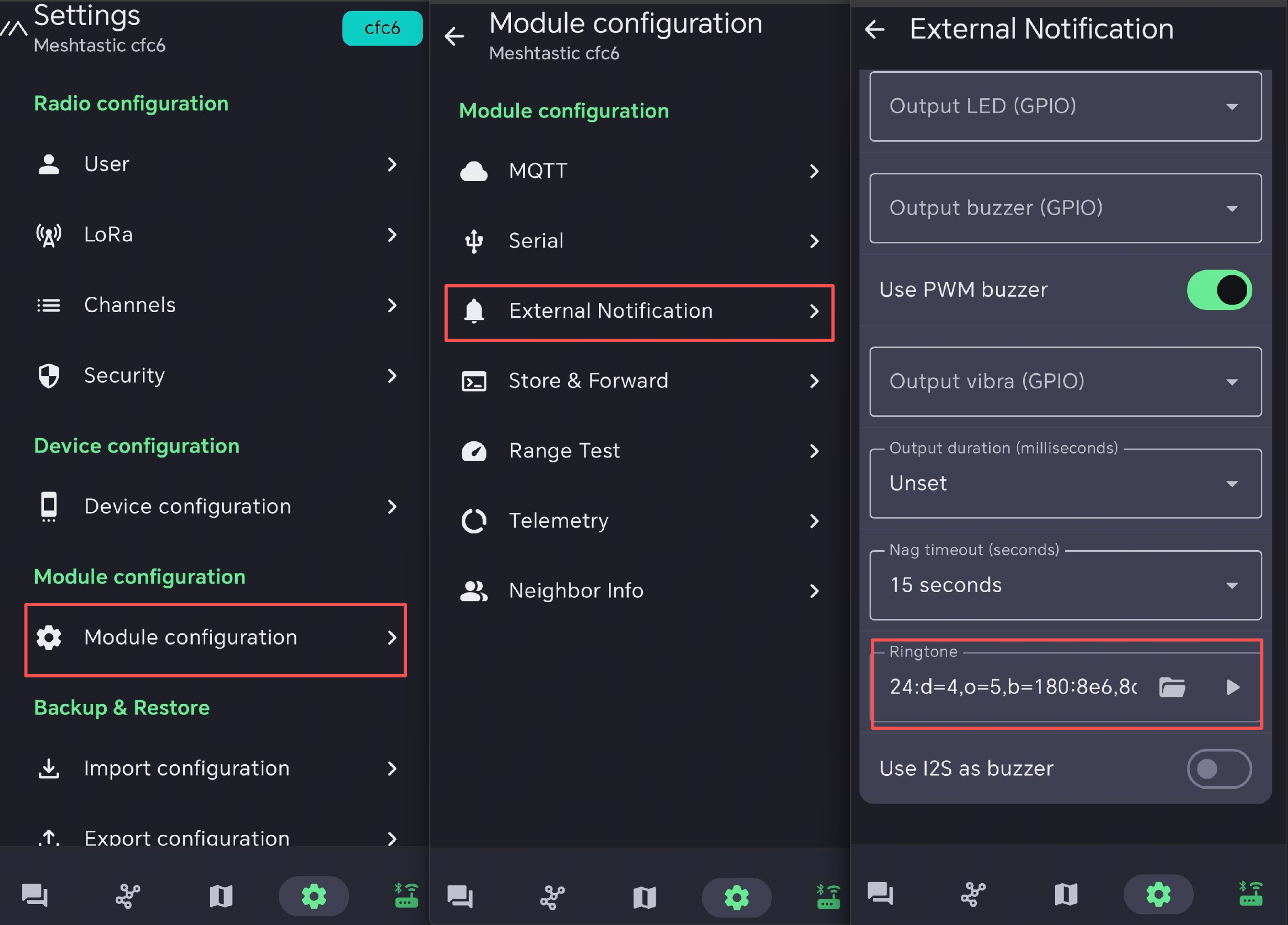
Navigate to Settings -> Ringtone Config, then enter the RTTTL ringtone string you want to use for external notifications.
- IOS App
- Android App
- The Legend of Zelda: Item Get
- Super Mario Theme (Short)
- Mario Coin
- Nokia Ringtone
- Mario Power-Up
- Morse Code CQ
24:d=16,o=5,b=120:g,c6,d6,2g6
24:d=4,o=5,b=100:16e6,16e6,32p,8e6,16c6,8e6,8g6,8p,8g
24:d=8,o=6,b=200:b,e7
24:d=4,o=5,b=180:8e6,8d6,f#,g#,8c#6,8b,d,e,8b,8a,c#,e,2a
powerup:d=16,o=5,b=200:g,a,b,c6,d6,e6,f#6,g6,a6,b6,2c7
24:d=16,o=6,b=120:8c,p,c,p,8c,p,c,4p,8c,p,8c,p,c,p,8c,8p
FAQ
Device Bricked & Bootloader Recovery
Description:
The device is not responding, no LED, can not pair with your App. If you found the device completely dead after flashing your own firmware, you can try re-install the bootloader too.
The bootloader is restored over the USB serial port (Serial DFU) with adafruit-nrfutil.
During flashing, keep the cable connection stable and DO NOT disconnect it — even if the serial port number changes.
Step 1: Prepare
- A Wio Tracker L1 series device (L1 / L1 Pro)
- A known-good USB data cable (not a charge-only cable)
- A Windows, macOS or Linux PC with Python 3 and pip
- The bootloader package: Click here to download Bootloader — do NOT extract the ZIP;
adafruit-nrfutiluses it as it is
Step 2: Install adafruit-nrfutil
- Windows
- macOS
- Linux
Check that Python 3 and pip are available (if pip is missing, run python -m ensurepip --upgrade first):
python --version
python -m pip --version

Then install and verify (the version tested for this guide is 0.5.3.post16):
python -m pip install --user adafruit-nrfutil
adafruit-nrfutil version

python3 --version
python3 -m pip install --user adafruit-nrfutil
adafruit-nrfutil version
If pip is missing, run python3 -m ensurepip --upgrade first.
On Ubuntu/Debian, install adafruit-nrfutil with pipx. It isolates the tool from the system Python environment and avoids the externally-managed-environment error:
sudo apt update
sudo apt install pipx
pipx install adafruit-nrfutil
pipx ensurepath
On Fedora, use sudo dnf install pipx instead of apt. Reopen your terminal, then verify:
adafruit-nrfutil version
Always check the version with adafruit-nrfutil version. Do NOT use adafruit-nrfutil --version.
Step 3: Check the serial port
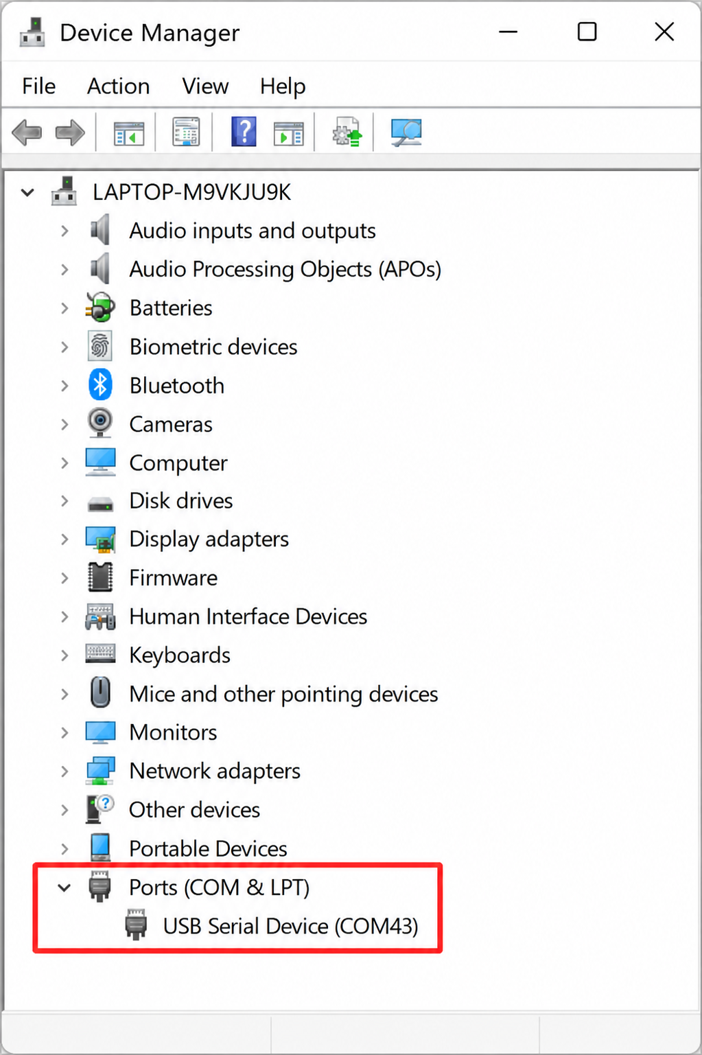
Note the device’s serial port — the examples below vary by PC:
- Windows
- macOS
- Linux
Open Device Manager → Ports (COM & LPT), for example:
USB Serial Device (COM43)
ls /dev/cu.*
The device appears as /dev/cu.usbmodemXXXX.
ls /dev/ttyACM*
The device usually appears as /dev/ttyACM0; if nothing is listed, also try ls /dev/ttyUSB*. Compare the results before and after connecting the device to identify its port. Check again after entering DFU mode, because the port number may change.
Check the port permissions, replacing /dev/ttyACM0 with your actual port:
ls -l /dev/ttyACM0
On Ubuntu/Debian, serial ports usually belong to the dialout group. If you get Permission denied and the port belongs to dialout, add your user to that group:
sudo usermod -aG dialout "$USER"
Log out and log back in for the change to take effect. On other distributions, use the serial-access group shown by ls -l and follow your distribution's instructions.
Step 4: Flash the bootloader
Replace the port with the one you found in Step 3:
Close any serial monitor or browser flasher connected to the device. If you have already entered DFU mode by double-pressing Reset, use the current DFU port and omit --touch 1200 from the commands below.
- Windows
- macOS
- Linux
adafruit-nrfutil --verbose dfu serial --package "wio_tracker_l1_bootloader-0.10.0_s140_7.3.0.zip" -p COM43 -b 115200 --singlebank --touch 1200
If the ZIP is not in your terminal’s current folder, pass its full path to --package, e.g. "C:\path\to\wio_tracker_l1_bootloader-0.10.0_s140_7.3.0.zip".
adafruit-nrfutil --verbose dfu serial --package "wio_tracker_l1_bootloader-0.10.0_s140_7.3.0.zip" -p /dev/cu.usbmodemXXXX -b 115200 --singlebank --touch 1200
adafruit-nrfutil --verbose dfu serial --package "wio_tracker_l1_bootloader-0.10.0_s140_7.3.0.zip" -p /dev/ttyACM0 -b 115200 --singlebank --touch 1200
Step 5: Handle the serial port change
--touch 1200 requests DFU mode by opening and closing the serial port at 1200 baud. The operating system may then assign a different port, and the first command may stop with a traceback like this:
Touched serial port COM43
...
FileNotFoundError: could not open port 'COM43'
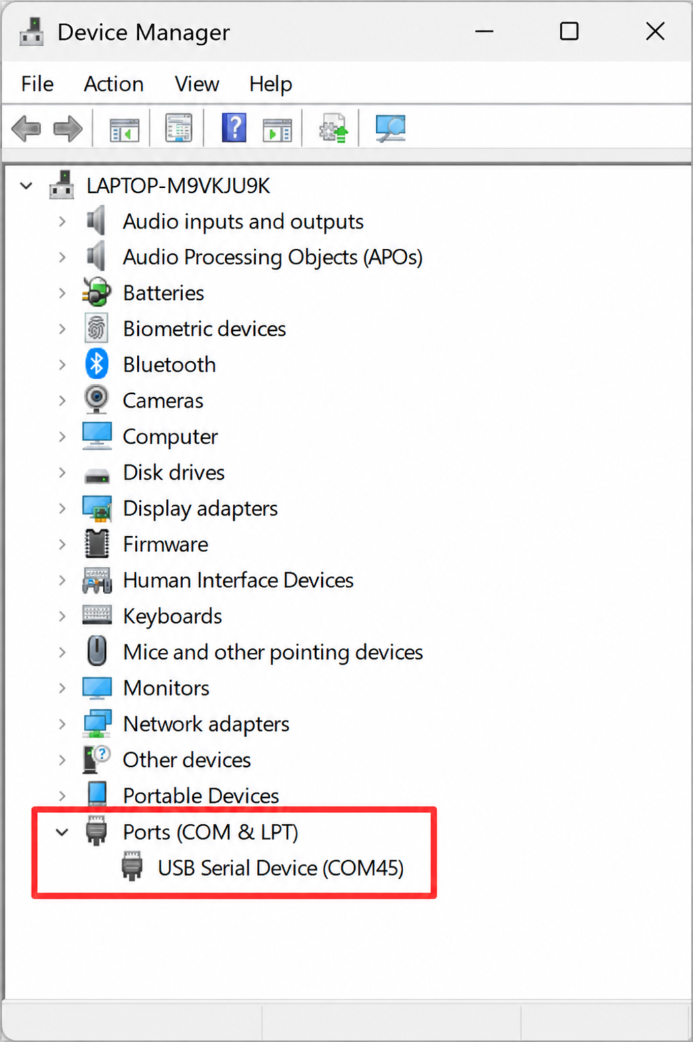
Check whether a new DFU port has appeared before retrying. This error alone does not confirm that the device entered DFU mode or that the bootloader was flashed successfully. On the tested Windows PC, the port changed from COM43 to COM45:
Keep the USB cable connected. Find the new port (refresh Device Manager → Ports (COM & LPT), or re-run ls /dev/cu.* / ls /dev/ttyACM*), then flash again on the new port WITHOUT --touch 1200:
- Windows
- macOS
- Linux
adafruit-nrfutil --verbose dfu serial --package "wio_tracker_l1_bootloader-0.10.0_s140_7.3.0.zip" -p COM45 -b 115200 --singlebank
adafruit-nrfutil --verbose dfu serial --package "wio_tracker_l1_bootloader-0.10.0_s140_7.3.0.zip" -p /dev/cu.usbmodemXXXX -b 115200 --singlebank
For example, if the new DFU port is /dev/ttyACM1, use the following command. Replace it with your actual port:
adafruit-nrfutil --verbose dfu serial --package "wio_tracker_l1_bootloader-0.10.0_s140_7.3.0.zip" -p /dev/ttyACM1 -b 115200 --singlebank
Step 6: Confirm the result
The flashing succeeded when the output ends with Device programmed.:
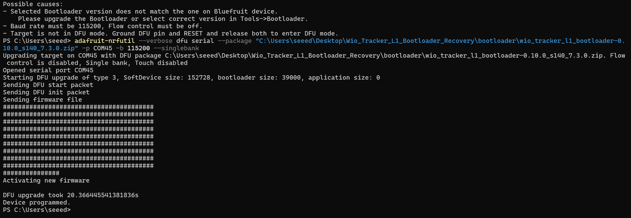
After that, a UF2 drive appears on your PC (screenshot from the tested Windows PC). Its volume label varies with the bootloader build — the tested unit showed XIAO-BOOT — and is NOT a pass/fail criterion; do not judge the result by the drive name or by INFO_UF2.TXT:
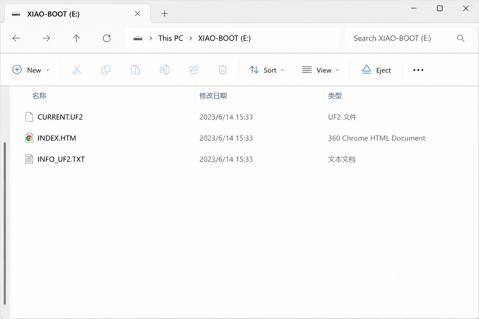
Step 7: Reinstall the application firmware
Restoring the bootloader does NOT reinstall the application firmware — the device still has no working firmware until you flash it again.
When you have completed the above steps, follow Flash Firmware to flash the application firmware.
Troubleshooting
adafruit-nrfutilis not recognized after installation: add the Python user scripts directory to your PATH (Scriptson Windows,binunder your home directory on macOS); on Linux, reopen your terminal afterpipx ensurepath.- Port busy / access denied: close serial monitors, web flasher tabs, Arduino IDE, or anything else holding the port. On Linux, also check the serial port permissions and group membership as described in Step 3.
FileNotFoundError: could not open port ...afterTouched serial port ...: check whether a new DFU port appeared and follow Step 5. If no DFU port appears, try the manual DFU recovery below.- Unable to enter DFU mode: see Unable to enter DFU & Entering DFU Mode Manually.
Manual DFU recovery
If --touch 1200 cannot put the device into DFU mode (e.g. the firmware is completely unresponsive), enter it by hand: connect the device, double-press Reset (the yellow LED stays solid), find the DFU serial port as in Step 3, then run the Step 5 command on that port WITHOUT --touch 1200. Success looks the same as Step 6.
Unable to enter DFU & Entering DFU Mode Manually
Connect the device to your PC and double-press the Reset button — the yellow LED stays solid and a DFU serial port appears on your PC.
To flash the bootloader in this mode, follow Device Bricked & Bootloader Recovery, but skip --touch 1200 — the device is already in DFU mode.
Exiting DFU Mode
Press the Reset button once to exit DFU mode.
Unable to Communicate on the Primary Channel
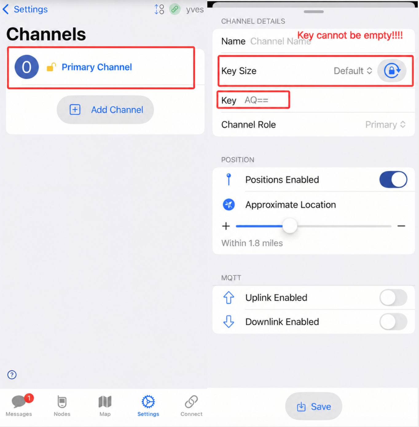
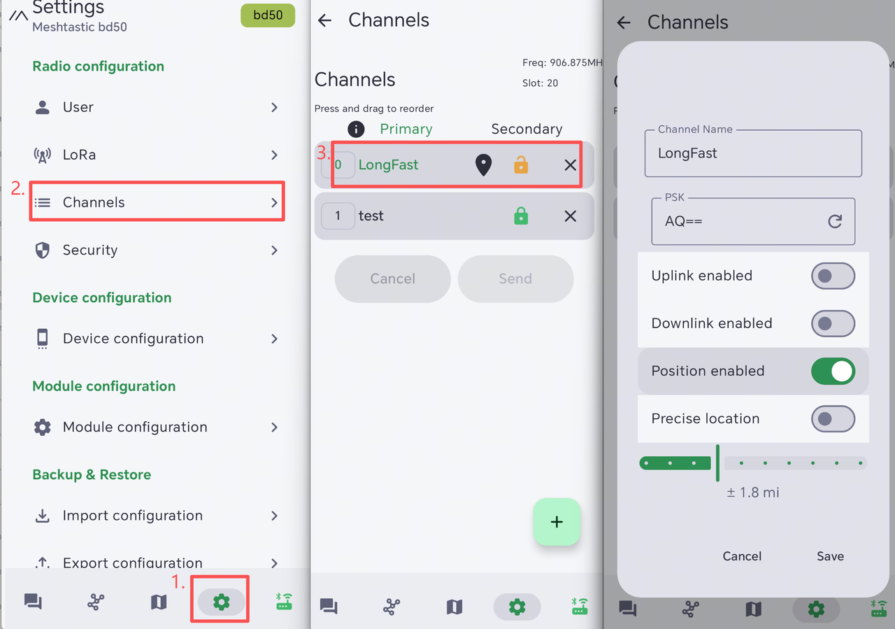
If the device cannot communicate with nearby nodes or send messages, first check that the LoRa region and modem preset match the surrounding nodes. You should also check whether the default PSK has been changed. A different PSK on the primary channel will prevent the device from communicating with other nodes on that channel.
The easiest way to find this issue is through the mobile app. Open the app, connect to the target device, then navigate to Settings -> Channels. Select the primary channel and check the PSK value. If it is different from the surrounding nodes, update it to the same PSK and save the channel settings.
- IOS App
- Android App
Solution
If you are not sure which settings were changed, restore the device to its default settings by following the Factory Reset guide. If only the PSK was changed, set it back to AQ==.
Device automatically turn off
Description
- After the device turning on, it will turn off or reboot automatically after a while.
- The serial port log ran for a while and then stopped.
This is possibly caused by manually and forcely rebooting or turning off the device when the device is in the following states:not finishing the messages transmission process, being configured......
Troubleshoot
click here to see the video. You need to perform a flash erase, and the re-flash the latest firmware.
Factory Reset
If you want to restore to the default settings, you can do the factory reset. There are two methods for you to do the factory reset.
-
click here to see the video. You need to perform a flash erase, and the re-flash the latest firmware.
-
Click the
Factory ResetButton on the App. The device will reboot with the factory configuration automatically.
Direct Message Fail
NodeDB Reset
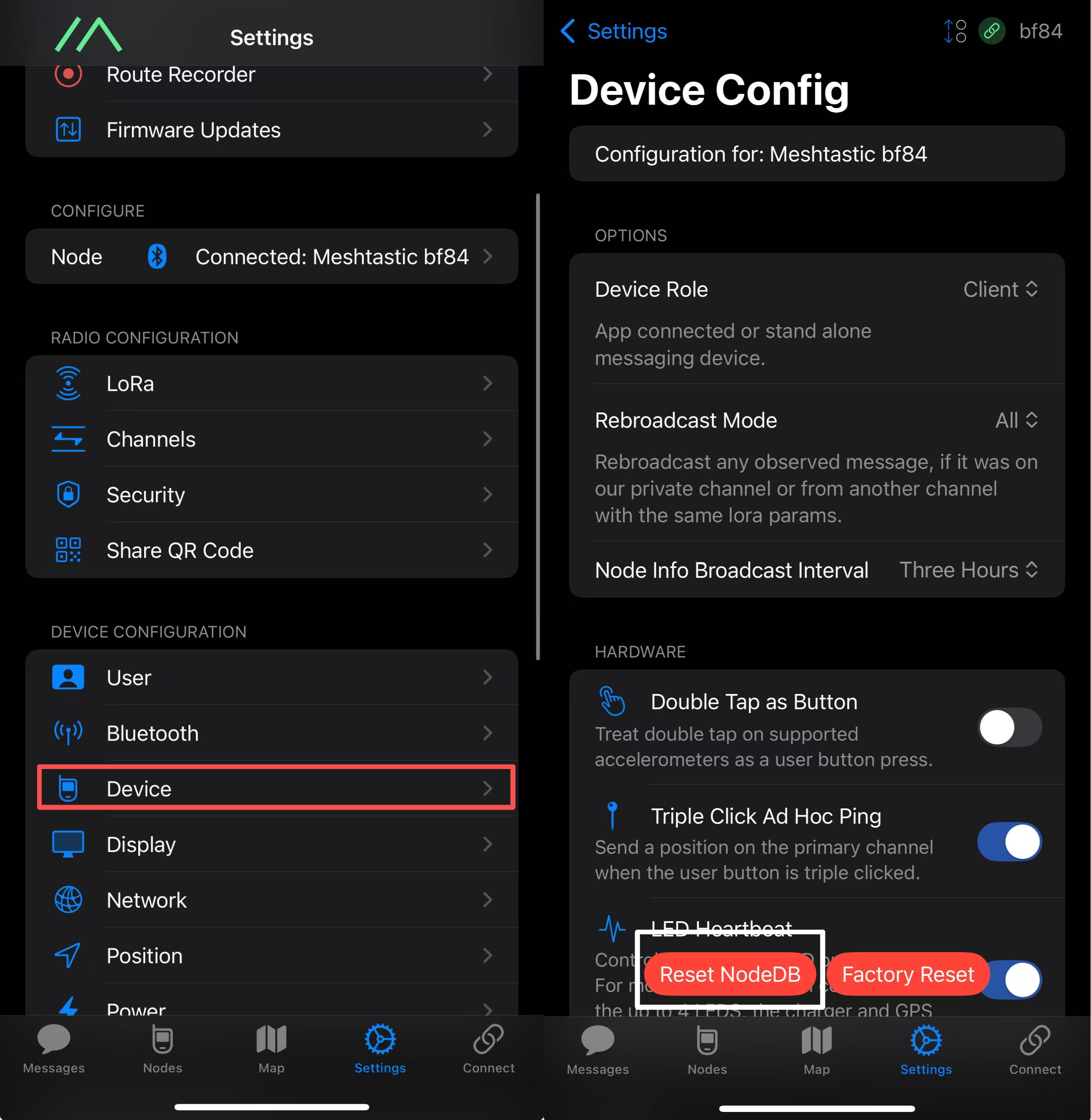
NodeDB is the local database that stores information about nodes discovered in the current Mesh network. If you encounter a situation where you can't communicate with a certain node, it might be because your nodedB has stored outdated information for that node. You will need to update it.
Open the app and connect to the target device. Go to Settings->Device->Device Config->Reset NodeDB.
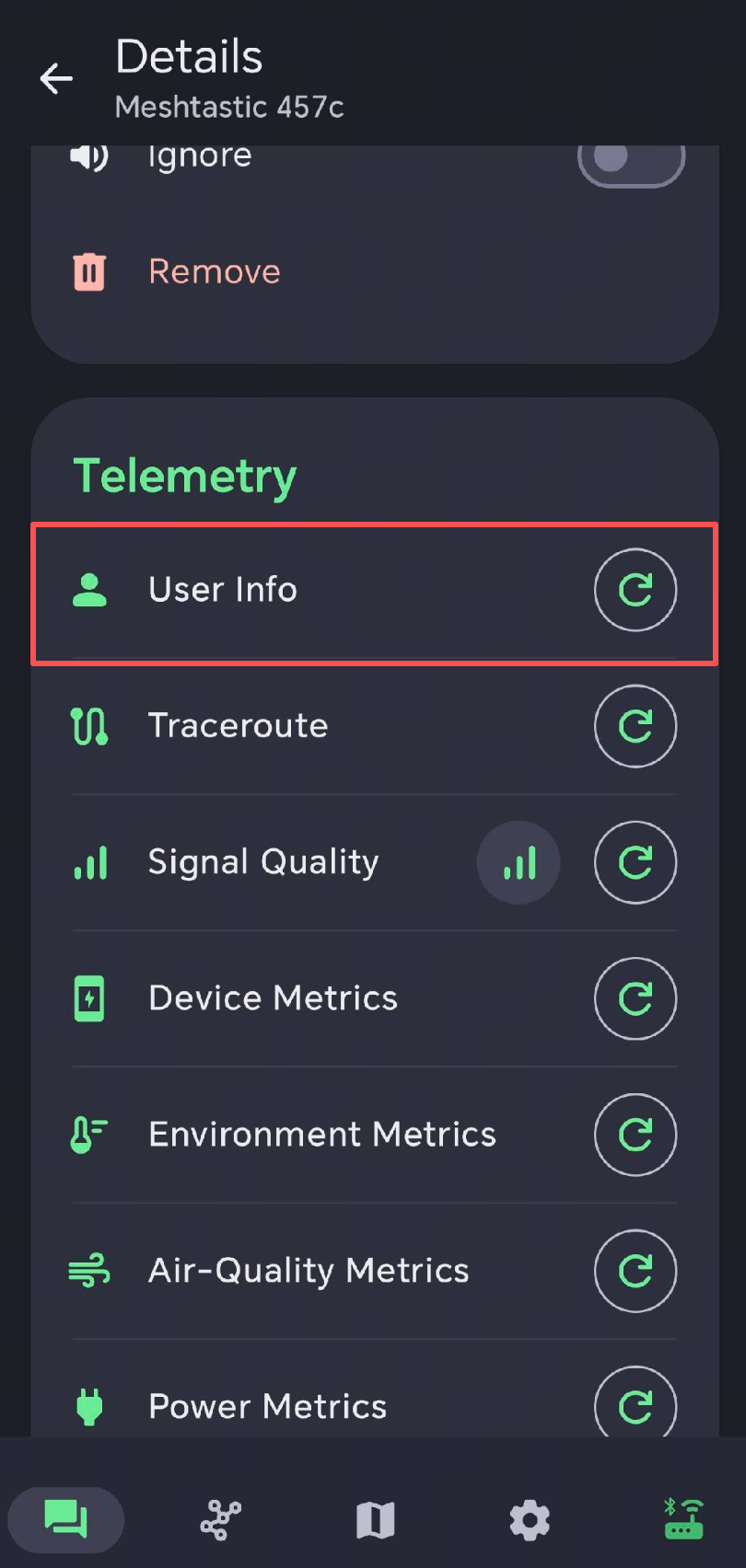
Exchange User Info
Each node will periodically send its own node information, enabling other nodes in the mesh to "see" and "recognize" it. Two nodes need to exchange their node information with each other in order to be able to communicate with each other. If you are unable to send or receive private messages with another node on the list, you can manually prompt them to exchange information in the app.
Regenerate Private Key
Each node owns a public/private key pair. To exchange an encrypted private message, the sender encrypts it with the recipient's public key, and only that recipient's private key can decrypt it. Two nodes can therefore communicate privately once they know each other's public key. If one node keeps failing in private-message transmission, try regenerating its private key. After regeneration, delete that node from the other devices' node lists so they can reconnect and obtain its new public key.
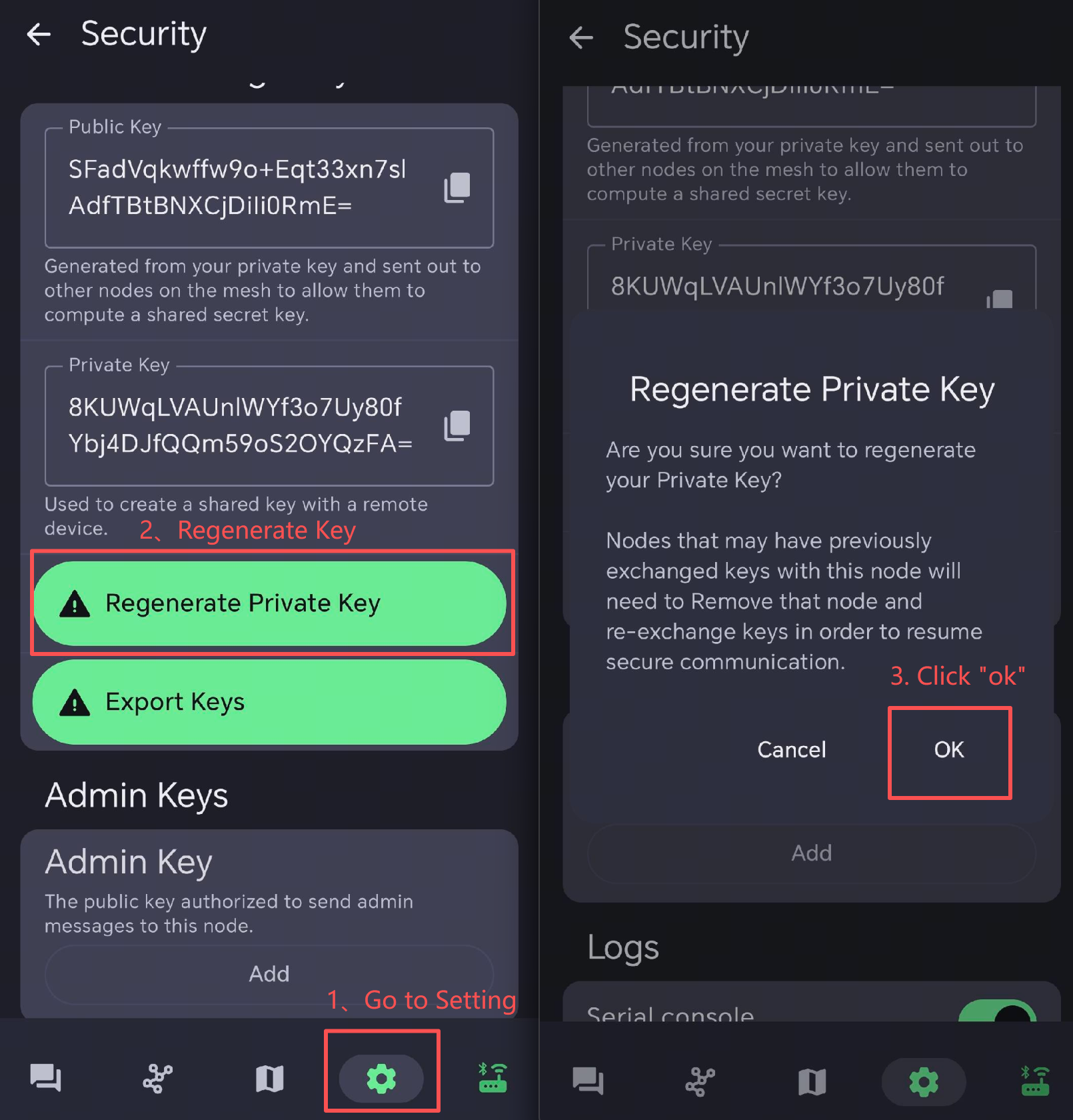
Reboot the faulty device to make the configuration function.
After the key regeneration, other device needs to reconnect with the node. So it is better to delete the node in other device's node list.
Signal Quality
-
SNR reflects the quality of the communication link. Normal device usually operates above -7 dB. Device with a SNR lower than -10 dB indicates poor performance.
-
RSSI is determined jointly by the device and its surrounding environment. Normal device usually operates above -110 dBm. Device with an RSSI lower than -115 dBm is considered to have poor performance.
To achieve the best signal effect, please use the device in an open, unobstructed area with minimal interference for use.
Compatible Antenna
If you need a antenna replacement for L1 Pro, click here to get one.
Resources
- Bootloader (Serial DFU package)
- (V1) 3D printing reference file
- (V2 New Four-way Joystick) 3D printing reference file
- L1 Enclosure Design Challenge
- Outline File
- TELEC Certification
- FCC Certification
- CE Certification
- Power Consumption Test and Battery Life Calculation
Tech Support & Product Discussion