Getting Started with XIAO 0.96'' IPS Display (nRF52840)
| XIAO 0.96'' IPS Display (nRF52840) |
|---|
 |
Introduction
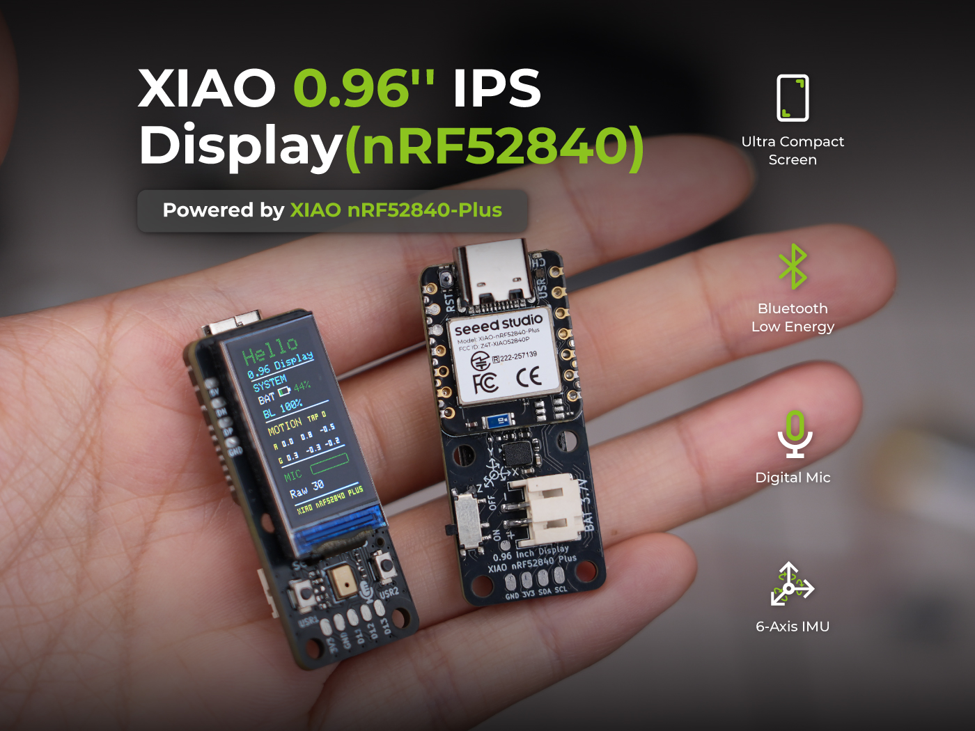
The 0.96'' IPS Display is an expansion board designed for the XIAO series, powered by the XIAO nRF52840 Plus. It features a compact 80×160 IPS color LCD, onboard PDM microphone, 6-axis IMU (LSM6DS3), two user buttons, and battery power management with percentage display — all packed into a form factor even smaller than the 1.14'' IPS Display.
This combination makes it an ideal platform for ultra-compact wearables, keychain gadgets, portable sensor nodes, and IoT prototyping where every millimetre of space counts.
| Specification | Detail |
|---|---|
| Product Positioning | Ultra-Compact |
| Core Controller | Seeed Studio XIAO nRF52840 Plus |
| Processor | Nordic nRF52840, ARM® Cortex®-M4 32-bit processor with FPU, 64 MHz |
| Memory | 256 KB RAM + 1 MB internal Flash + 2 MB onboard Flash |
| Wireless Connectivity | BLE 5.4 |
| Display Type | 0.96" IPS TFT LCD |
| Resolution | 80 × 160 |
| Display Driver | ST7789 |
| Display Interface | SPI |
| Touch Input | No |
| 6-Axis IMU | Yes |
| PDM Digital Microphone | Yes |
| MicroSD Card Slot | No |
| Grove I2C Connector | No |
| User Buttons | 2 |
| Battery Connector | 2-pin JST 2.0 Connector for 3.7 V LiPo |
| Battery Monitoring | Battery status detection supported; battery voltage can also be monitored for battery-level estimation. |
| Expansion Interfaces | 1x I2C Interface, 1x I2S Interface, 1x SWD Interface, 2x User Button Interface |
| Board Size | 18.8 × 43.6 × 10.6 mm |
| Best For | Smart badges, tiny wearables, BLE status displays |
This display board is designed for the XIAO nRF52840 Plus. If you are using the XIAO ESP32-S3 Plus version, please refer to the XIAO 0.96'' IPS Display (ESP32-S3) guide instead.
Hardware Overview
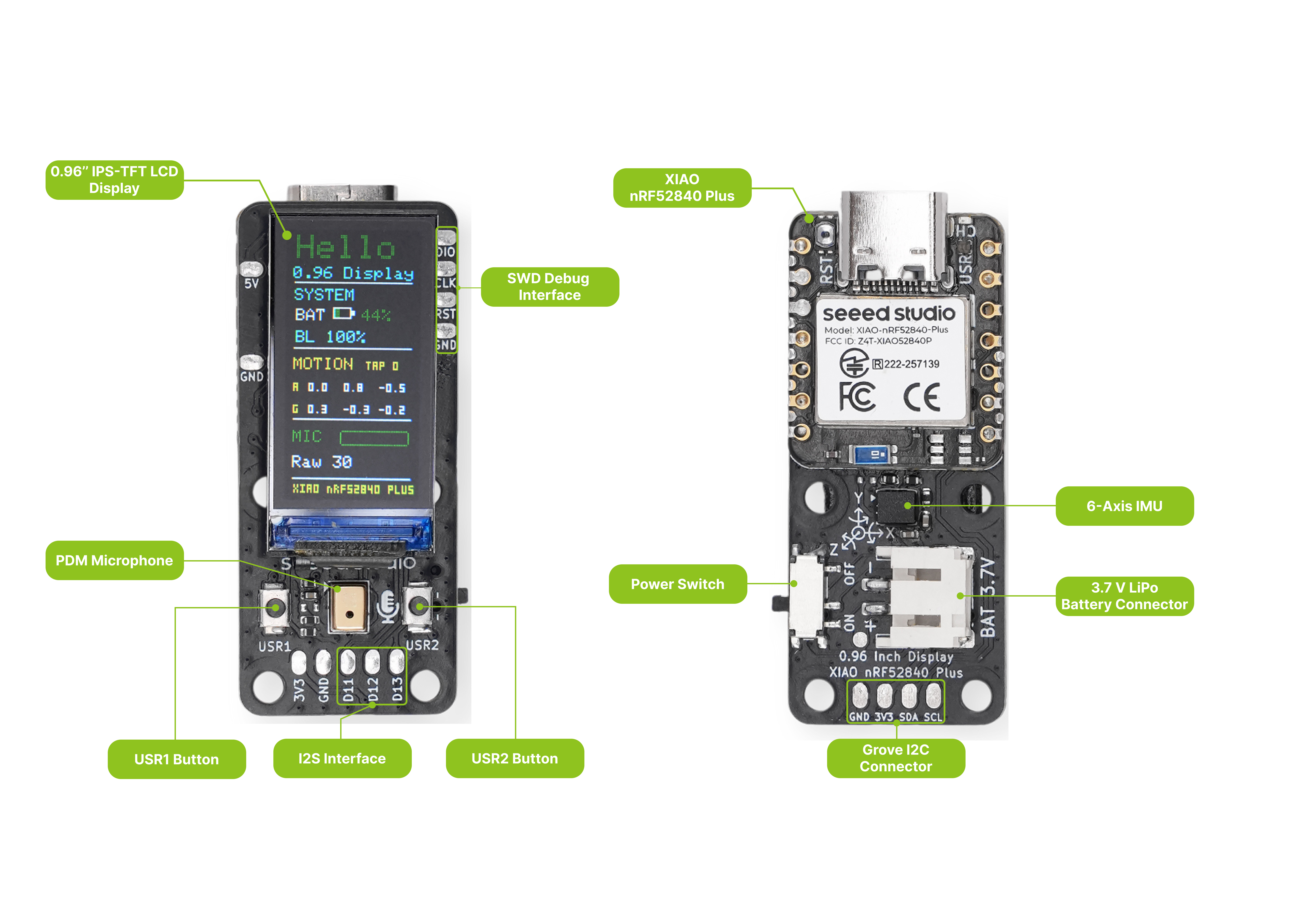
Before we start, refer to the following image to understand the physical layout of the 0.96'' IPS Display.
Pin Map
The 0.96'' IPS Display breaks out all XIAO nRF52840 Plus pins. The table below lists every pin, its net name on the display board, its function, and how it is connected to onboard peripherals.
| XIAO Pin | Net Name | Function Description | Hardware Connection Notes |
|---|---|---|---|
| D0 | PDM_CLK | PDM digital microphone clock | Internally connected to PDM Mic |
| D1 | PDM_DATA | PDM digital microphone data | Internally connected to PDM Mic |
| D2 | LCD_CS | Screen chip select signal | Internally connected to LCD driver IC |
| D3 | LCD_DC | Screen data/command switch | Internally connected to LCD driver IC |
| D4 | SDA | I2C data bus | Bus sharing: internally connected to IMU; externally exposed to the back-side 4-pin test pad |
| D5 | SCL | I2C clock bus | Bus sharing: internally connected to IMU; externally exposed to the back-side 4-pin test pad |
| D6 | BTN_USR1 | User button 1 (KEY1) | Internally connected to microswitch 1; cycles backlight brightness |
| D7 | BTN_USR2 | User button 2 (KEY2) | Internally connected to microswitch 2; toggles backlight ON/OFF |
| D8 | LCD_SCK | Hardware SPI clock | Internally connected to LCD driver IC |
| D9 | NC | Floating (reserved) | No physical connection |
| D10 | LCD_MOSI | Hardware SPI data output | Internally connected to LCD driver IC |
| D11 | I2S_SD | Audio data output | Externally exposed to the bottom audio expansion pad |
| D12 | I2S_SCK | Audio bit clock | Externally exposed to the bottom audio expansion pad |
| D13 | I2S_WS | Audio word select | Externally exposed to the bottom audio expansion pad |
| D14 | IMU_INT | IMU motion hardware interrupt | Internally connected to 6-axis IMU (supports motion wake-up) |
| D15 | NC | Floating (reserved) | No physical connection |
| D16 | NC | Floating (reserved) | No physical connection — battery voltage is measured through the module's internal PIN_VBAT, not through D16 |
| D17 | LCD_RST | Screen soft reset | Internally connected to LCD driver IC |
| D18 | LCD_BL | Screen backlight control | Internally connected to backlight driver circuit |
| D19 | NC | Floating (reserved) | No physical connection |
Getting Started
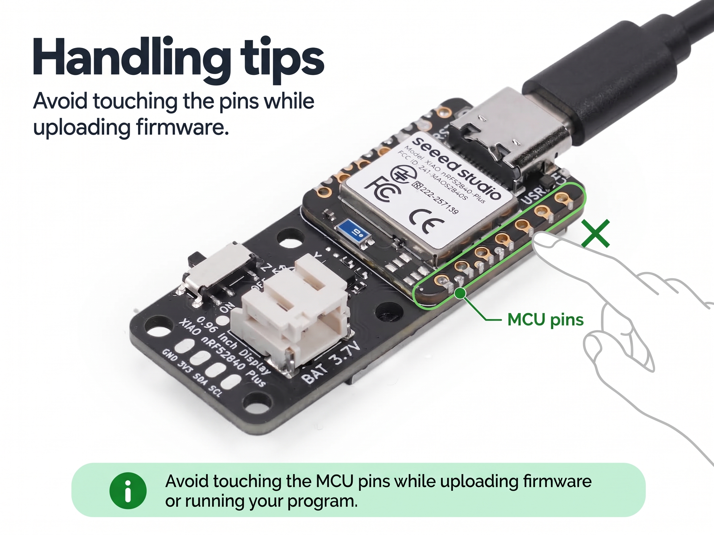
This guide uploads a minimal "Hello, XIAO" sketch to the display board: the screen turns on its backlight, fills black, and prints "Hello," and "XIAO" as two centered lines of large green text. It is the fastest way to confirm the screen and your development environment are working before diving into the individual peripheral demos.
Software Preparation
You will need the following tools and libraries:
- Arduino IDE (version 1.8 or later)
- Seeed nRF52 Boards (1.1.13) — add the following URL to File > Preferences > Additional Boards Manager URLs:
https://files.seeedstudio.com/arduino/package_seeeduino_boards_index.json
Then go to Tools > Board > Boards Manager, search for Seeed nRF52 and install version 1.1.13.
- Seeed_GFX2 (Manual Installation) — this library is not available in the Library Manager and must be installed manually:
Step 1. Click the button above to download Seeed_GFX2 v1.0.0 as a ZIP file (pinned to a release tag so the tutorial stays reproducible). Alternatively, clone the repository from Seeed-Studio/Seeed_GFX2.
Step 2. In the Arduino IDE, go to Sketch > Include Library > Add .ZIP Library... and select the downloaded ZIP. The IDE reads library.properties and installs it into the correct Seeed_GFX2 folder automatically — you do not need to rename the extracted folder. (To install manually instead, unzip the archive and rename the extracted folder to Seeed_GFX2 before placing it in Documents/Arduino/libraries/.)
Step 3. Restart the Arduino IDE so the new library is detected.
- Seeed_GFX2 is Seeed Studio's graphics library built on a layered
Board+Panel Configarchitecture. Each demo initializes the display with a singledisplay.begin<Board_..., Config_...>()call — the Board template owns the pin map (CS/DC/SCK/MOSI/RST/BL), and the Panel Config bakes in the 80×160 resolution, color order (BGR), and orientation. Nodriver.hor manual pin setup is needed. - On this board the sketch uses
Board_XIAO_0inch96_LCD<38, 37>(RST=38, BL=37) withConfig_Seeed_0inch96_LCD_ST7789. - The Adafruit TinyUSB library used by the sketch is bundled with the Seeed nRF52 Boards package, so it needs no separate installation.
Download the Code
The example sketch is available on GitHub:
Navigate to code_GFX2/getting_started_code/xiao_nrf52840_096_hello/ and open xiao_nrf52840_096_hello.ino in the Arduino IDE. Download the complete folder rather than copying the .ino source from the GitHub web view.
Upload the Sketch
Step 1. Connect the XIAO nRF52840 Plus to your computer via the USB-C port.
Step 2. In Arduino IDE, select the board: Tools > Board > Seeed nRF52 Boards > Seeed XIAO nRF52840 Plus.
Step 3. Select the correct Port under Tools > Port.
Step 4. Click the Upload button (→). The sketch will compile and upload to the board.
If you encounter upload issues, double-click the reset button to enter bootloader mode. The USR LED will breathe in red and a NRF52BOOT drive will appear on your computer, indicating the board is in bootloader mode.
Expected Output
After uploading, the screen lights up with a black background and shows two centered lines of large green text — "Hello," on the first line and "XIAO" on the second. The greeting stays on screen without redrawing.
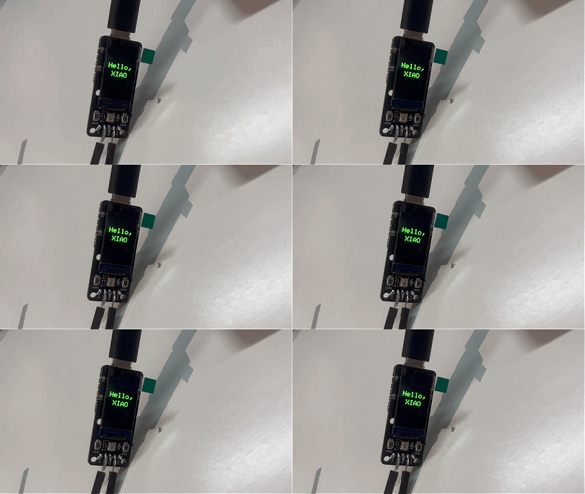
If the display fails to initialize, the sketch prints the library error message to the serial monitor at 115200 baud. Open Tools > Serial Monitor and set the baud rate to 115200 to read it.
What's Next
The display board packs several onboard peripherals. The Function page provides a standalone demo for each one:
| Peripheral | Demo |
|---|---|
| Screen | GraphicTest — ten graphics primitives with timing benchmarks |
| IMU | Electronic Quicksand + Raise to Wake — 6-axis motion effects and wake-on-motion |
| Microphone & Speaker | Flash Recorder — record and play back audio |
| Buttons | User Buttons — read presses and debounce with interrupts |
| Battery | Battery Status — measure voltage and convert to a percentage |
FAQ
What if the upload fails or the board is not detected?
Double-click the reset button on the XIAO nRF52840 Plus. The USR LED will breathe in red and a drive named NRF52BOOT will appear on your computer. Drag the compiled .uf2 file onto the NRF52BOOT drive. The board will program itself and reset automatically.
Resources
- 🗃️[PCB Design Files] XIAO 0.96'' IPS Display (nRF52840) KiCad Project
- 📄[Schematic] XIAO 0.96'' IPS Display (nRF52840) Schematic
- 📦[3D Model] XIAO 0.96'' IPS Display (STEP)
- 🖨️[3D Printed Enclosure] XIAO 0.96'' IPS Display Enclosure (by gokul)
- 📄[Datasheet] 0.96 Inch Display Datasheet
- 💾[Factory Firmware] XIAO 0.96'' IPS Display (nRF52840) Factory Firmware
Tech Support & Product Discussion
Thank you for choosing our products! We are here to provide you with different support to ensure that your experience with our products is as smooth as possible. We offer several communication channels to cater to different preferences and needs.