Getting Started with COB LED Driver Board for Seeed Studio XIAO

This is a 7-channel COB LED driver dock designed for Seeed Studio XIAO. This expansion board breaks GPIO power limits, offering 7 output channels, specifically tailored for ultra-narrow 1mm 3V COB LED strips. With integrated PMIC battery management, it is the ideal plug-and-play solution for building compact, high-brightness wireless lighting setups.
Safety Notes
Operation Prohibitions & Safety Rules
- Do not connect any peripherals during charging. Disconnect the light bar first before plugging in the USB-C cable.
- When debugging the USB-C port, the battery holder must be empty (no battery installed).
- For full load currents >1A, ensure heat dissipation holes are drilled in the housing; otherwise, the PMIC will overheat and shut down.
- Never touch the PMIC area on the back of the board with bare hands: electrostatic discharge (ESD) can damage the chip, and the surface may reach scalding temperatures under full load. Core Safety Reminders
- Adhere to these four rules for safe operation:
- Single power supply when peripherals are connected
- Power off before wiring/disconnecting
- Provide adequate heat dissipation holes
- Do not touch the backside of the board

Introduction
Feature
-
Adapted for 1mm 3V COB LED Strips
The onboard hardware current limiting is specifically tuned to match the electrical characteristics of 3V 1mm flexible COB strips.The tiered 300mA and 100mA current limits effectively drive strips of various lengths,providing Makers with a safe,stable and plug-and-play experience.
-
Strategic 7-Channel Hybrid Output
Efficiently manages your entire lighting setup with a single board. It features 3 High-Power Channels (300mA) for bright main lighting and 4 Dimmable Channels (80mA) for delicate breathing or fading effects. One board handles it all—keeping your main lights bright and your effects dynamic.
-
Battery Management for Wireless Projects
Integrated power circuit supports 3.7V Li-Po batteries or high-power 5V USB adapters.Perfect for building both wireless installations and high-brightness desktop ambient lighting.
-
Easy Sensor Expansion
Includes a standard Grove I2C connector for hassle-free connection to sensors,allowing your lighting projects to react intelligently to the environment.
Specification
| LED Power Support | DC 3V |
|---|---|
| Power Input | 5V USB (via XIAO) |
| 3× High-Power Ports (Screw Terminals) | 3 Channels Output |
| 4× FX/PWM Ports (Bottom Pads) | 4 Channels Output |
| Onboard | Grove I²C Connector ×1 |
| Dimensions | 30mm*41mm*16mm (With a Seeed Studio XIAO) |
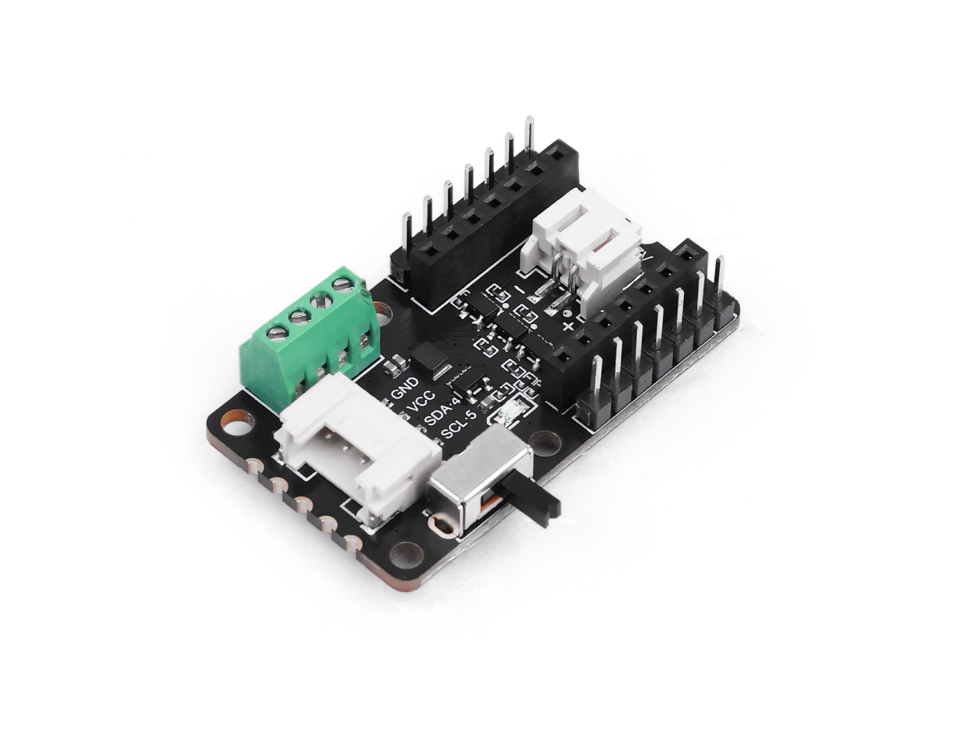
Hardware Overview

- (1) D1-High-Power Port: A high-power port that supports a maximum current of 300mA, only allows ON/OFF switch control (PWM dimming is not supported), and is used to connect high-power loads.
- (2) D0-High-Power Port: A high-power port that supports a maximum current of 300mA, only allows ON/OFF switch control (PWM dimming is not supported), and is used to connect high-power loads.
- (3) VCC-Always-On Port: An always-powered VCC port that supports a maximum current of 300mA, is not controlled by the power switch, always outputs the supply voltage, and can power devices that require continuous power.
- (4) GND: The common ground port of the circuit, used to connect the ground wires of all modules.
- (5) I²C Grove Port: A Grove-standard I²C interface (including VCC, GND, SDA, SCL pins), used to connect Grove modules that support the I²C protocol (such as sensors, displays).
- (6) Power Switch: A power control switch; when toggled to "ON", it supplies power to high/low-power ports; when toggled to "OFF", it cuts off power (the VCC always-on port is not controlled by this switch).
- (7) Power LED: A power status indicator light that turns on when the power switch is toggled to "ON", indicating the module is powered.
- (8) Battery Connector: A battery interface that supports connection of 3.7V lithium batteries to power the module.
- (9) D2-Low-Power Port: A low-power port that supports a maximum current of 80mA, supports PWM dimming, and uses active LOW logic (the load operates when the level is low).
- (10) GND: A ground port in the low-power area, used to connect the ground wires of low-power loads.
- (11) D3-Low-Power Port: A low-power port that supports a maximum current of 80mA, supports PWM dimming, and uses active LOW logic (the load operates when the level is low).
- (12) D9-Low-Power Port: A low-power port that supports a maximum current of 80mA, supports PWM dimming, and uses active LOW logic (the load operates when the level is low).
- (13) D8-Low-Power Port: A low-power port that supports a maximum current of 80mA, supports PWM dimming, and uses active LOW logic (the load operates when the level is low).
Supported COB LEDs Guide
Supported LEDs Guide
| Product | Name | Length | Operating Current | Luminous Flux |
|---|---|---|---|---|
-38mm.jpg) | Double Ended COB LED Strip - White(6500K) | 38mm | 100mA (Recommended) | >20 lm (@ 100mA) |
 300mm.jpg) | Double Ended COB LED Strip - White(6500K) | 130mm | 300mA (Recommended) | 21-25 lm (@ 300mA) |
| Double Ended COB LED Strip - White(6500K) | 300mm | 300mA (Recommended) | >50 lm (@ 300mA) |
-110mm.jpg) | Single Ended COB LED Strip - White(6500K) | 110mm | 100mA (Recommended) | >23 lm (@ 200mA) |
-300mm.jpg) | Single Ended COB LED Strip - White(6500K) | 300mm | 100mA (Recommended) | >22 lm (@ 100mA) |
Getting Started
To unlock the full potential of the COB LED Driver Board and enjoy the best possible experience, we strongly recommend pairing it with a Seeed Studio XIAO board and our matching COB LED strips.
For safety:
- When charging the Li-ion battery, disconnect the LED strip and any other peripherals.
- When connecting USB-C 5 V for programming or debugging, disconnect the battery.
Using either the battery alone or the 5 V external supply alone is safe.It is not recommended to connect peripheral devices while charging.
Play with Arduino
You need to configure the Arduino environment for the XIAO and add the on-board package.
If this is your first time using Arduino, we highly recommend you to refer to Getting Started with Arduino.
Software Preparation
Step 1. Launch the Arduino application.
Step 2. Select your development board model and add it to the Arduino IDE.
-
If you want to use Seeed Studio XIAO RP2040 for the later routines, please refer to this tutorial to finish adding.
-
If you want to use Seeed Studio XIAO RP2350 for the later routines, please refer to this tutorial to finish adding.
-
If you want to use Seeed Studio XIAO nRF52840 for the later routines, please refer to this tutorial to finish adding.
-
If you want to use Seeed Studio XIAO ESP32-C3 for the later routines, please refer to this tutorial to finish adding.
-
If you want to use Seeed Studio XIAO ESP32-C6 for the later routines, please refer to this tutorial to finish adding.
-
If you want to use Seeed Studio XIAO ESP32-S3 for the later routines, please refer to this tutorial to finish adding.
-
If you want to use Seeed Studio XIAO RA4M1 for the later routines, please refer to this tutorial to finish adding.
-
If you want to use Seeed Studio XIAO MG24 for the later routines, please refer to this tutorial to finish adding.
The XIAO SAMD21 and XIAO nRF54L15 only work when powered via USB-C and cannot be used with a battery alone. Additionally, the nRF54L15 does not operate in the Arduino environment.
Low-Power Port Driver Example
A low-power port that supports a maximum current of 80mA, supports PWM dimming, and uses active LOW logic (the load operates when the level is low).
Step 1. Hardware preparation
| Seeed Studio XIAO ESP32-C3 | COB LED Driver Board | Single Ended COB LED Strip |
|---|---|---|
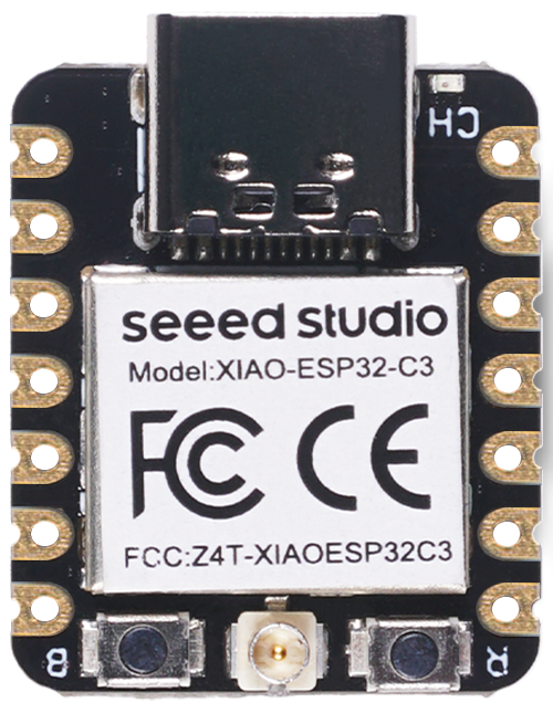 |  | |
When connecting the XIAO to the driver board, be sure to unplug the USB cable.
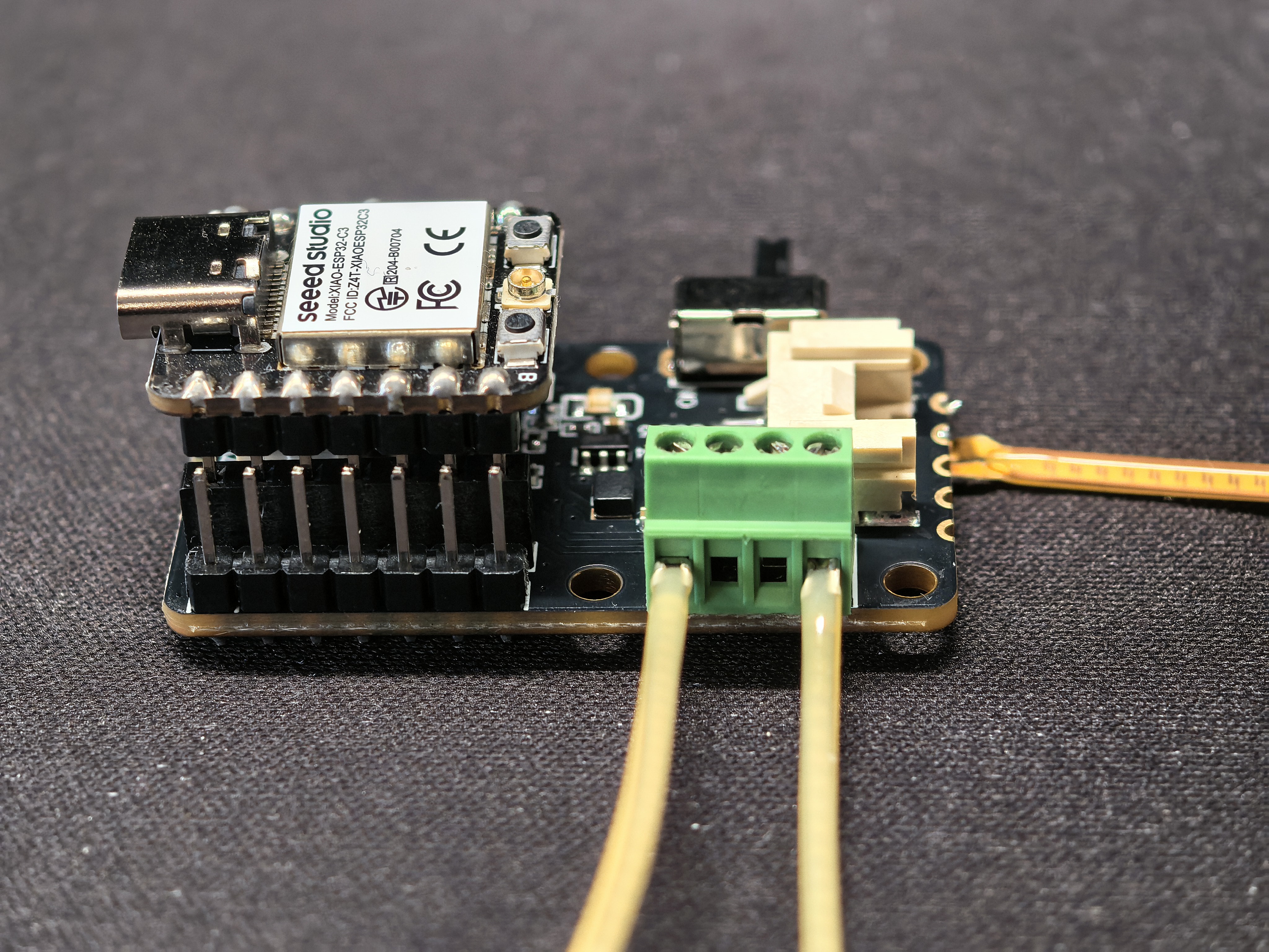
Step 2. Connect Seeed Studio XIAO ESP32-C3,COB LED Driver Board for XIAO and Single Ended COB LED Strip as show below:
-300mm.jpg)

Step 3. Connect the XIAO to the USB flashing program. Copy and download the related example sketch.
#define LED_BUILTIN     D2
// the setup function runs once when you press reset or power the board
void setup() {
  // initialize digital pin LED_BUILTIN as an output.
  pinMode(LED_BUILTIN, OUTPUT);
}

// the loop function runs over and over again forever
void loop() {
  digitalWrite(LED_BUILTIN, LOW);   // turn the LED on by making the voltage LOW
 // digitalWrite(LED_BUILTIN, HIGH);  // turn the LED off (HIGH is the voltage level)
}
“Low-Power Port” in the comment means active-low: pull the pin LOW to turn the strip ON, release (HIGH) to turn it OFF.
The code simply controls the GPIO pins HIGH or LOW. Since the driver board is already configured, you do not need to download any extra libraries. Follow the image link,upload the program and power COB LED Driver Board, if all goes well, you can see like this:

High-Power Port Driver Example
A high-power port that supports a maximum current of 300mA, only allows ON/OFF switch control (PWM dimming is not supported), and is used to connect high-power loads.
Step 1. Hardware preparation
| Seeed Studio XIAO ESP32-C3 | COB LED Driver Board | Double Ended COB LED Strip |
|---|---|---|
| | |
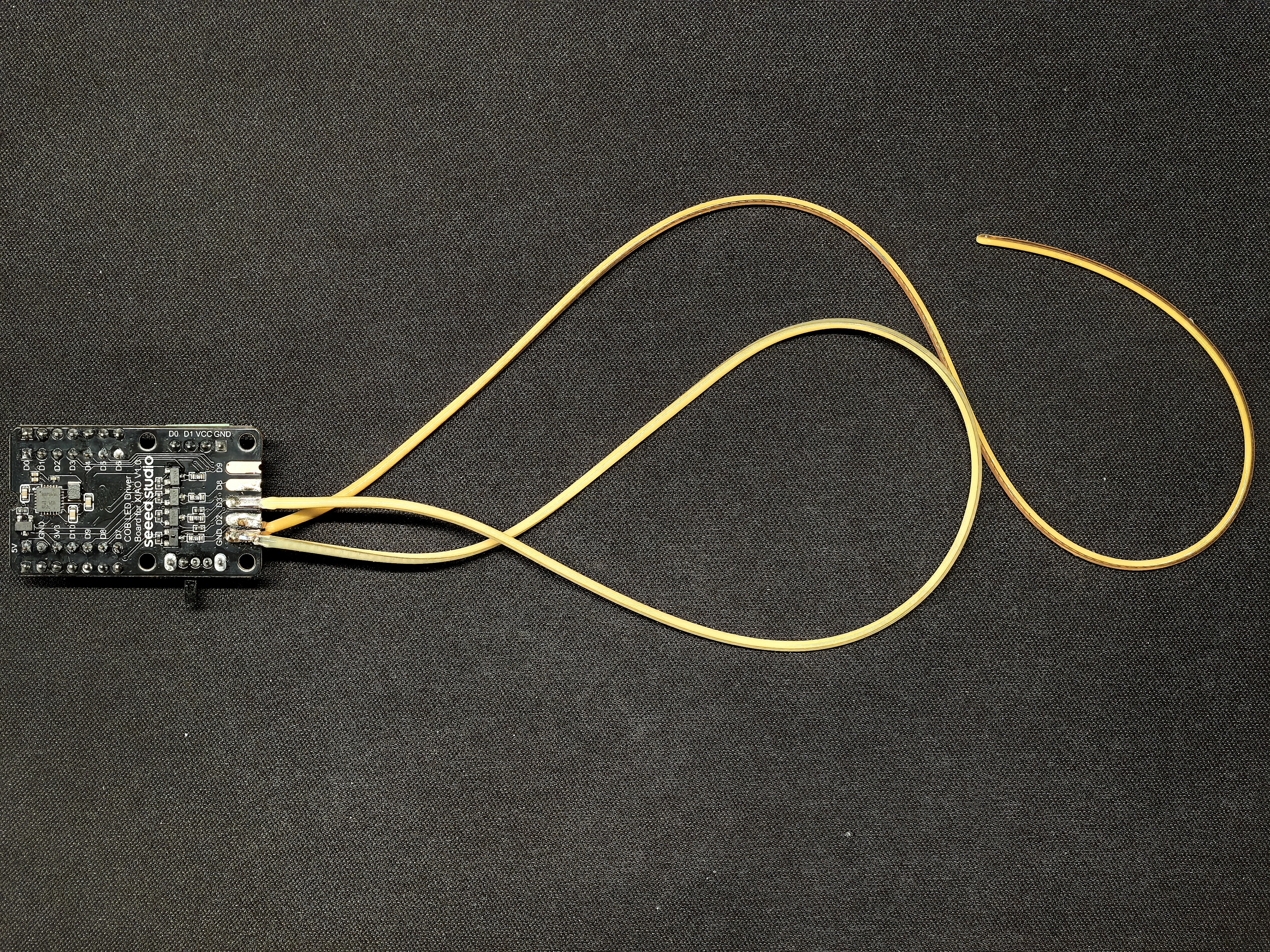
Step 2. Connect Seeed Studio XIAO ESP32-C3,COB LED Driver Board for XIAO and Double Ended COB LED Strip as show below:
-130mm.jpg)
Step 3. Connect the XIAO to the USB flashing program. Copy and download the related example sketch.
#define LED_BUILTIN       D0

// the setup function runs once when you press reset or power the board
void setup() {
  // initialize digital pin LED_BUILTIN as an output.
  pinMode(LED_BUILTIN, OUTPUT);
}

// the loop function runs over and over again forever
void loop() {
  digitalWrite(LED_BUILTIN, HIGH);  // turn the LED on (HIGH is the voltage level)
 // digitalWrite(LED_BUILTIN, LOW);   // turn the LED off by making the voltage LOW
}
The code simply controls the GPIO pins HIGH or LOW. Since the driver board is already configured, you do not need to download any extra libraries. Follow the image link,upload the program and power COB LED Driver Board, if all goes well, you can see like this:
Low-Power Port Driver PWM Example
A low-power port that supports a maximum current of 80mA, supports PWM dimming, and uses active LOW logic (the load operates when the level is low). Step 1. Hardware preparation
| Seeed Studio XIAO ESP32-C3 | COB LED Driver Board | Single Ended COB LED Strip | Double Ended COB LED Strip |
|---|---|---|---|
| | | |
Step 2. Connect Seeed Studio XIAO ESP32-C3,COB LED Driver Board for XIAO,Single Ended COB LED Strip and Double Ended COB LED Strip as show below:
Step 3. Connect the XIAO to the USB flashing program. Copy and download the related example sketch.
#include <Arduino.h>

// ================= Define Pins =================
const int PIN_STRIP_1 = D2;
const int PIN_STRIP_2 = D3;

// ================= Parameter Configuration =================
// Breathing speed: larger number = slower, smaller number = faster
const int BREATH_SPEED = 2000;

// Breathing phase offset: determines if the two light strips "light up together" or "alternate lighting"
// float PHASE_OFFSET = 0;    // Set to 0 -> fully synchronized
float PHASE_OFFSET = PI;   // Set to PI (3.14) -> fully alternating (complementary)
// float PHASE_OFFSET = PI/2; // Set to PI/2 -> slightly staggered rhythm

// ================= Helper Function: Handle Active LOW Lighting Logic =================
// This step is crucial, do not modify
// Input: brightness (0=off, 255=maximum brightness)
void setLedBrightness(int pin, int brightness) {
  // 1. Safety limit range
  brightness = constrain(brightness, 0, 255);

  // 2. Logic inversion (Active LOW)
  // Brightness 255 -> Output 0 (GND) -> Light at maximum brightness
  // Brightness 0   -> Output 255 (VCC) -> Light off
  int pwmValue = 255 - brightness;

  analogWrite(pin, pwmValue);
}

// ================= Math Function for Calculating Breathing Brightness =================
// Using the algorithm (e^sin(x) - 1/e), which mimics human breathing curve better than ordinary triangular wave
int calculateBreathBrightness(unsigned long time, float phaseOffset) {
  // Calculate angle: time / speed factor
  float angle = (time / (float)BREATH_SPEED) * PI;

  // Add phase offset
  angle += phaseOffset;

  // Core formula
  float val = (exp(sin(angle)) - 0.36787944) * 108.0;

  return (int)val;
}

void setup() {
  pinMode(PIN_STRIP_1, OUTPUT);
  pinMode(PIN_STRIP_2, OUTPUT);

  // Initialization: turn off all lights first
  setLedBrightness(PIN_STRIP_1, 0);
  setLedBrightness(PIN_STRIP_2, 0);
}

void loop() {
  unsigned long currentMillis = millis();

  // 1. Calculate brightness for D2 (no offset)
  int bright1 = calculateBreathBrightness(currentMillis, 0);
  setLedBrightness(PIN_STRIP_1, bright1);

  // 2. Calculate brightness for D3 (with offset)
  int bright2 = calculateBreathBrightness(currentMillis, PHASE_OFFSET);
  setLedBrightness(PIN_STRIP_2, bright2);

  // The delay here doesn't need to be too long, just give the CPU a short break
  delay(5);
}
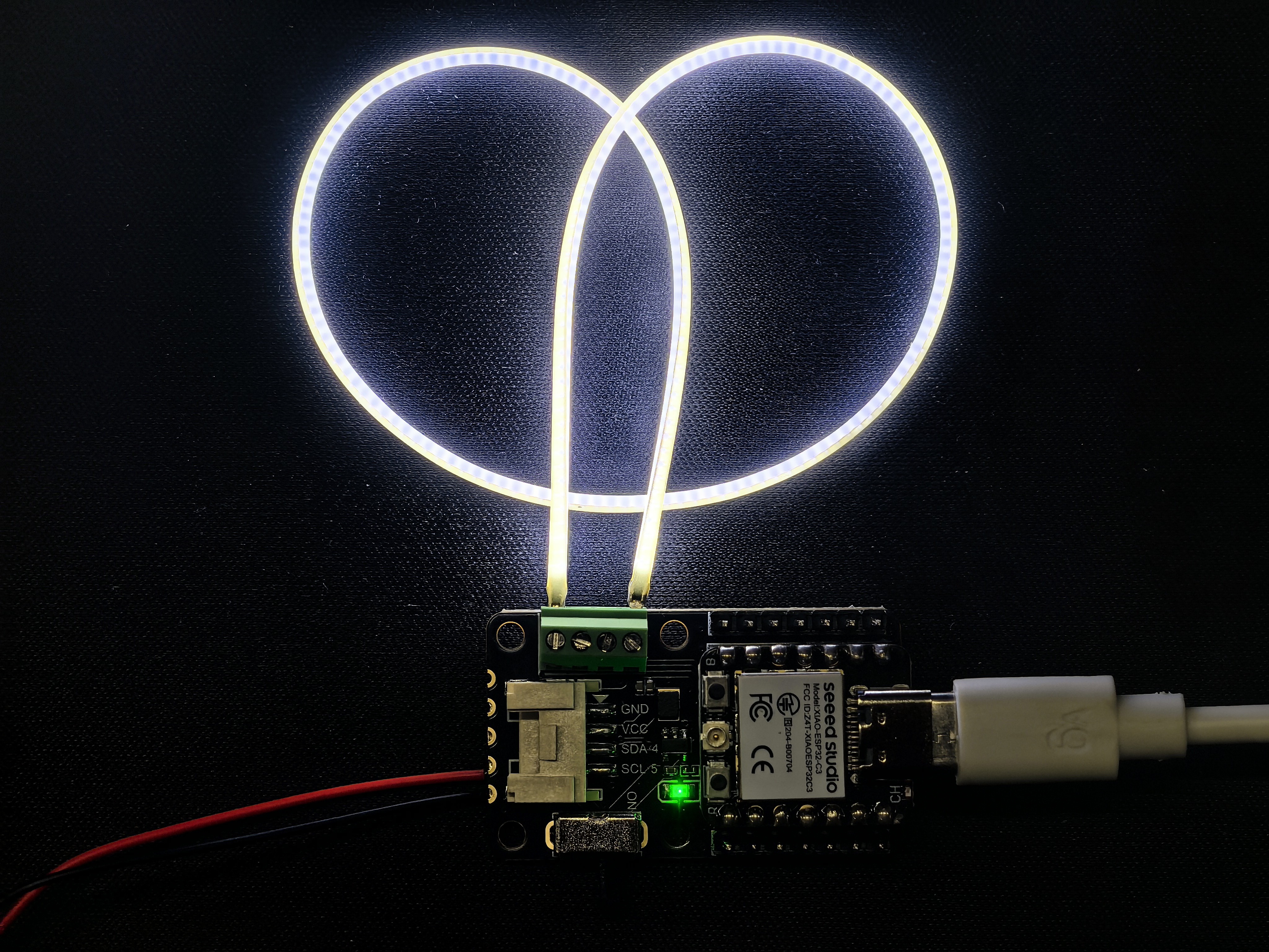
This is a battery-powered project.This is the code for the breathing light style, if you like, you can use this style anywhere you want to shine Upload the program and power COB LED Driver Board, if all goes well, you can see like this:
LED strips with a rated current limit of 300mA or 100mA can both be safely connected to a port with a maximum output of 80mA (the port's output current is ≤ the LED strip's current limit, ensuring safety redundancy). However, an LED strip with a rated current limit of 100mA cannot be connected to a port with a maximum output of 300mA—since the port’s maximum output current far exceeds the LED strip’s current limit, this may damage the strip due to overcurrent.
Hot-plugging is strictly prohibited! Always assemble the XIAO and the driver board first, then plug in the USB cable. Never try to mate the XIAO while it is still connected to the USB cable。May cause the PMIC to break down.
Play with Home Assistant via ESPHome
Hardware Preparation
| Home Assistant Devices |
|---|
 |
Software Preparation
ESPHome is a tool which aims to make managing your ESP boards as simple as possible. It reads in a YAML configuration file and creates custom firmware which it installs on your ESP device. Devices or sensors added in ESPHome’s configuration will automatically show up in Home Assistant’s UI. ESPHome can help you connect and send the data to Home Assistant devices.
If this is your first time using Home Assistant and ESPHome, you can follow here for a step-by-step guide on installing Home Assistant.
ESPHome is available as a Home Assistant Add-On and can simply be installed via the add-on store.
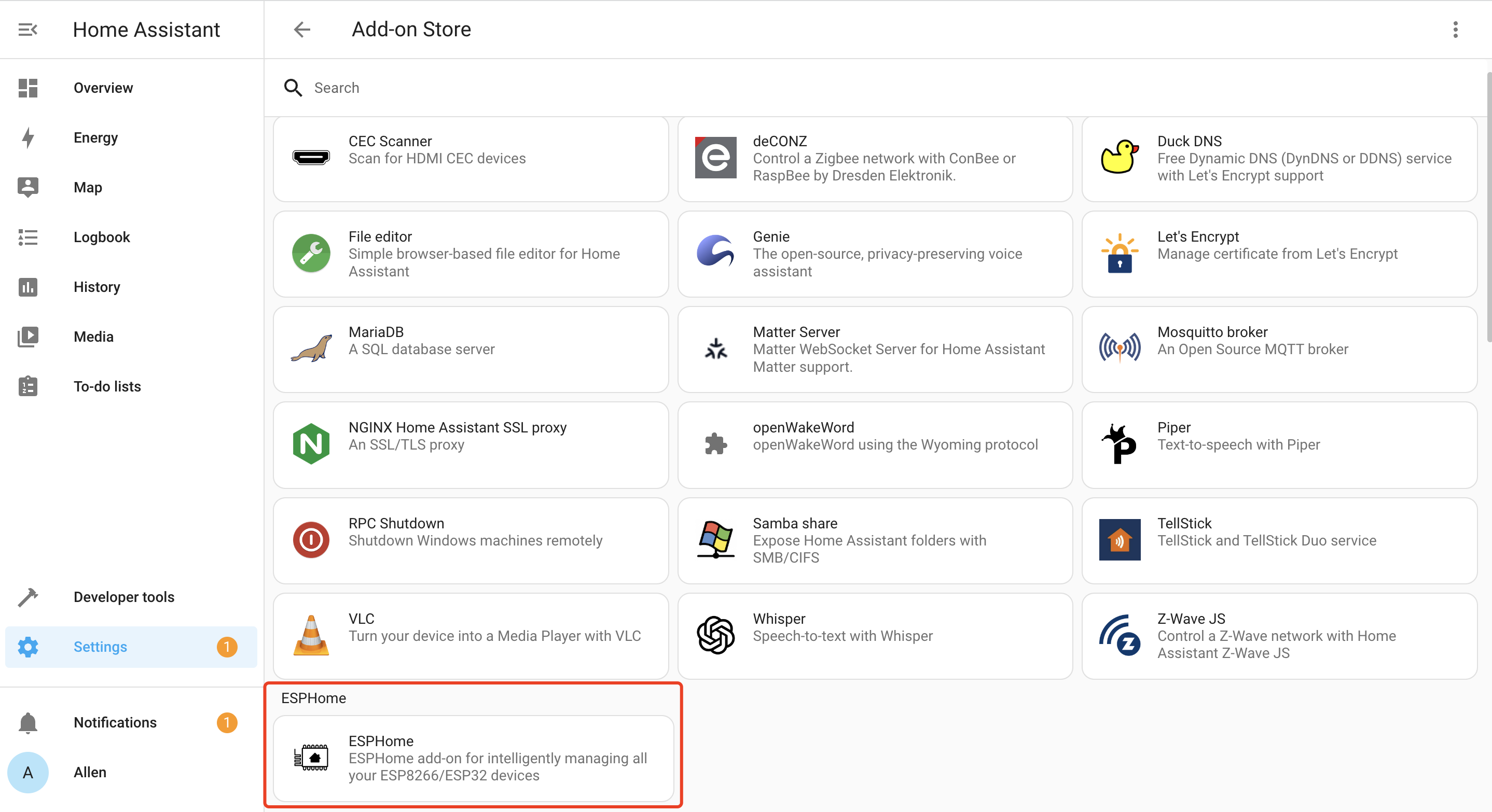
- Step 1. Click INSTALL
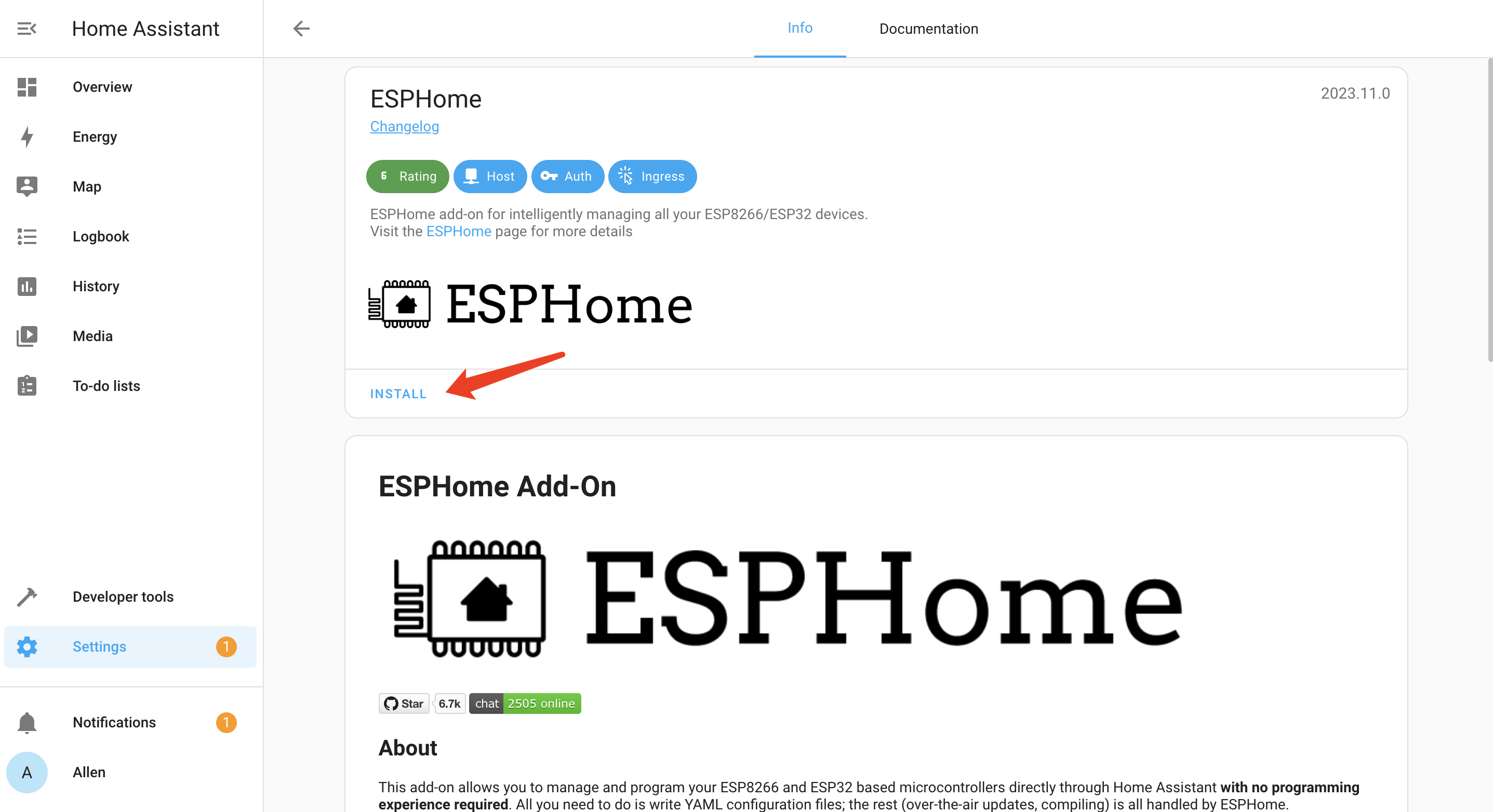
- Step 2. Enable all the options and click START
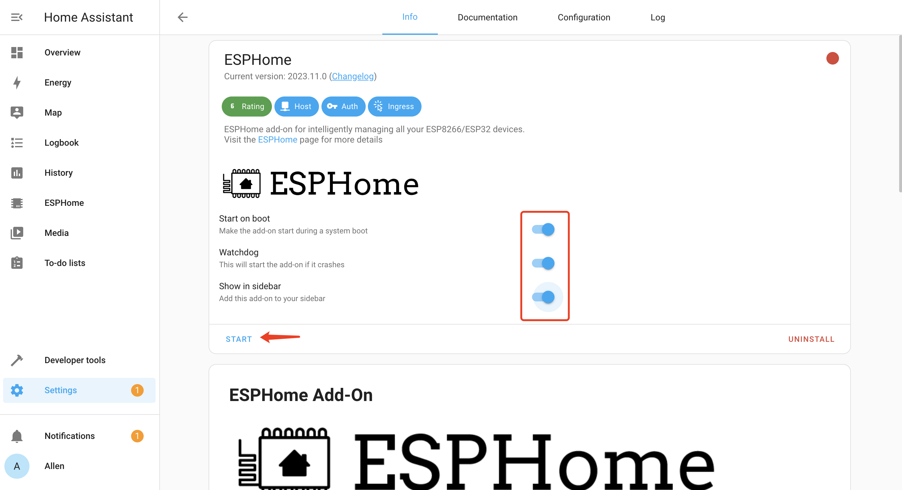
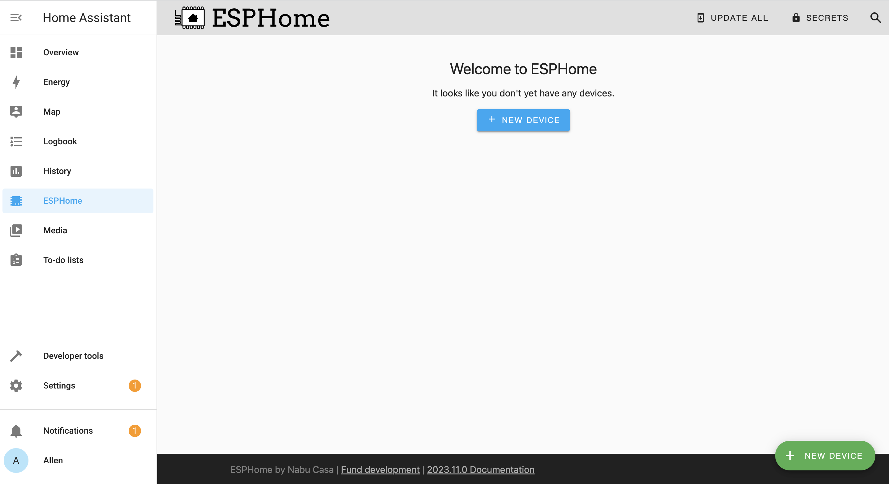
You will see the following window if ESPHome is successfully loaded
Dusk-to-dawn LED lamp
Summary
Let's make a demo of dusk-to-dawn LED lamp, the light will change with the intensity of the light throughout the day.If you're interested, keep reading.

Step 1. Hardware preparation
| XIAO ESP32-C3 | COB LED Driver Board for XIAO | Grove - Digital Light Sensor | Single Ended COB LED Strip |
|---|---|---|---|
| | 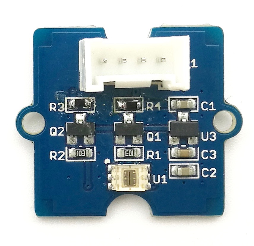 | |
Step 2. Connect Seeed Studio XIAO ESP32-C3, COB LED Driver Board for XIAO and Single Ended COB LED Strip - White as show below:

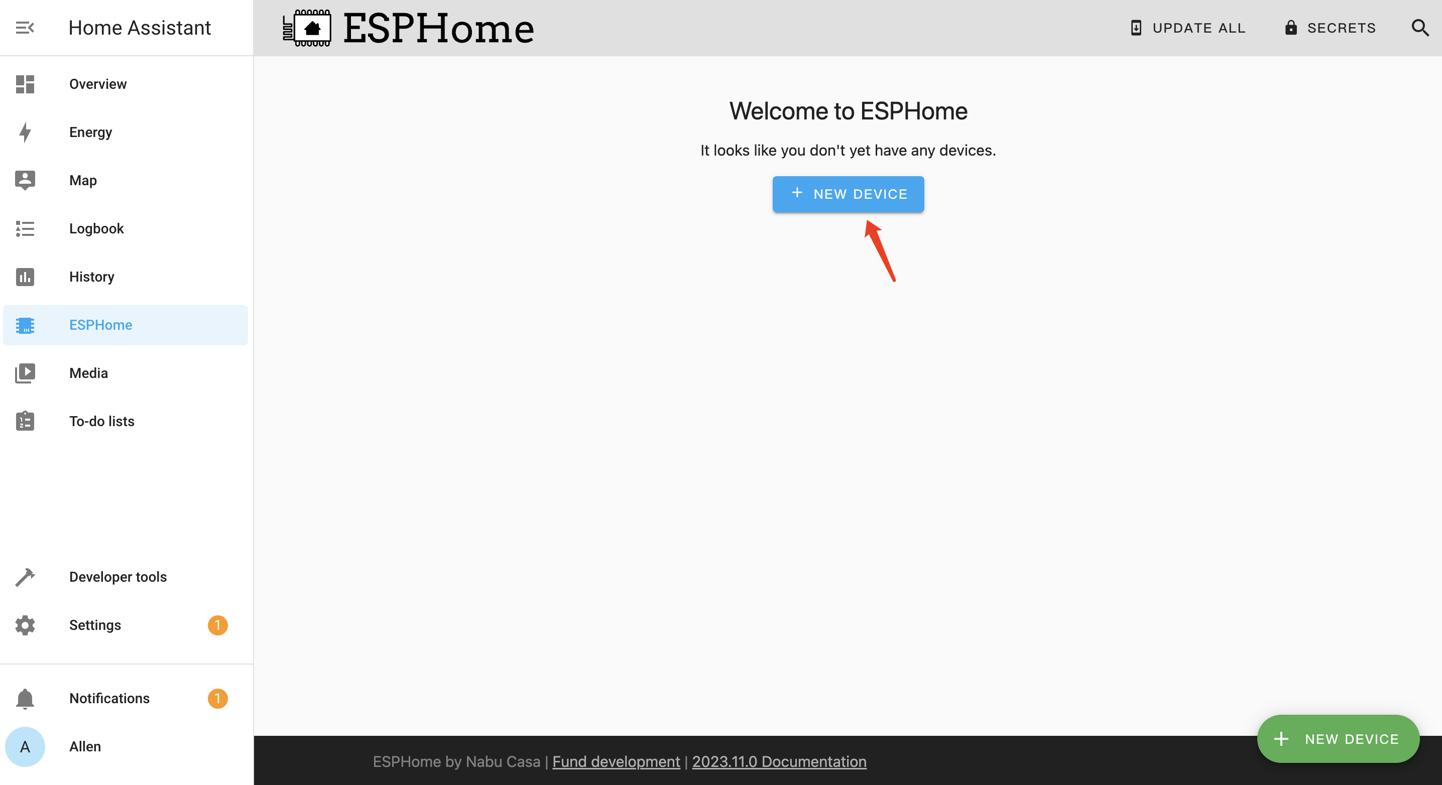
Step 3. Open ESPHome page, and click + NEW DEVICE
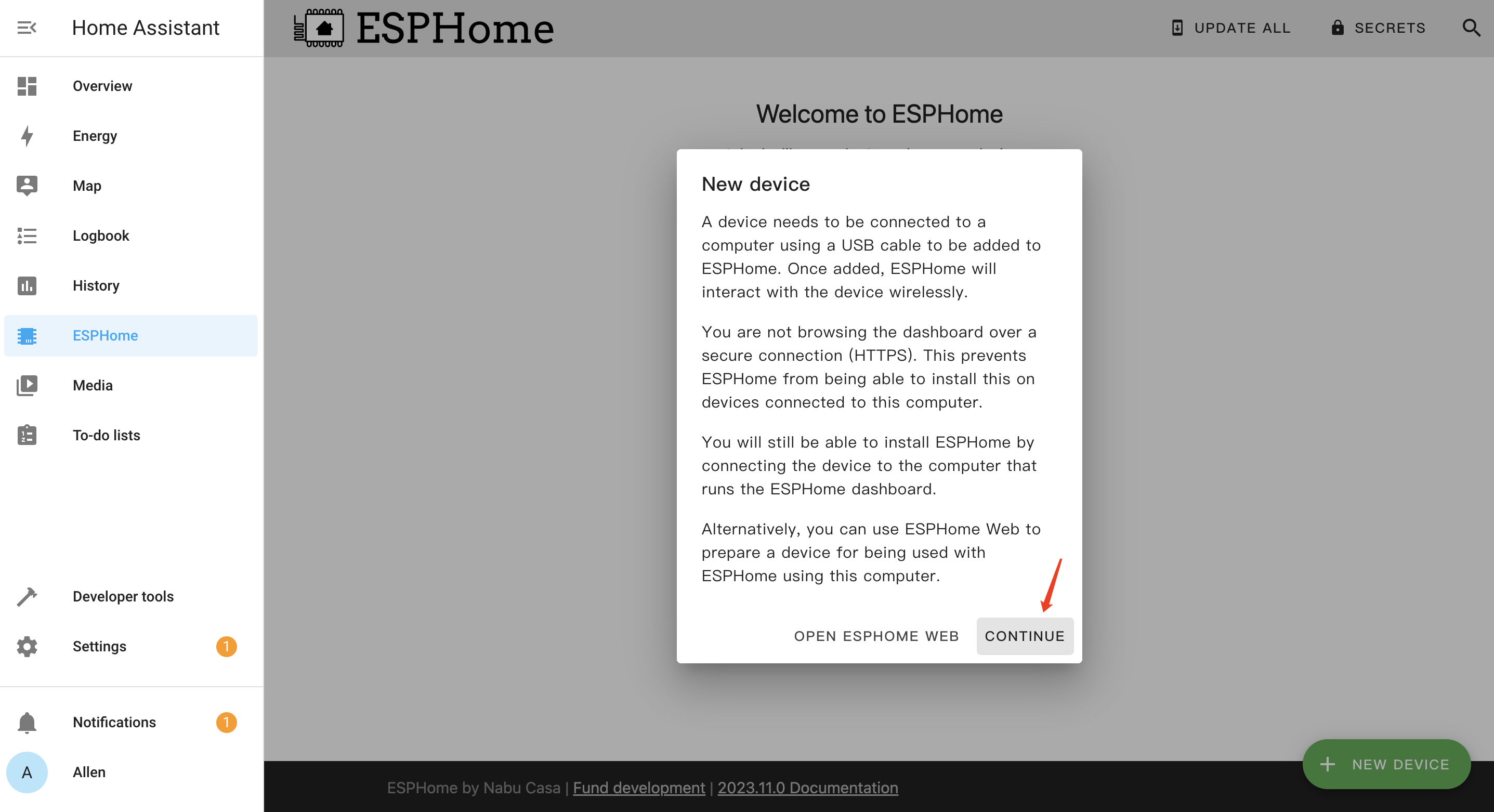
Step 4. Click CONTINUE
Step 5. Enter a Name for the device and enter WiFi credentials such as Network name and Password. Then click NEXT

Step 6. Select ESP32-C3 and click
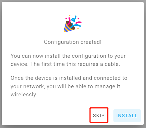
Step 7. Click SKIP because we will configure this board manually
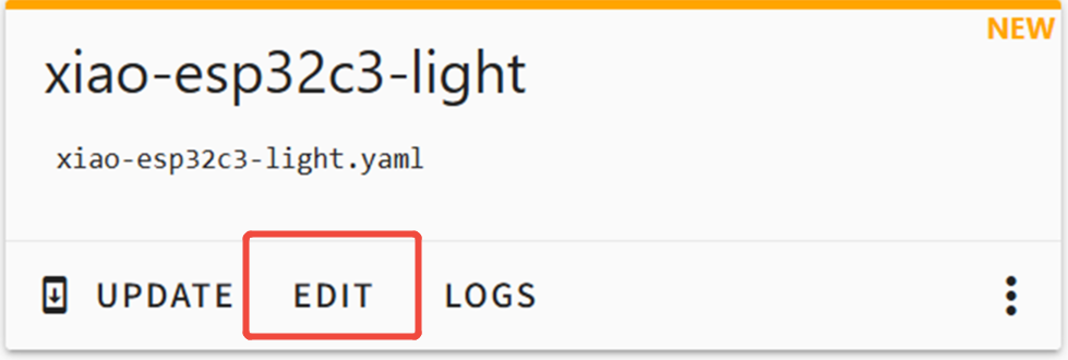
Step 8. Click EDIT under the newly created board
Step 9. The following code is partially copied to the end of the .ymal file. XIAO ESP32-C3 reads the light value from the grove digital light sensor and changes the current level of the D2 pin according to the intensity of the light, so as to control the light bar
# ----------- Additional section (TSL2561, address 0x29) starts -----------
i2c:
  sda: 6
  scl: 7
  scan: true

# Global variables
globals:
  # Record the end timestamp of sensor ignore period (milliseconds)
  - id: ignore_sensor_until
    type: uint32_t
    restore_value: no
    initial_value: '0'
  # Flag: True means current operation is from sensor
  - id: is_robot
    type: bool
    restore_value: no
    initial_value: 'false'

sensor:
  - platform: tsl2561
    name: "Ambient Light"
    address: 0x29
    # Ultra-fast response configuration
    update_interval: 200ms
    integration_time: 101ms
    gain: 1X
    id: lux
    on_value:
      then:
        - lambda: |-
            // 1. Check if in manual control ignore period
            if (millis() < id(ignore_sensor_until)) {
              return;
            }

            // 2. Ultra-fast light control logic
            bool should_turn_on = (x < 180); // Threshold for turning on (dark)
            bool should_turn_off = (x > 220); // Threshold for turning off (bright)

            // Get current light state
            bool is_currently_on = id(light_strip).remote_values.is_on();

            if (should_turn_off && is_currently_on) {
              ESP_LOGD("custom", "Environment brightened (Lux: %.1f), sensor auto-off light", x);

              // Key: Inform Light component this is automated operation
              id(is_robot) = true;

              auto call = id(light_strip).turn_off();
              call.set_transition_length(1000); // 1 second fade
              call.perform();
            }
            else if (should_turn_on && !is_currently_on) {
              ESP_LOGD("custom", "Environment darkened (Lux: %.1f), sensor auto-on light", x);

              // Key
              id(is_robot) = true;

              auto call = id(light_strip).turn_on();
              call.set_transition_length(1000); // 1 second fade
              call.perform();
            }

output:
  - platform: ledc
    pin: 4
    id: pwm_output
    frequency: 1000Hz
    inverted: true

light:
  - platform: monochromatic
    output: pwm_output
    name: "Light Strip"
    id: light_strip
    restore_mode: ALWAYS_OFF
    default_transition_length: 1s

    # Monitor all state changes (on/off/dimming)
    on_state:
      - lambda: |-
          // Check who triggered this state change
          if (id(is_robot)) {
            // If triggered by Sensor:
            ESP_LOGD("custom", "Detected automated operation, not ignoring sensor");
            // Task completed, wait for next cycle
            id(is_robot) = false;
          } else {
            // Triggered by human (HA/Switch):
            ESP_LOGD("custom", "Detected manual operation, ignoring sensor for 30 seconds");
            // Set ignore end time = current time + 30000 milliseconds
            id(ignore_sensor_until) = millis() + 30000;
          }
In the Home Assistant configuration, the numbers for sda, scl and pin always refer to the GPIO numbers, not the silk-screen labels printed on the XIAO board.
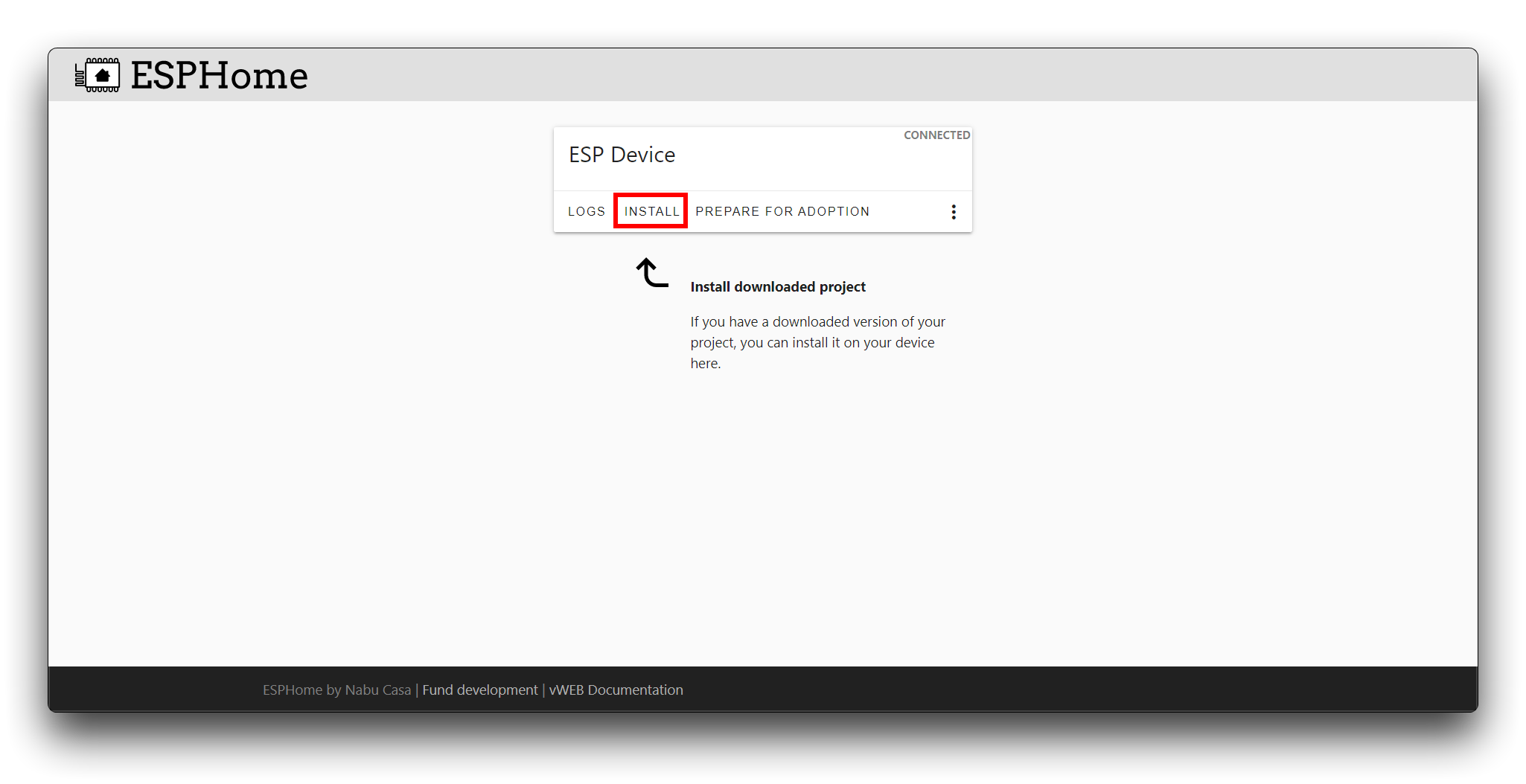
Step 10. Click on the Install button in the top right hand corner. Then select the last item Manual download, Select Modern format

It will then take a long time to download and compile, so please be patient. Once everything is ready, the firmware(XX.bin) will be automatically downloaded to your computer.Compilation successful, as shown in the figure below

Step 11. Using the ESPhome Web tool to upload the firmware to XIAO ESP32, click CONNECT
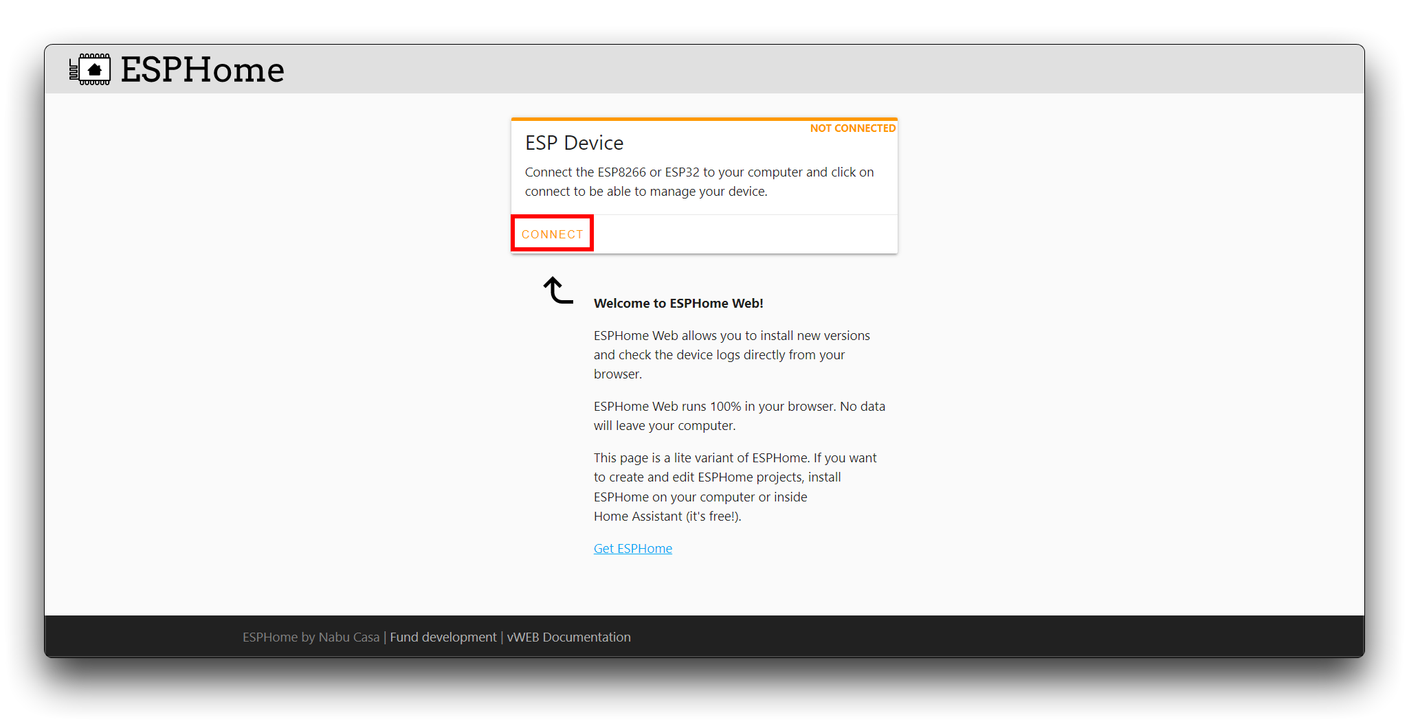
Select the XIAO ESP32 serial port in the popup window, click INSTALL and then select the .bin file downloaded from above steps.
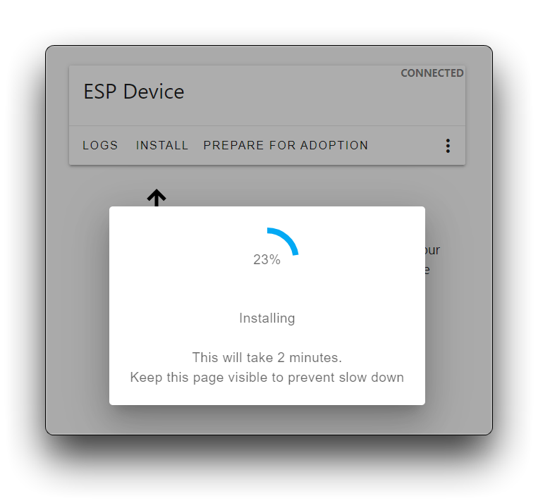
Step 12. Once install successfully, you can see like this:
When the light is strong, the night light turns off,When the light is weak, the night light is on.
Step 13. Once install successfully, Open the log and you will see the feedback messages.


If you like it, you can also follow the above steps to make a night light that is unique to you!
While the board components are rated for -40°C to 85°C, driving all 7 channels at maximum load (Total >1A) will generate significant heat. If installed in a confined space (e.g., inside a sealed plastic model), please ensure passive ventilation to prevent triggering the PMIC's thermal shutdown protection.
Special appreciation
We extend our special thanks to Xinyu for the valuable contribution to the 3D printing work.
The original design demonstrates remarkable creativity and practical value. For those interested in viewing the original design, the demonstration video and the author's homepage are available via the links provided below.
Resources
[PDF] Seeed Studio COB LED Driver Board Schematic
[ZIP] Seeed Studio COB LED Driver Board PCB
[STEP] Seeed Studio COB LED Driver Board 3D Model
FQA
Q1. Why does my board get hot?
- Because there is a hot-swapping phenomenon.When the XIAO is plugged into the USB and then plugged back into the driver board, this process will cause a short circuit in the current conduit of the development board and even burns.
Tech Support & Product Discussion
Thank you for choosing our products! We are here to provide you with different support to ensure that your experience with our products is as smooth as possible. We offer several communication channels to cater to different preferences and needs.