Livbelybot Motor Debugging Assistant for HighTorque use Guide
This manual applies to the High Torque Commissioning Assistant v0.11.1 and above. The High Torque Commissioning Assistant is applicable for motor firmware v3.1.0 and above.
1. Motor Usage Guidelines
🔌 Motor Hardware Wiring
Always ensure power is disconnected before making any connections.
| Specification | Value |
|---|---|
| Rated Voltage | 24VDC |
| Communication | FDCAN (via USB-C module) |
| Motor Models | 5047, 4438, etc. |
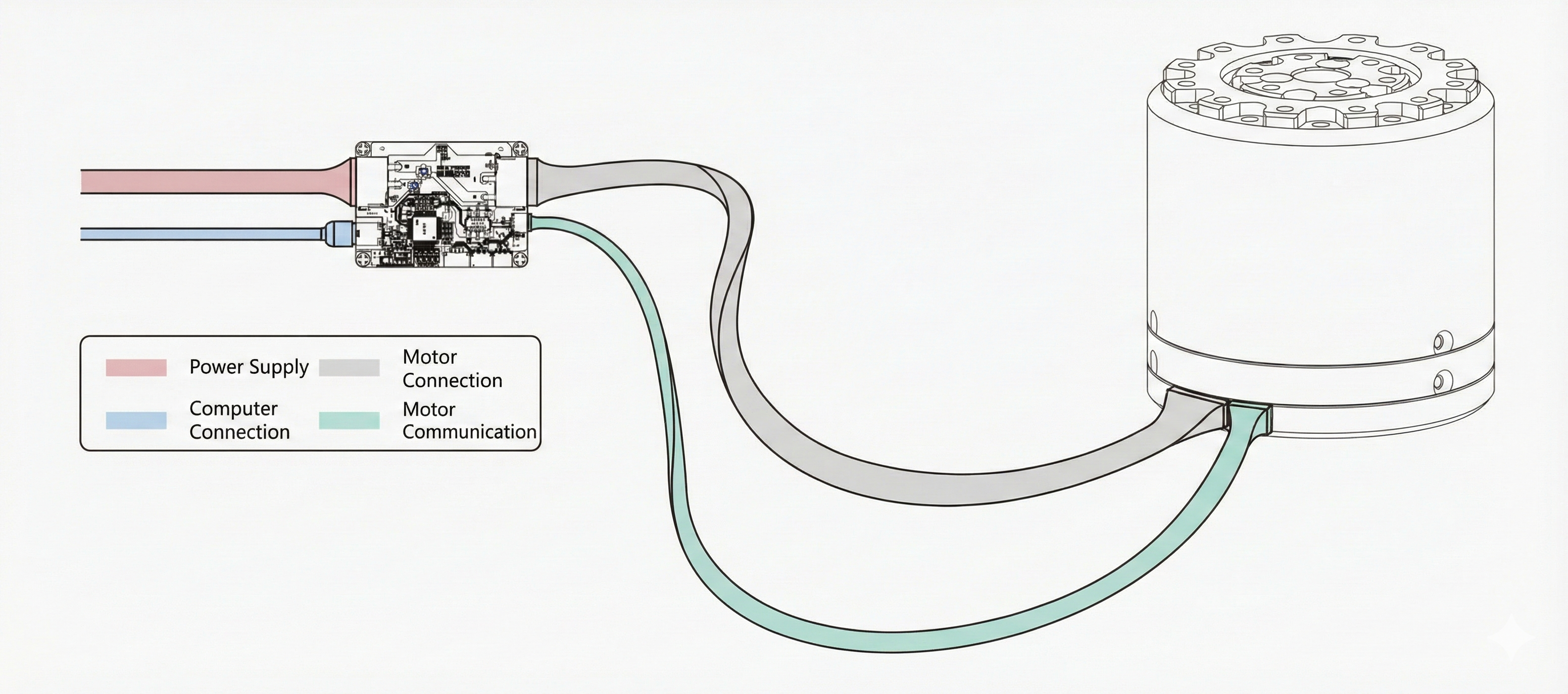
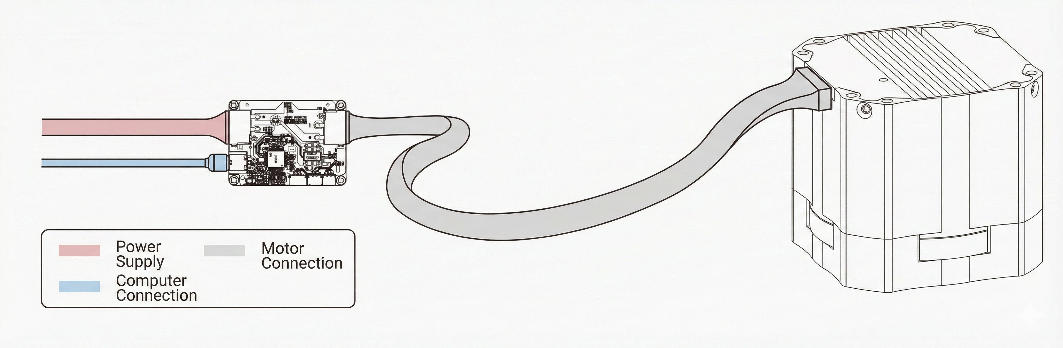
Connection Steps
-
Power Connection 🔌 Connect 24V power supply to the FDCAN module
-
Motor Interface 🔌 Connect Motor XT30 (2+2) interface to FDCAN module using GH1.25-3P cable
-
PC Connection 💻 Connect FDCAN module to computer via USB-C
2. High Torque Motor Commissioning Assistant Usage and Instructions
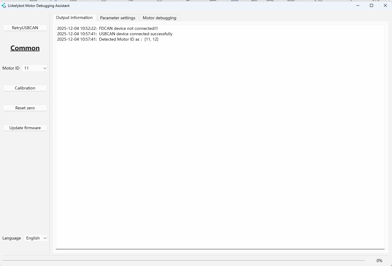
🎛️ Common Functions
| Function | Description |
|---|---|
| 🔄 Reconnect USBCAN Device | Scans and connects the USBCAN device and detects connected motors |
| 🆔 Motor ID | Dropdown selector for currently connected motor |
| ⚙️ Motor Calibration | Re-calibrates the motor (⚠️ Motor must be unloaded) |
| 🎯 Reset Current Motor Zero | Sets current position as zero reference |
| 💾 Update Motor Firmware | Downloads and flashes new firmware to motor |
| 📊 Output Information | Real-time logging console for events and errors |
Motor Calibration must be performed with NO LOAD attached to the motor. Failure to do so will result in inaccurate encoder offset calculation.
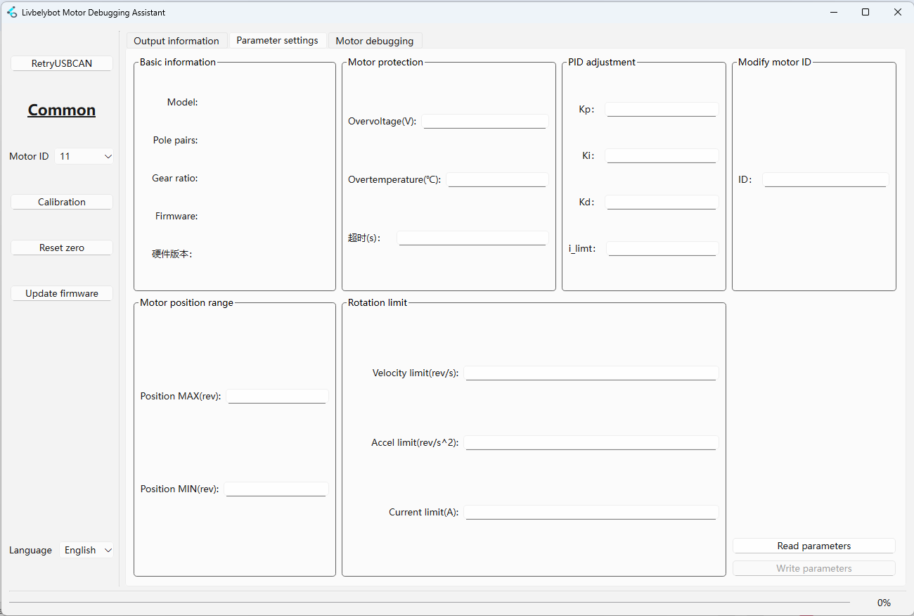
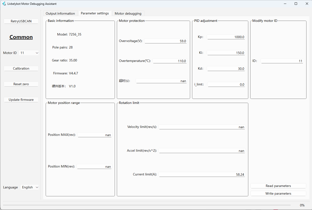
Use Read Parameters to fetch current settings and Write Parameters to save changes to the motor.
| Parameter Group | Description |
|---|---|
| 📋 Basic Information | Displays Model, Pole Pairs, Reduction Ratio, Firmware Version |
| 🛡️ Motor Protection | Over-voltage (V) & Over-temp (°C) limits |
| ⚖️ PID Adjustment | Kp, Ki, Kd coefficients + i_limit (integral limit) |
| 🆔 Modify Motor ID | Changes motor ID (requires re-identification) |
| 📍 Motor Position Range | Position MAX/MIN limits (set to nan for infinite) |
| 🚀 Rotation Limits | Speed (rev/s), Accel (rev/s²), Current (A) limits |
Set values to nan for unlimited operation in Position Range and Rotation Limits sections.
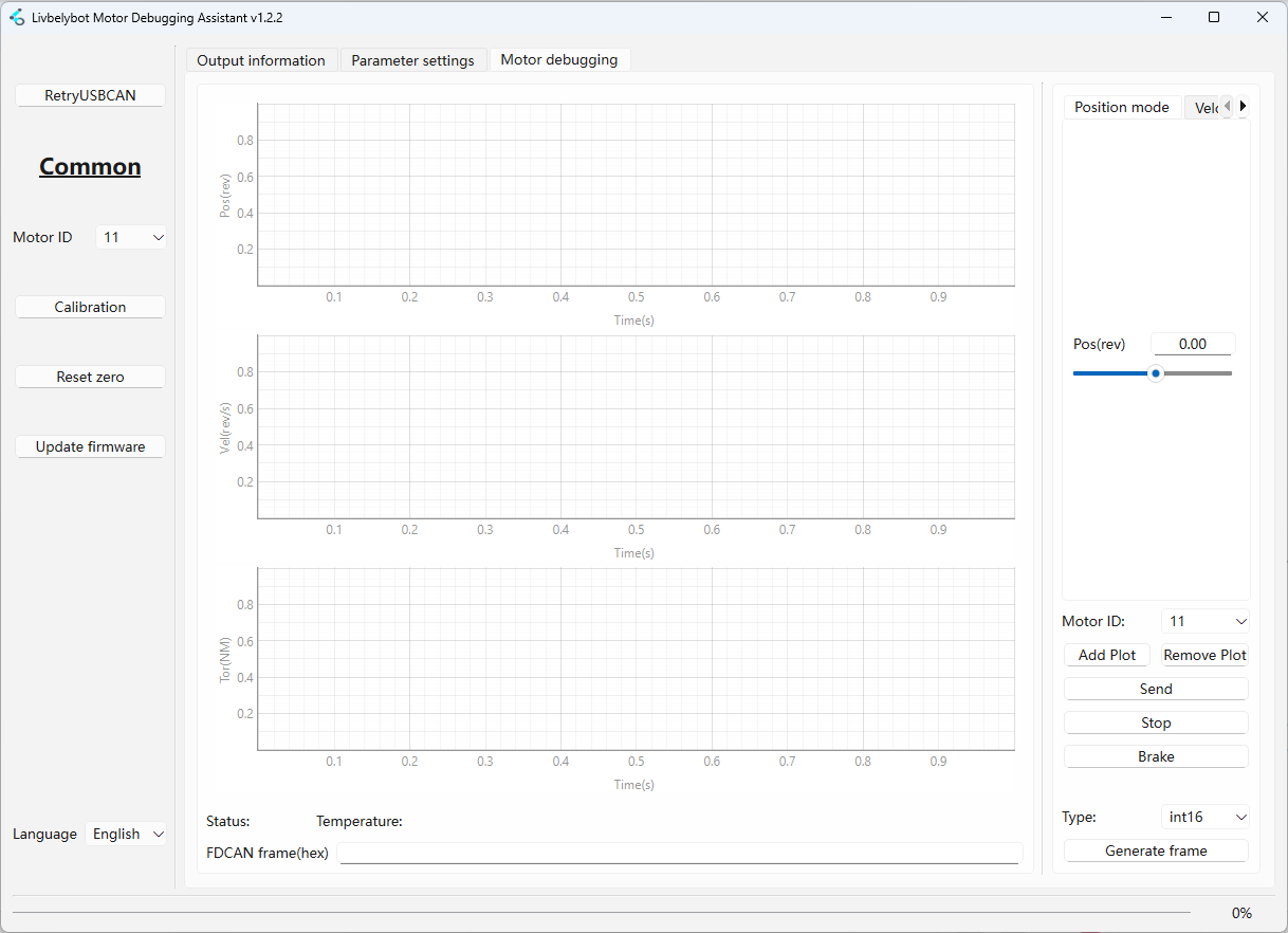
🔧 Motor Debugging
Debug with different running modes (detailed view in Motor Running Modes).
| Feature | Description |
|---|---|
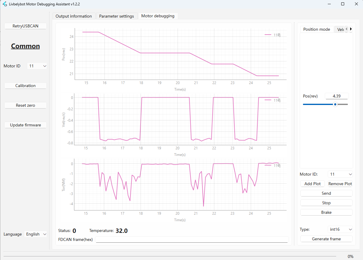
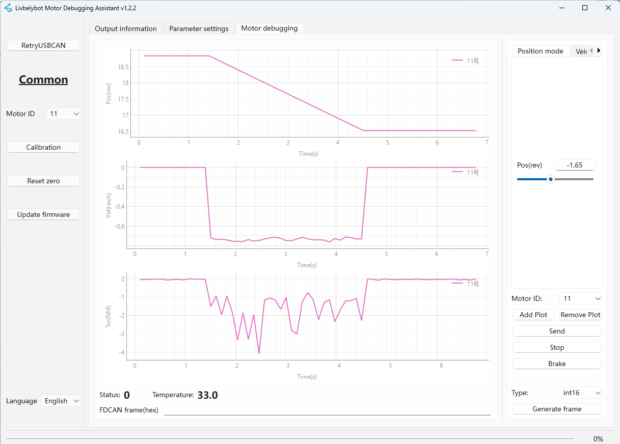
| 📈 Motor Running Mode | Click "Add Waveform" to visualize Position, Speed, Torque, Temperature in real-time |
| 📊 Motor Status | FDCAN frame information (float, int16, int32, CAN frame) |
| 🛠️ Generate Frame | Create custom CAN frames for development |
| 🛑 Stop & Brake | Control motor stopping behavior |
Frame Generation Types
- Numeric Types
- CAN Frame
float, int16, int32
For implementation examples and data type handling, refer to the FDCAN protocol examples in this section
CAN Frame
For CAN frame generation and handling examples, refer to the protocol implementation guides
Stop & Brake Control
| Control | Behavior |
|---|---|
| 🛑 Stop | Disconnects all three phases - motor coasts to stop via inertia |
| ⚡ Brake | Shorts all three phases to ground - motor stops immediately |
🎮 Motor Running Modes
- 1️⃣ Position Mode
- 2️⃣ Velocity Mode
- 3️⃣ Torque Mode
- 4️⃣ Voltage Mode
- 5️⃣ Current Mode
- 6️⃣ Position+Speed+Torque
- 7️⃣ Trapezoidal Control
- 8️⃣ Motion Control
Position Mode 🎯
Provides precise angular control for the motor shaft. Enter the target position in revolutions and click send. The motor will move to the exact specified position using position-loop PID control.
Ideal for: Robotic joints, CNC machines, actuator systems
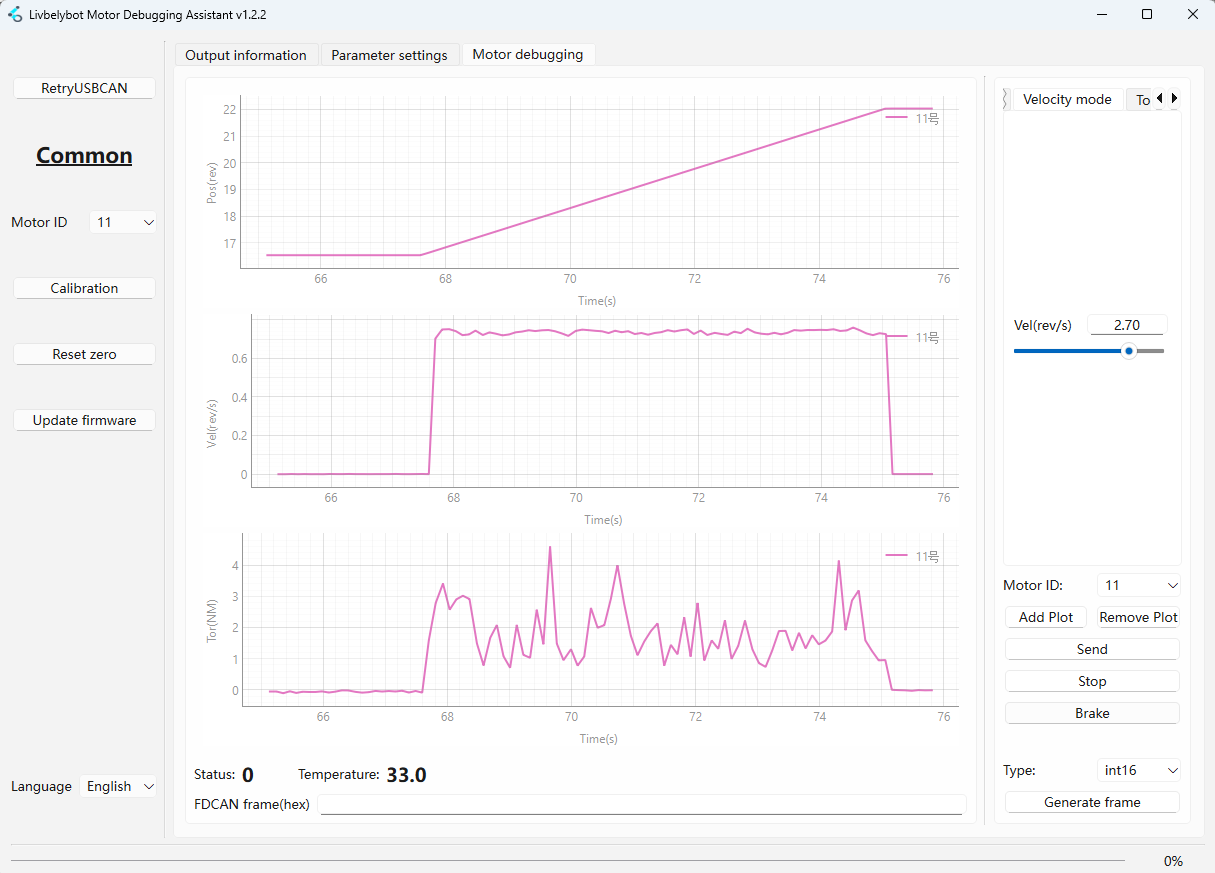
Velocity Mode 🔄
Maintains a constant rotational speed regardless of load variations (within capacity). Input the target velocity in rev/s and click send. The motor will accelerate to the specified velocity using the configured acceleration limit.
Ideal for: Conveyor belts, fans, rotary tables
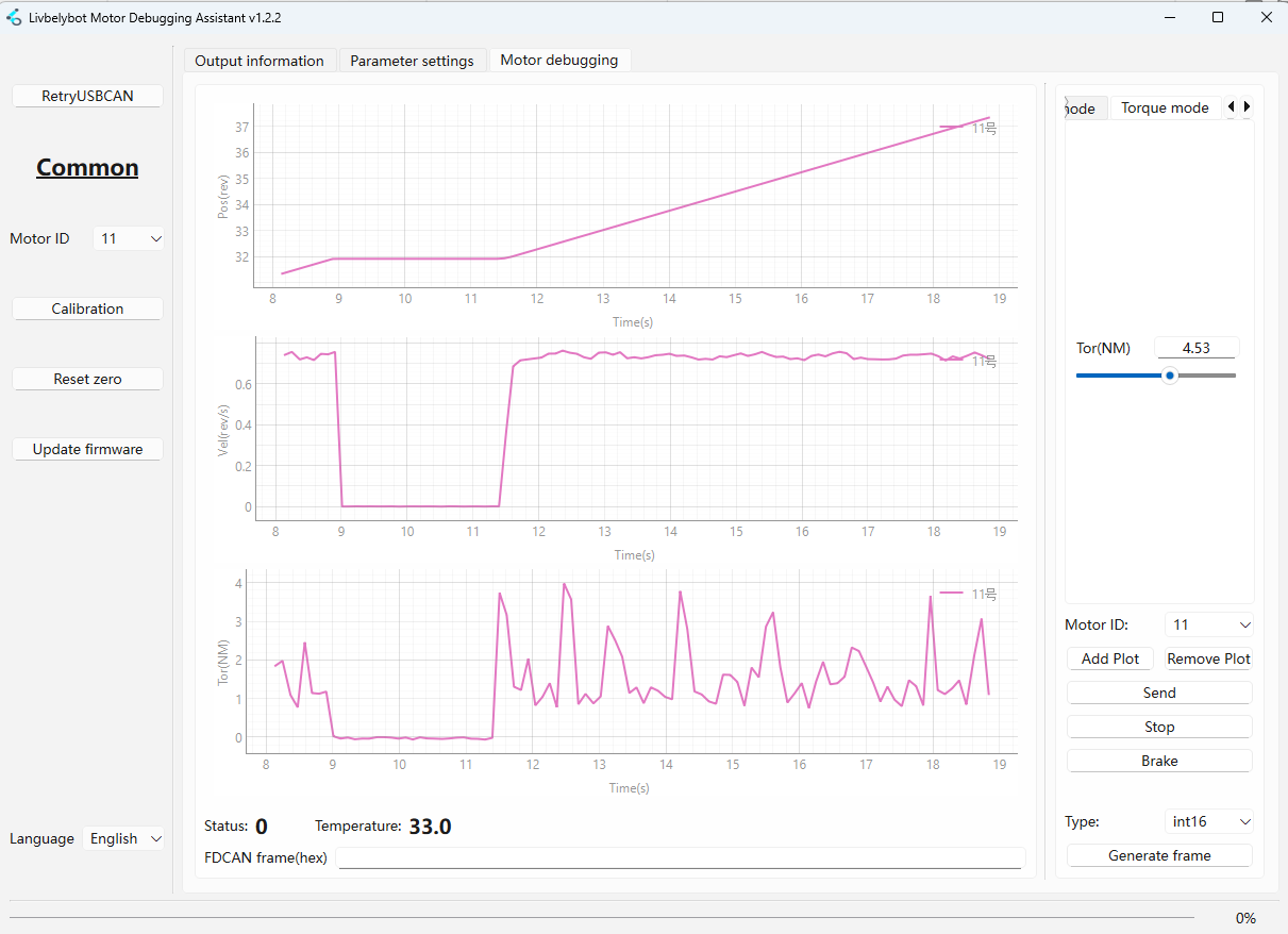
Torque Mode 💪
Controls the output torque directly. The motor will attempt to maintain the specified torque value regardless of speed. If the external resistance exceeds the set torque, the motor will stall to protect the system.
Units: Newton-meters (Nm)
Ideal for: Tensioning systems, press-fit operations, load holding
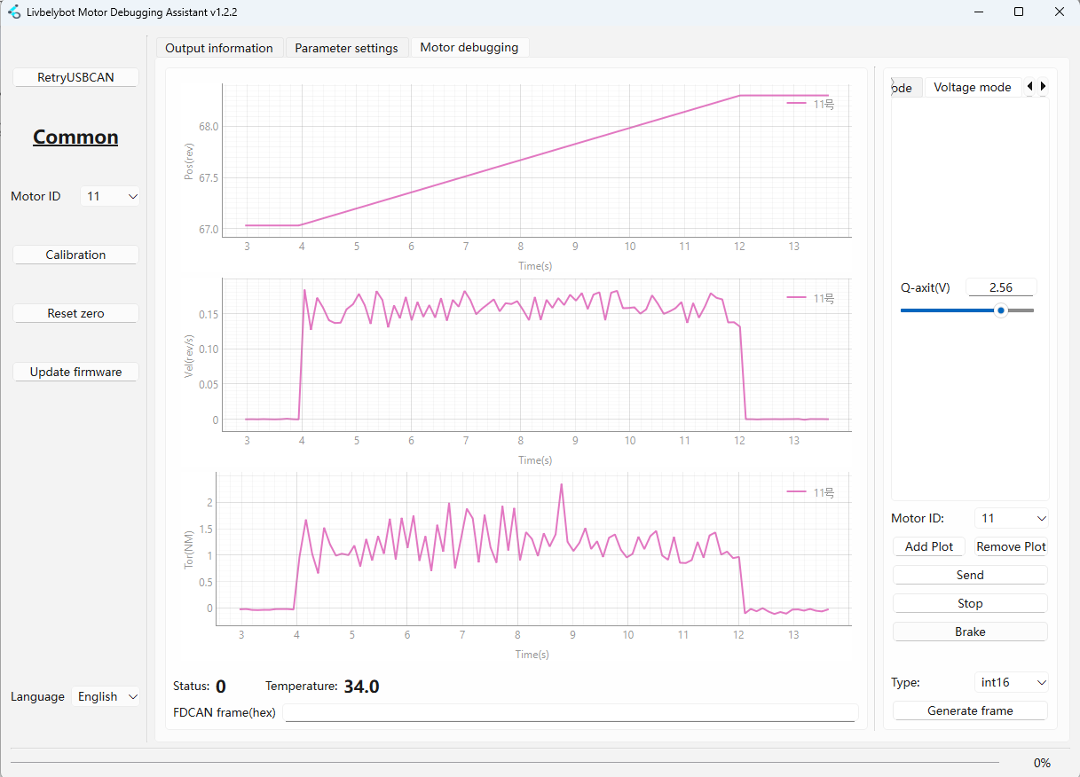
Voltage Mode ⚡
Provides direct control over the Q-axis voltage applied to the motor. This advanced mode allows for custom control algorithms and is typically used in research applications or specialized control systems.
Units: Volts (V)
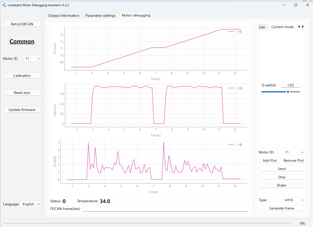
Current Mode 🔋
Controls the Q-axis current flowing through the motor windings. This mode provides more direct control over torque generation than torque mode, as current is the fundamental driver of magnetic field strength.
Units: Amperes (A)
Ideal for: Precise torque control applications
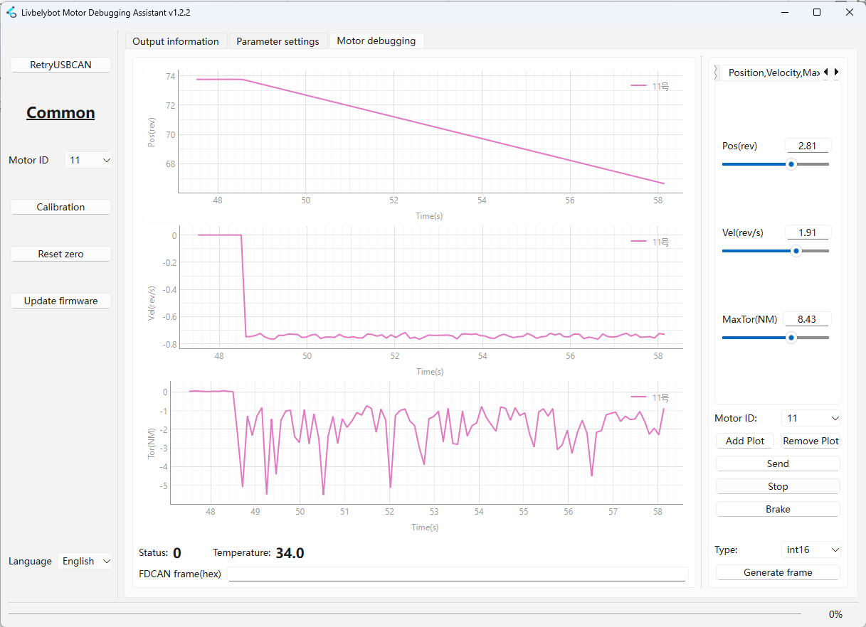
Position, Speed, Maximum Torque 🎛️
Hybrid mode combining position control with velocity and torque limiting for safe, controlled motion. The motor will move to the specified position at the target velocity while ensuring the output torque never exceeds the maximum limit.
Ideal for: Robotic grippers, door actuators, force-limited applications
Set maximum torque to nan if no torque limiting is desired.
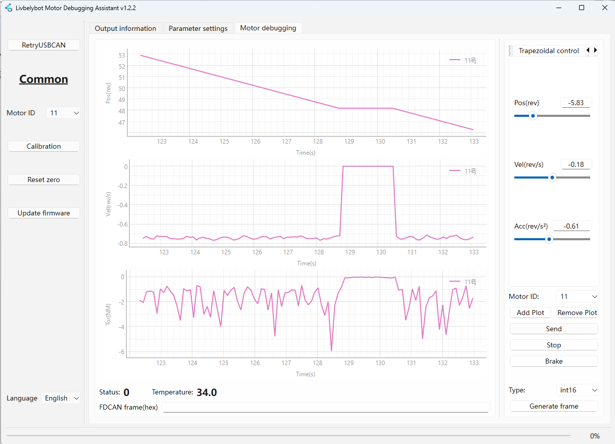
Trapezoidal Control 📈
Generates smooth S-curve trajectories with controlled acceleration and deceleration phases. The motor will: 1) accelerate uniformly to maximum velocity, 2) maintain constant velocity, then 3) decelerate uniformly to stop precisely at the target position.
Ideal for: Pick-and-place operations, CNC positioning, precision automation
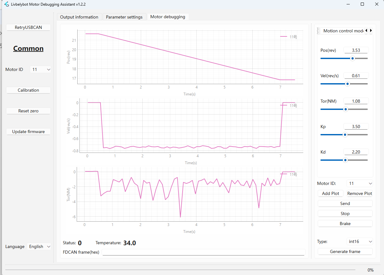
Motion Control Mode 🤖
Advanced PID-based control mode using the formula:
Motor Output Torque = Kp × Position_Error + Kd × Speed_Error + FeedForward_Torque
This mode combines position error (P term) and velocity error (D term) for sophisticated motion control.
Ideal for: High-precision applications, servo presses, force-controlled assembly
3. 🔌 FDCAN Protocol Analysis
This section covers the essential FDCAN protocol information for basic motor control operations. For comprehensive register mapping and advanced protocol details, please refer to the motor control documentation.
Example: int32 Data Frame Velocity Mode
Take the int32 Data Frame Velocity Mode as an example:
01000a0a2000000080204e0000
1️⃣ Sub-frame 1 - Motor Mode Configuration
This sub-frame configures the motor operating mode.
| Field | Value | Description |
|---|---|---|
| 0x01 | Header | Start of first sub-frame |
| Bits 7-4 | 0000 | Write operation to motor registers |
| Bits 3-0 | 0001 | Data type int8_t, 1 data unit |
| 0x00 | Register Address | Motor Mode Setting register |
| 0x0a | Data | Sets motor to Velocity Mode |
2️⃣ Sub-frame 2 - Motion Parameters
This sub-frame configures the motion parameters (position and velocity targets).
| Field | Value | Description |
|---|---|---|
| 0x02 | Header | Start of second sub-frame |
| Bits 7-4 | 0000 | Write operation |
| Bits 3-0 | 0010 | Data type int32_t, 2 data units |
| 0x20 | Register Start | Position Target register (0x20) |
| 0x00 0x00 0x00 0x80 | Position Data | 0x80000000 = Position unlimited/NaN |
| 0x20 0x4e 0x00 0x00 | Velocity Data | 0x00004e20 = 20000 (decimal) |
Velocity Calculation:
- Decimal Value: 20000
- LSB Weight: 0.00001 rev/s per unit
- Target Velocity: 20000 × 0.00001 = 0.2 rev/s
📚 Appendix
⚠️ Motor Error Code Reference
A non-zero value indicates an error. Refer to the table below for specific causes and solutions.
| Code | Error Name | Description | Solution |
|---|---|---|---|
| 32 | 🔧 Calibration Fault | Encoder cannot detect magnet during calibration | Ensure magnet is properly installed; recalibrate with no load |
| 33 | ⚡ Motor Driver Fault | Under-voltage or insufficient current | Check power supply voltage and current capacity |
| 34 | 🔺 Over Voltage | Bus voltage exceeded limit | Verify power supply voltage rating |
| 35 | 📡 Encoder Fault | Encoder reading error | Check encoder connections and wiring |
| 36 | 🚫 Motor Uncalibrated | Motor has not been calibrated | Run calibration procedure with no load |
| 37 | 📊 PWM Cycle Limit Exceeded | Internal firmware error | Contact technical support |
| 38 | 🌡️ Over Temperature | Temperature exceeded maximum limit | Allow motor to cool down; check cooling |
| 39 | 🎯 Out of Bounds | Position control outside defined limits | Adjust position range parameters |
| 40 | 🔋 Low Voltage | Supply voltage too low | Check power supply and connections |
| 41 | ⚙️ Configuration Changed | Critical config changed during operation | Stop motor before changing parameters |
| 42 | 🔄 Angle Invalid | No valid commutation encoder | Check encoder functionality and connections |
| 43 | 📍 Position Invalid | No valid output encoder | Verify output encoder connections |
Tech Support & Product Discussion
Thank you for choosing our products! We are here to provide you with different support to ensure that your experience with our products is as smooth as possible. We offer several communication channels to cater to different preferences and needs.