HighTorque Series Motor User Manual
HighTorque Series Motor Quick Start Guide
This document will introduce how to quickly get started with the HighTorque series motors.

Technical Specifications
Planetary Joint Module Parameter Comparison Table
| Technical Specification Download | HTDW-5047-36-NE | HTDW-4438-32-NE |
|---|---|---|
| Reduction Ratio | 36 | 30 |
| Peak Torque (Nm) | 16 | 6 |
| Rated Torque (Nm) | 4 | 1.5 |
| Stall Torque (Nm) | 24 | 10 |
| Rated Speed (RPM) | 40 | 36 |
| No-load Speed (RPM) | 60 | 75 |
| Rated Power (W) | 17 | 13 |
| Torque Constant (Nm/A) | 0.062 | 0.039 |
| Pole Pairs | 14 | - |
| Rated Voltage (V) | 12-48 | 12-48 |
| Rated Current (A) | 2 | 1 |
| Peak Current (A) | 10 | 5 |
| Torque Control Accuracy | ±10% | ±20% |
| Speed Control Accuracy | ±8% | ±10% |
| Response Time (μs) | ≤200 | ≤200 |
| High-speed Encoder Resolution | 14bit | 14bit |
| Low-speed Encoder Resolution | 12bit | 12bit |
| Communication Baud Rate (Mbps) | 5 | 5 |
| Control Frequency (Hz) | 3k | 3k |
Motor Installation Dimensions
- HTDM-4438-32:

- HTDM-5047-36:

Windows PC Preparation
- Download Motor Debugging Assistant v1.2.1
- Download PC Debugging Manual
- Purchase CAN-USB Driver Board
Protocol Analysis
Protocol Analysis
1.1 CAN Related Instructions
- CAN baud rate:
- Arbitration segment: 1 Mbps
- Data segment: 1 Mbps
- ID: Consists of 16 bits, where 0x7F is the broadcast address.
- High 8 bits: Represent the source address:
- The highest bit is 1: Requires a response, acting as a master switch. Enabling it without sending a query command will return a frame with a data segment length of 0.
- The highest bit is 0: No response is needed.
- The remaining 7 bits: Signal source address.
- Low 8 bits: Represent the destination address:
- The highest bit is 0.
- The remaining 7 bits represent the destination address.
- High 8 bits: Represent the source address:
For example:
- ID: 0x8001
- Signal source address is 0.
- Destination address is 1.
- The highest bit is 1, indicating that a response is required, i.e., the response master switch is turned on.
- ID: 0x100
- Signal source address is 1.
- Destination address is 0.
- The highest bit is 0, indicating no response is needed, i.e., the response master switch is turned off.
1.2 Mode Instructions
1.2.1 Normal Mode (Position and speed cannot be controlled simultaneously)
uint8_t cmd[] = {0x07, 0x07, pos1, pos2, val1, val2, tqe1, tqe2};
The normal protocol is composed of: command bits (2 bytes) + position (2 bytes) + speed (2 bytes) + torque (2 bytes), totaling 8 bytes.
0x07 0x07: Normal mode, which can control speed and torque, or position and torque (see [[#2.1 Normal Mode]]).
The position, speed, and torque data in the protocol are in little-endian mode, meaning the low byte is sent first, followed by the high byte. For example, if pos = 0x1234, then pos1 = 0x34 and pos2 = 0x12.
This mode can be divided into two control methods:
- Position and torque control (at this time, val = 0x8000, indicating no limit).
- Speed and torque control (at this time, pos = 0x8000, indicating no limit).
1.2.2 Torque Mode
uint8_t cmd[] = {0x05, 0x13, tqe1, tqe2};
The torque mode protocol consists of: command bits (2 bytes) + torque (2 bytes).
0x05 0x13: Pure torque mode, followed by two bytes of torque data (see [[#2.3 Torque Mode]]).
The torque data in the protocol is in little-endian mode, i.e., the low byte is sent first, followed by the high byte. For example, if tqe = 0x1234, then tqe1 = 0x34 and tqe2 = 0x12.
1.2.3 Cooperative Control Mode (Position, speed, and torque can be controlled simultaneously)
uint8_t cmd[] = {0x07, 0x35, val1, val2, tqe1, teq2, pos1, pos2};
The cooperative control mode protocol: command bits (2 bytes) + speed (2 bytes) + torque (2 bytes) + position (2 bytes), totaling 8 bytes.
0x07 0x35: Cooperative control mode, which specifies rotating at a specified speed to a specified position and limiting the maximum torque.
In this mode, using the parameter 0x8000 indicates no limit (no limit on speed and torque means the maximum value). For example, val = 5000, tqe = 1000, pos = 0x8000: It means the motor rotates at a speed of 0.5 rotations per second, with a maximum torque of 0.1 NM.
The position, speed, and torque data in the protocol are all in little-endian mode, that is, the low byte is sent first, followed by the high byte. For example, if pos = 0x1234, then pos1 = 0x34 and pos2 = 0x12.
1.3 Motor Status Data Reading
- The protocol for reading the motor status part is the same as the protocol in CAN-FD, with the only difference being that CAN is limited by an 8-byte data segment.
- For the register address and function instructions, please refer to the "Register Function, Motor Operation Mode, Error Code Instructions.xlsx" file.
- Due to the 8-byte data segment limitation of CAN, a single CAN frame can return a limited amount of motor information:
- One float type or int32_t type motor information in a register.
- Three consecutive int16_t type motor information.
- Six consecutive int8_t type motor information.
- The example program provides sample functions for querying motor position, speed, and torque information of int16_t type and motor information parsing (the example program uses a union in C language to directly copy the data from the 3rd to the 8th byte in CAN).
1.3.1 Sending Protocol Instructions
uint8_t tdata[] = {cmd, addr, cmd1, addr1, cmd2, add2};
The general meaning is: Read cmd[0, 1] number of cmd[3, 2] type data from addr.
cmd:
- High four bits [7, 4]: 0001 indicates reading.
- Bits 2-3 [3, 2]: Indicate the type.
- 00: int8_t type.
- 01: int16_t type.
- 10: int32_t type.
- 11: float type.
- Low 2 bits [1, 0]: Indicate the quantity.
- 01: One data.
- 10: Two data.
- 11: Three data.
addr: The starting address to acquire.
Multiple cmds and addrs can be concatenated to read data with discontinuous addresses and different types at one time.
1.3.2 Receiving Protocol Instructions
Assume the acquired data is uint16_t.
uint8_t rdata[] = {cmd, addr, a1, a2, b1, b2, ..., cmd1, addr1, c1, c2, c3, c4}
cmd:
- High four bits [7, 4]: 0010 indicates response.
- Bits 2-3 [3, 2]: Indicate the type.
- 00: int8_t type.
- 01: int16_t type.
- 10: int32_t type.
- 11: float type.
- Low 2 bits [1, 0]: Indicate the quantity.
- 01: One data.
- 10: Two data.
- 11: Three data.
addr: The starting address to acquire.
a1, a2: Data 1, in little-endian mode.
b1, b2: Data 2, in little-endian mode.
1.3.3 Example
- We need to read position, speed, and torque data.
- From the register excel table, we know that the data addresses for position, speed, and torque are: 01, 02, 03.
- From this, we can see that we can read 3 consecutive data starting from address 01. Considering that CAN can transmit a maximum of 8 bytes of data at a time, and cmd + addr occupies two bytes, the data type can at most be int16_t type.
- From the above, the binary of cmd is: 0001 0111, and the hexadecimal is: 0x17.
- It is necessary to start reading from address 01, so addr is 0x01.
- The total data to be sent is uint8_t tdata[] = 1.
The sample code is as follows:
/**
* @brief Read the motor
* @param id
*/
void motor_read(uint8_t id)
{
static uint8_t tdata[8] = {0x17, 0x01};
CAN_Send_Msg(0x8000 | id, tdata, sizeof(tdata));
}

uint8_t cmd[] = {0x17, 0x01};
The overall meaning is: Start from address 0x01 and read 3 int16_t registers (as per the table, the registers at addresses 0x01 to 0x03 represent position, speed, and torque respectively). Therefore, this command is to query the motor's position, speed, and torque information.
0x17: The binary of 0x17[7:4] is 0001: indicating read. The binary of 0x17[3:2] is 01: indicating the data type is int16_t. The binary of 0x17[1:0] is 11: indicating the number of data is 3. 0x01: Start from address 0x01.
Corresponding received data example:
uint8_t rdata[] = {0x27, 0x01, 0x38, 0xf6, 0x09, 0x00, 0x00, 0x00};
0x27: Corresponding to the sent 0x17. 0x01: Start from address 0x01. 0x38 0xf6: Position data: 0xf638, i.e., -2505. 0x09 0x00: Speed data: 0x0009, i.e., 9. 0x00 0x00: Torque data: 0x0000, i.e., 0.
1.4 Motor Stop
Instructions:
- Stop the motor.
- Corresponding to the host computer instruction d stop.
/**
* @brief Stop the motor
*/
void motor_stop(uint8_t id)
{
uint8_t tdata[] = {0x01, 0x00, 0x00};
CAN_Send_Msg(0x8000 | id, tdata, sizeof(tdata));
}
1.5 Reset Motor Zero Position
Instructions:
- Set the current position as the motor's zero position.
- This instruction only modifies it in RAM and needs to be used with the conf write instruction to save it to flash.
- It is recommended to send the conf write instruction about 1s after using this instruction.
void rezero_pos(uint8_t id)
{
uint8_t tdata[] = {0x40, 0x01, 0x04, 0x64, 0x20, 0x63, 0x0a};
CAN_Send_Msg(0x8000 | id, tdata, sizeof(tdata));
HAL_Delay(1000); // It is recommended to delay for 1s
conf_write(id); // Save the settings
}
1.6 Save Motor Settings (conf write)
Instructions:
- Save the motor settings in RAM to flash.
- It is recommended to power cycle the motor after using this instruction.
void conf_write(uint8_t id)
{
uint8_t tdata[] = {0x05, 0xb3, 0x02, 0x00, 0x00};
CAN_Send_Msg(0x8000 | id, tdata, sizeof(tdata));
}
1.7 Read Motor Status
Instructions:
- Read motor position, speed, and torque data once.
- For the parsing of the motor feedback status information data, refer to the code in the interrupt function HAL_FDCAN_RxFifo0Callback in the example.
* @brief Instruction to read motor position, speed, and torque
* @param id Motor ID
*/
void motor_read(CAN_HandleTypeDef *hcan, uint8_t id)
{
static uint8_t tdata[8] = {0x17, 0x01};
can_send(hcan, 0x8000 | id, tdata, sizeof(tdata));
}
1.8 Periodically Return Motor Status Data
Instructions:
- Periodically return motor position, speed, and torque data.
- The returned data format is the same as that obtained using the 0x17, 0x01 instruction (i.e., 1.7 Reading Position Status).
- The period unit is ms.
- The minimum period is 1ms.
- To stop the periodic return of data, set the period to 0 or power off the motor.
- For the parsing of the motor feedback status information data, please refer to the code in the interrupt function HAL_FDCAN_RxFifo0Callback in the example.
void timed_return_motor_status(uint8_t id, int16_t t_ms)
{
uint8_t tdata[] = {0x05, 0xb4, 0x02, 0x00, 0x00};
*(int16_t *)&tdata[3] = t_ms;
CAN_Send_Msg(0x8000 | id, tdata, sizeof(tdata));
}
2. Sample Functions
2.1 Normal Mode
2.1.1 Position Control
/**
* @brief Position control
* @param id Motor ID
* @param pos Position: Unit 0.0001 circle, e.g., pos = 5000 means rotating to the position of 0.5 circle.
* @param torque
*/
void motor_control_Pos(uint8_t id,int32_t pos,int16_t tqe)
{
uint8_t tdata[8] = {0x07, 0x07, 0x0A, 0x05, 0x00, 0x00, 0x80, 0x00};
*(int16_t *)&tdata[2] = pos;
*(int16_t *)&tdata[6] = tqe;
uint32_t ext_id = (0x8000 | id);
CAN_Send_Msg(ext_id, tdata, 8);
}
2.1.2 Speed Control
/**
* @brief Speed control
* @param id Motor ID
* @param vel Speed: Unit 0.00025 rotations/second, e.g., val = 1000 means 0.25 rotations/second
* @param tqe Torque
*/
uint8_t tdata[8] = {0x07, 0x07, 0x00, 0x80, 0x20, 0x00, 0x80, 0x00};
*(int16_t *)&tdata[4] = vel;
*(int16_t *)&tdata[6] = tqe;
uint32_t ext_id = (0x8000 | id);
CAN_Send_Msg(ext_id, tdata, 8);
}
2.3 Torque Mode
/**
* @brief Torque mode
* @param id Motor ID
* @param tqe Torque
*/
void motor_control_tqe(uint8_t id,int32_t tqe)
{
uint8_t tdata[8] = {0x05, 0x13, 0x00, 0x80, 0x20, 0x00, 0x80, 0x00};
*(int16_t *)&tdata[2] = tqe;
CAN_Send_Msg(0x8000 | id, tdata, 4);
}
2.4 Cooperative Control Mode
/**
* @brief Motor position-speed-feedforward torque (maximum torque) control, int16 type
* @param id Motor ID
* @param pos Position: Unit 0.0001 circle, e.g., pos = 5000 means rotating to the position of 0.5 circle.
* @param val Speed: Unit 0.00025 rotations/second, e.g., val = 1000 means 0.25 rotations/second
* @param tqe Maximum torque
*/
void motor_control_pos_val_tqe(uint8_t id, int16_t pos, int16_t val, int16_t tqe)
{
static uint8_t tdata[8] = {0x07, 0x35, 0x00, 0x00, 0x00, 0x00, 0x00, 0x00};
*(int16_t *)&tdata[2] = val;
*(int16_t *)&tdata[4] = tqe;
*(int16_t *)&tdata[6] = pos;
CAN_Send_Msg(0x8000 | id, tdata, 8);
}
2.5 DQ Voltage Mode
Instructions:
- Can control the Q-phase voltage, unit: 0.1v, e.g., vol = 10 means the Q-phase voltage is 1V.
void motor_control_volt(FDCAN_HandleTypeDef *hfdcanx, uint8_t id, int16_t vol)
static uint8_t tdata[7] = {0x01, 0x00, 0x08, 0x05, 0x1b, 0x00, 0x00};
*(int16_t *)&tdata[5] = vol;
can_send(hfdcanx, 0x8000 | id, tdata, sizeof(tdata));
}
2.6 DQ Current Mode
Instructions:
- Can control the Q-phase current, unit: 0.1A, e.g., cur = 10 means the Q-phase voltage is 1A.
void motor_control_cur(FDCAN_HandleTypeDef *hfdcanx, uint8_t id, int16_t cur)
{
static uint8_t tdata[7] = {0x01, 0x00, 0x09, 0x05, 0x1c, 0x00, 0x00};
*(int16_t *)&tdata[5] = cur;
can_send(hfdcanx, 0x8000 | id, tdata, sizeof(tdata));
}
2.7 Brake
Instructions:
- Motor braking, rotating the motor will have damping.
/**
* @brief Motor brake
* @param fdcanHandle &hfdcanx
* @param motor id Motor ID
*/
void set_motor_brake(FDCAN_HandleTypeDef *fdcanHandle, uint8_t id)
static uint8_t cmd[] = {0x01, 0x00, 0x0f};
can_send(fdcanHandle, 0x8000 | id, cmd, sizeof(cmd));
}
2.8 Stop
Instructions:
- The motor stops and loses the force to maintain the position.
/**
* @brief Stop the motor. Note: The motor must be stopped before resetting the zero position, otherwise it will be invalid.
* @param fdcanHandle &hfdcanx
* @param motor id Motor ID
*/
void set_motor_stop(FDCAN_HandleTypeDef *fdcanHandle, uint8_t id)
{
static uint8_t cmd[] = {0x01, 0x00, 0x00};
can_send(fdcanHandle, 0x8000 | id, cmd, sizeof(cmd));
}
3. Instructions for Common Types (Units)
3.1 Current (A)
| Data Type | LSB | Actual (A) |
|---|---|---|
| int8 | 1 | 1 |
| int16 | 1 | 0.1 |
| int32 | 1 | 0.001 |
| float | 1 | 1 |
3.2 Voltage (V)
| Data Type | LSB | Actual (V) |
|---|---|---|
| int8 | 1 | 0.5 |
| int16 | 1 | 0.1 |
| int32 | 1 | 0.001 |
| float | 1 | 1 |
3.3 Torque (Nm)
True torque = k * tqe + d
3.3.1 5046 Torque (Nm)
| Data Type | Slope (k) | Offset (d) |
|---|---|---|
| int16 | 0.005397 | -0.455107 |
| int32 | 0.000528 | -0.414526 |
| float | 0.533654 | -0.519366 |
3.3.2 4538 Torque (Nm)
| Data Type | Slope (k) | Offset (d) |
|---|---|---|
| int16 | 0.004587 | -0.290788 |
| int32 | 0.000445 | -0.234668 |
| float | 0.493835 | -0.473398 |
3.3.2 5047/6056 (Bipolar, 36 Gear Ratio) Torque (Nm)
| Data Type | Slope (k) | Offset (d) |
|---|---|---|
| int16 | 0.004563 | -0.493257 |
| int32 | 0.000462 | -0.512253 |
| float | 0.465293 | -0.554848 |
3.3.3 5047 (Unipolar, 9 Gear Ratio) Torque (Nm)
| Data Type | Slope (k) | Offset (d) |
|---|---|---|
| int16 | 0.005332 | -0.072956 |
| int32 | 0.000533 | -0.034809 |
| float | 0.547474 | -0.150232 |
3.4 Temperature (℃)
| Data Type | LSB | Actual (℃) |
|---|---|---|
| int8 | 1 | 1 |
| int16 | 1 | 0.1 |
| int32 | 1 | 0.001 |
| float | 1 | 1 |
3.5 Time (s)
| Data Type | LSB | Actual (s) |
|---|---|---|
| int8 | 1 | 0.01 |
| int16 | 1 | 0.001 |
| int32 | 1 | 0.000001 |
| float | 1 | 1 |
3.6 Position (rotations)
| Data Type | LSB | Actual (rotations) | Actual (°) |
|---|---|---|---|
| int8 | 1 | 0.01 | 3.6 |
| int16 | 1 | 0.0001 | 0.036 |
| int32 | 1 | 0.00001 | 0.0036 |
| float | 1 | 1 | 360 |
3.7 Speed (rotations/second)
| Data Type | LSB | Actual (rotations/second) |
|---|---|---|
| int8 | 1 | 0.01 |
| int16 | 1 | 0.00025 |
| int32 | 1 | 0.00001 |
| float | 1 | 1 |
3.8 Acceleration (rotations/second²)
| Data Type | LSB | Actual (rotations/second²) |
|---|---|---|
| int8 | 1 | 0.05 |
| int16 | 1 | 0.001 |
| int32 | 1 | 0.00001 |
| float | 1 | 1 |
3.9 PWM Scale (unitless)
| Data Type | LSB | Actual |
|---|---|---|
| int8 | 1 | 1/127 - 0.007874 |
| int16 | 1 | 1/32767 - 0.000030519 |
| int32 | 1 | (1/2147483647) - 4.657^10 |
| float | 1 | 1 |
3.10 Kp, Kd Scale (unitless)
| Data Type | LSB | Actual |
|---|---|---|
| int8 | 1 | 1/127 - 0.007874 |
| int16 | 1 | 1/32767 - 0.000030519 |
| int32 | 1 | (1/2147483647) - 4.657^10 |
| float | 1 | 1 |
C++ Example
C++ control requires an additional CAN-USB driver board. Please refer to livelybot_hardware_sdk

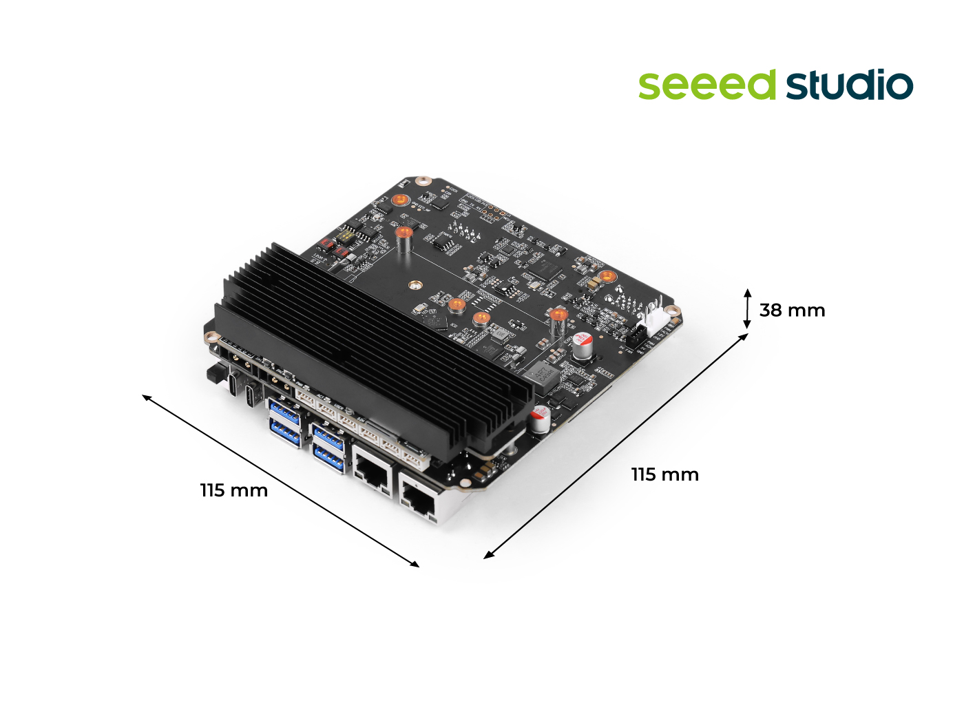
Controlling Motors with reComputer Mini Jetson Orin
Currently, the most commonly used CAN communication interfaces for motors in the market are XT30(2+2) and JST connectors. Our reComputer Mini Jetson Orin and reComputer Robotics devices are equipped with dual XT30(2+2) ports and JST-based CAN interfaces, providing seamless compatibility.
reComputer Mini:

reComputer Robotics
For more details on CAN usage, please refer to this wiki.
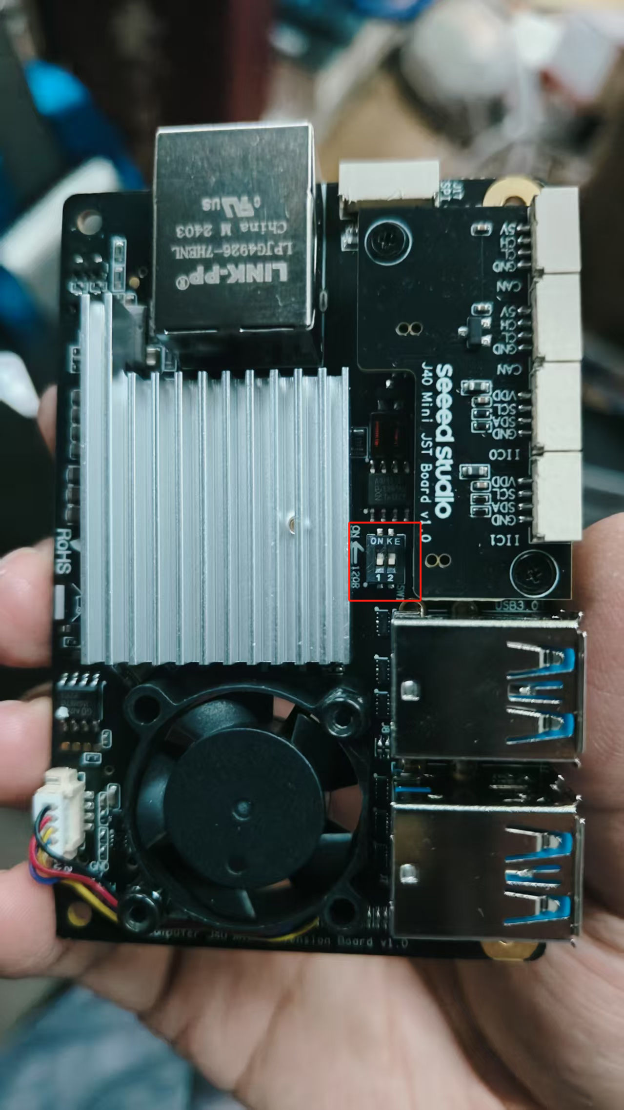
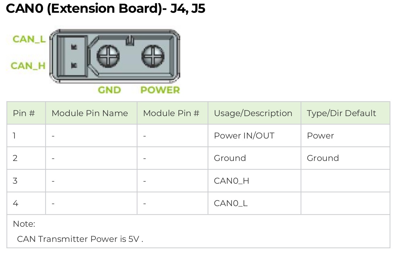
Enabling CAN Interface
Step 1: Before using CAN0 and CAN1, remove the bottom cover and set both 120Ω termination resistors to the ON position.
Step 2: Connect the motor directly to CAN0 of the reComputer Mini via the XT30(2+2) interface.
The H/L pins of the reComputer Mini's CAN interface are opposite to those of the motor, so the H/L connections in the XT30 2+2 harness need to be reversed.

This power solution is only suitable for single-motor learning and testing. For multi-motor applications, please design an independent power board to isolate the Jetson power supply from the motor power supply to avoid large currents passing directly through the Jetson.
Enabling Jetson CAN Communication
Open a terminal and enter the following command to pull the GPIO pin high to activate CAN0:
gpioset --mode=wait 0 43=0
If using the JST interface's CAN1, pull pin 106 high:
gpioset --mode=wait 0 106=0
Keep this terminal open and create a new terminal to configure CAN0:
sudo modprobe mttcan
sudo ip link set can0 type can bitrate 1000000
sudo ip link set can0 up
Python Control
- Install Python Environment
pip install python-can numpy
- Create Script Directory
mkdir -p ~/hightorque/scripts
- Create hightorque_motor.py File
cd ~/hightorque/scripts
touch hightorque_motor.py
Copy the following code into hightorque_motor.py.
hightorque_motor.py
import can
import numpy as np
from time import sleep
from enum import IntEnum

class MotorType(IntEnum):
    """Motor Type Enum"""
    HT5046 = 0  # 5046 Motor
    HT4538 = 1  # 4538 Motor
    HT5047_36 = 2  # 5047/6056 Dual-pole 36 Reduction Ratio
    HT5047_9 = 3  # 5047 Single-pole 9 Reduction Ratio

class ControlMode(IntEnum):
    """Control Mode Enum"""
    NORMAL = 0  # Normal Mode
    TORQUE = 1  # Torque Mode
    COOPERATIVE = 2  # Cooperative Control Mode

class Motor:
    def __init__(self, motor_type: MotorType, slave_id: int, master_id: int):
        """
        Initialize Motor Object
        :param motor_type: Motor Type
        :param slave_id: Slave ID
        :param master_id: Master ID
        """
        self.motor_type = motor_type
        self.slave_id = slave_id
        self.master_id = master_id
        self.position = 0
        self.velocity = 0
        self.torque = 0
        self.temperature = 0

        # Set Torque Conversion Parameters Based on Motor Type
        if motor_type == MotorType.HT5046:
            self.torque_k = 0.005397
            self.torque_d = -0.455107
        elif motor_type == MotorType.HT4538:
            self.torque_k = 0.004587
            self.torque_d = -0.290788
        elif motor_type == MotorType.HT5047_36:
            self.torque_k = 0.004563
            self.torque_d = -0.493257
        elif motor_type == MotorType.HT5047_9:
            self.torque_k = 0.005332
            self.torque_d = -0.072956

    def update_status(self, position: float, velocity: float, torque: float, temperature: float):
        """Update Motor Status"""
        self.position = position
        self.velocity = velocity
        self.torque = torque
        self.temperature = temperature

class MotorControl:
    def __init__(self, channel: str, bitrate: int = 1000000):
        """
        Initialize Motor Controller
        :param channel: CAN Channel
        :param bitrate: CAN Baud Rate
        """
        self.bus = can.interface.Bus(channel=channel, bustype='socketcan', bitrate=bitrate)
        self.motors = {}

    def add_motor(self, motor: Motor):
        """Add Motor to Controller"""
        self.motors[motor.slave_id] = motor

    def __send_data(self, motor_id: int, data: bytes):
        """
        Send CAN Data
        :param motor_id: Motor ID
        :param data: Data to Send
        """
        msg = can.Message(
            arbitration_id=0x8000 | motor_id,
            data=data,
            is_extended_id=True
        )
        self.bus.send(msg)

    def enable(self, motor: Motor):
        """Enable Motor"""
        data = bytes([0x01, 0x00, 0x01])
        self.__send_data(motor.slave_id, data)
        sleep(0.1)

    def disable(self, motor: Motor):
        """Disable Motor"""
        data = bytes([0x01, 0x00, 0x00])
        self.__send_data(motor.slave_id, data)
        sleep(0.1)

    def set_zero_position(self, motor: Motor):
        """Set Motor Zero Position"""
        data = bytes([0x40, 0x01, 0x04, 0x64, 0x20, 0x63, 0x0a])
        self.__send_data(motor.slave_id, data)
        sleep(1.0)  # Wait 1 second
        self.save_settings(motor)

    def save_settings(self, motor: Motor):
        """Save Motor Settings to Flash"""
        data = bytes([0x05, 0xb3, 0x02, 0x00, 0x00])
        self.__send_data(motor.slave_id, data)

    def control_position(self, motor: Motor, position: float, torque: float):
        """
        Position Control
        :param motor: Motor Object
        :param position: Target Position (Unit: 0.0001 turns)
        :param torque: Torque Limit
        """
        pos_bytes = int(position).to_bytes(2, 'little')
        tqe_bytes = int(torque).to_bytes(2, 'little')
        data = bytes([0x07, 0x07]) + pos_bytes + bytes([0x80, 0x00]) + tqe_bytes
        self.__send_data(motor.slave_id, data)

    def control_velocity(self, motor: Motor, velocity: float, torque: float):
        """
        Velocity Control
        :param motor: Motor Object
        :param velocity: Target Velocity (Unit: 0.00025 turns/second)
        :param torque: Torque Limit
        """
        vel_bytes = int(velocity).to_bytes(2, 'little')
        tqe_bytes = int(torque).to_bytes(2, 'little')
        data = bytes([0x07, 0x07, 0x00, 0x80]) + vel_bytes + tqe_bytes
        self.__send_data(motor.slave_id, data)

    def control_torque(self, motor: Motor, torque: float):
        """
        Torque Control
        :param motor: Motor Object
        :param torque: Target Torque
        """
        tqe_bytes = int(torque).to_bytes(2, 'little')
        data = bytes([0x05, 0x13]) + tqe_bytes
        self.__send_data(motor.slave_id, data)

    def control_cooperative(self, motor: Motor, position: float, velocity: float, torque: float):
        """
        Cooperative Control (Position, Velocity, Torque Simultaneous Control)
        :param motor: Motor Object
        :param position: Target Position (Unit: 0.0001 turns)
        :param velocity: Target Velocity (Unit: 0.00025 turns/second)
        :param torque: Torque Limit
        """
        vel_bytes = int(velocity).to_bytes(2, 'little')
        tqe_bytes = int(torque).to_bytes(2, 'little')
        pos_bytes = int(position).to_bytes(2, 'little')
        data = bytes([0x07, 0x35]) + vel_bytes + tqe_bytes + pos_bytes
        self.__send_data(motor.slave_id, data)

    def read_motor_status(self, motor: Motor):
        """Read Motor Status"""
        data = bytes([0x17, 0x01])
        self.__send_data(motor.slave_id, data)
        sleep(0.01)  # Wait for Data Reception

        # Receive and Parse Data
        msg = self.bus.recv(timeout=0.1)
        if msg and msg.arbitration_id == (0x8000 | motor.slave_id):
            data = msg.data
            if len(data) >= 8 and data[0] == 0x27:
                position = int.from_bytes(data[2:4], 'little')
                velocity = int.from_bytes(data[4:6], 'little')
                torque = int.from_bytes(data[6:8], 'little')
                motor.update_status(position, velocity, torque, 0)

    def periodic_read_status(self, motor: Motor, period_ms: int):
        """
        Set Periodic Motor Status Reading
        :param motor: Motor Object
        :param period_ms: Period (milliseconds)
        """
        period_bytes = int(period_ms).to_bytes(2, 'little')
        data = bytes([0x05, 0xb4, 0x02, 0x00]) + period_bytes
        self.__send_data(motor.slave_id, data)

    def close(self):
        """Close CAN Bus"""
        self.bus.shutdown()
- Create hightorque_test.py File
Copy the following code into hightorque_test.py.
hightorque_test.py
#!/usr/bin/env python3
# -*- coding: utf-8 -*-

import time
import math
import numpy as np
from hightorque_motor import Motor, MotorControl, MotorType

# Configuration Parameters
NUM_MOTORS = 2  # Number of Motors to Control
CAN_INTERFACE = "can0"  # CAN Interface Name
CAN_BITRATE = 1000000  # CAN Baud Rate
MOTOR_TYPE = MotorType.HT5047_36  # Motor Type

# Sine Wave Parameters
FREQUENCY = 0.1  # Frequency (Hz)
AMPLITUDE = 2500  # Amplitude (0.0001 turns)
OFFSET = 2500    # Offset to Ensure Positive Position
DURATION = 60.0  # Run Duration (s)

def main():
    # Create Motor Control Object
    controller = MotorControl(channel=CAN_INTERFACE, bitrate=CAN_BITRATE)

    try:
        # Create and Add Motors
        motors = []
        for i in range(NUM_MOTORS):
            motor = Motor(MOTOR_TYPE, slave_id=i+1, master_id=0)
            controller.add_motor(motor)
            motors.append(motor)

            # Enable Motor
            print(f"Enabling Motor {i+1}...")
            controller.enable(motor)
            time.sleep(1)  # Wait for Motor Enable

            # Set Zero Position
            print(f"Setting Motor {i+1} Zero Position...")
            controller.set_zero_position(motor)
            time.sleep(1)

            # Save Settings to Flash
            print(f"Saving Motor {i+1} Settings...")
            controller.save_settings(motor)
            time.sleep(1)

            # Read Initial Status
            controller.read_motor_status(motor)
            print(f"Motor {i+1} Initial Status:")
            print(f"Position: {motor.position * 0.0001:.4f} turns")
            print(f"Velocity: {motor.velocity * 0.00025:.4f} turns/second")
            print(f"Torque: {motor.torque * motor.torque_k + motor.torque_d:.4f} Nm")

        # Start Sine Wave Position Control
        print("\nStarting Sine Wave Position Control...")
        start_time = time.time()
        while time.time() - start_time < DURATION:
            current_time = time.time() - start_time

            # Calculate Sine Wave Position with Offset to Ensure Positive
            position = AMPLITUDE * math.sin(2 * math.pi * FREQUENCY * current_time) + OFFSET

            # Control All Motors
            for motor in motors:
                # Use Position Control Mode with Max Torque of 1000
                controller.control_position(motor, position=int(position), torque=1000)

            # Control Frequency
            time.sleep(0.001)  # 1kHz Control Frequency

    except KeyboardInterrupt:
        print("\nProgram Interrupted by User")
    finally:
        # Disable All Motors
        for motor in motors:
            print(f"Disabling Motor {motor.slave_id}...")
            controller.disable(motor)

        # Close CAN Bus
        controller.close()
        print("CAN Bus Closed")

if __name__ == "__main__":
    main()
- Run hightorque_test.py
python hightorque_test.py
Technical Support and Product Discussion
Thank you for choosing our products! We provide various support channels to ensure you have the best experience.