How to use rs485 and modbus with R1225
Introduction
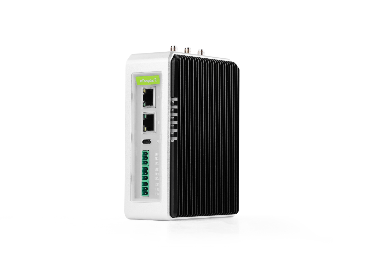
This article mainly introduces how to use the 485 communication function of reComputer R1225, and tests the RS485 and Modbus communication functions.
Getting Start
Before you start this project, you may need to prepare your hardware and software in advance as described here.
Hardware Preparation
| reComputer R1225 |
|---|
 |
Software
- Using modbus poll on your W10 PC.You can also use other modbus testing tools
- Using modbusmechanic on reComputer R1225 and W10 PC.You can also use other modbus testing tools
- Using mobaxterm on your W10 PC.You can also use other serial port testing tools
- You need to download the minicom tool using the following command on the reComputer R1225:
sudo apt-get install minicom
Hardware Configuration
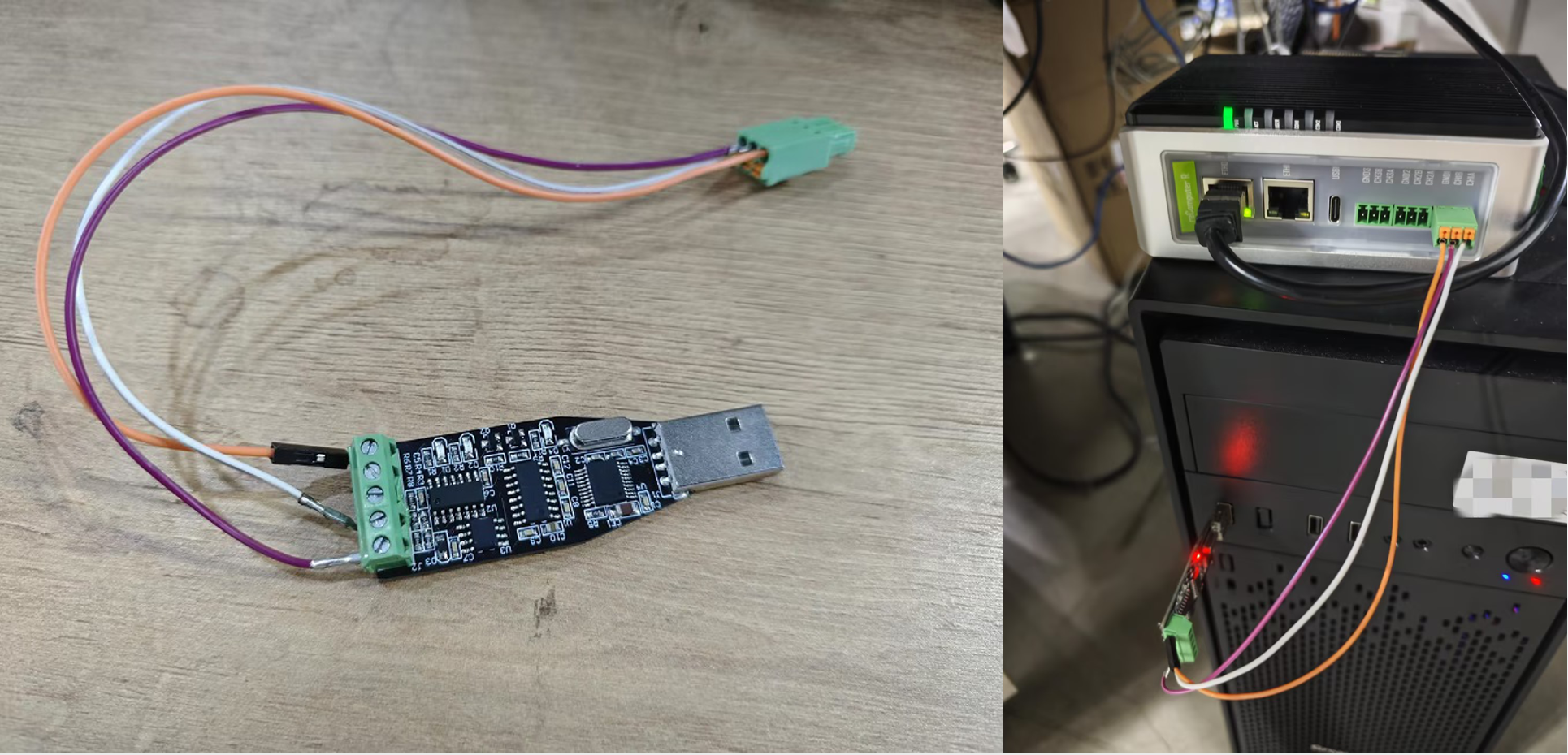
For Modbus RTU, we use an RS485-to-USB converter to connect the R1225 to a Windows 10 PC for testing.
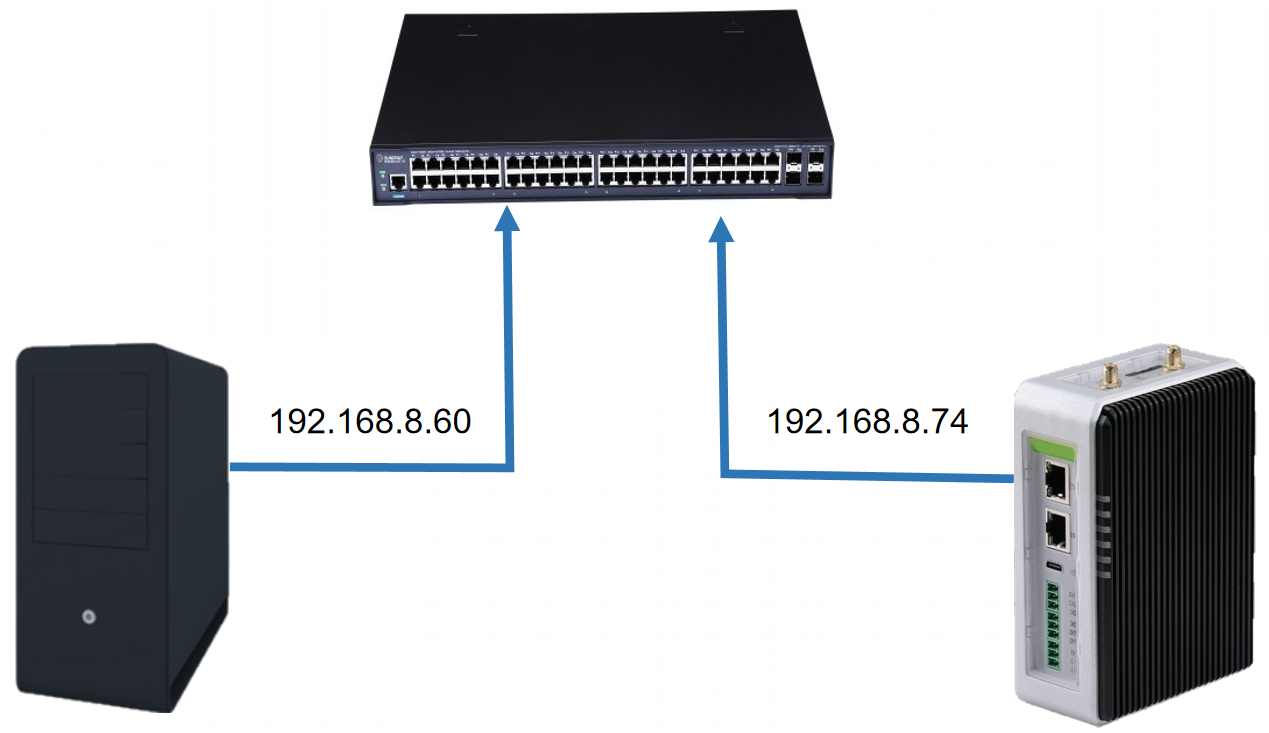
For Modbus TCP, we use Ethernet cables to connect the W10 PC and reComputer R1225 to a switch to ensure that they are on the same network segment.
Method 1: Using the Command-Line Interface (CLI)
Steps to use Modbus RTU testing
Installing and configuring minicom
Install minicom on both your host computer and reComputer R1225 with command below:
sudo apt install minicom
Open a terminal,and input command like below:
sudo minicom -D /dev/ttyAMA*
The ttyAMA* should be ttyAMA2, ttyAMA3 or ttyAMA4 depends on which RS485 you use.
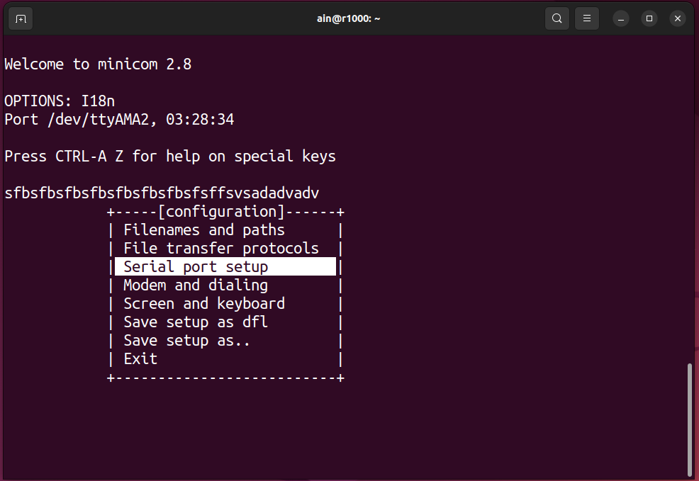
And then type Ctal+A then type Z you will see minicom like below:
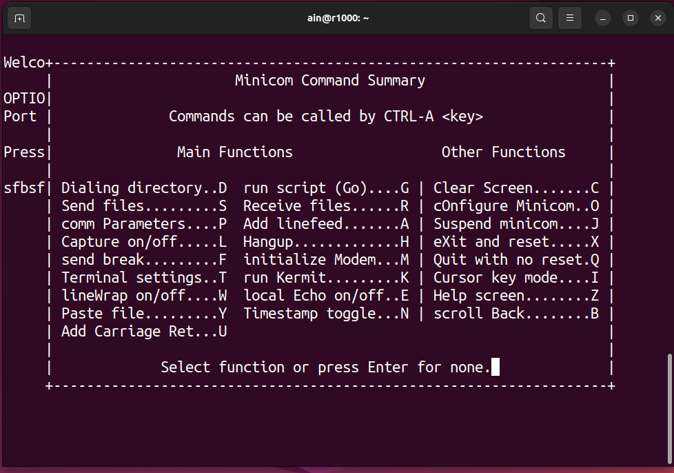
Type o to configure minicom, and select Serial port setup you will see like below:
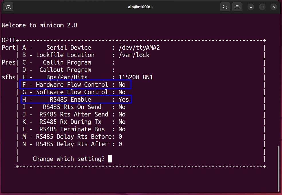
And the type F and H to make minicom to RS485 model, the result will show as below:
Finally, select Exit and type Enter to exit configure, like below:

Step 1: Testing RS485 Functionality
Enter the following script on reComputer R1225 to open the minicom software
minicom -D /dev/ttyAMAx -b 9600
Parameter Description:
-D: Enter the device number you want to open in the field below.the device number needs to be the newly created device number.
-b: Enter the baud rate below
Then open MobaXterm on the W10 PC, create a new serial port terminal, select the serial port number, and the baud rate is 9600; finally, you can perform two-way communication with RS485. As shown in the figure, the content entered on the reComputer R1000 can be sent to via RS485. In W10 PC, the content entered on W10 PC can also be sent to reComputer R1225, and the two-way communication is normal
Step 2: Test the R1225 as a Modbus slave
Open the ModbusMechanic software on reComputer R1225, select the device number and baud rate, then click on the simulated slave function in the upper left corner to add two coils; then open Modbus poll in W10 as the master station to read the coils of the slave station. Then open the display window of Modbus poll, and you can see that the sending and receiving messages of Modbus RTU are normal.
Step 3: Test the R1225 as a Modbus master
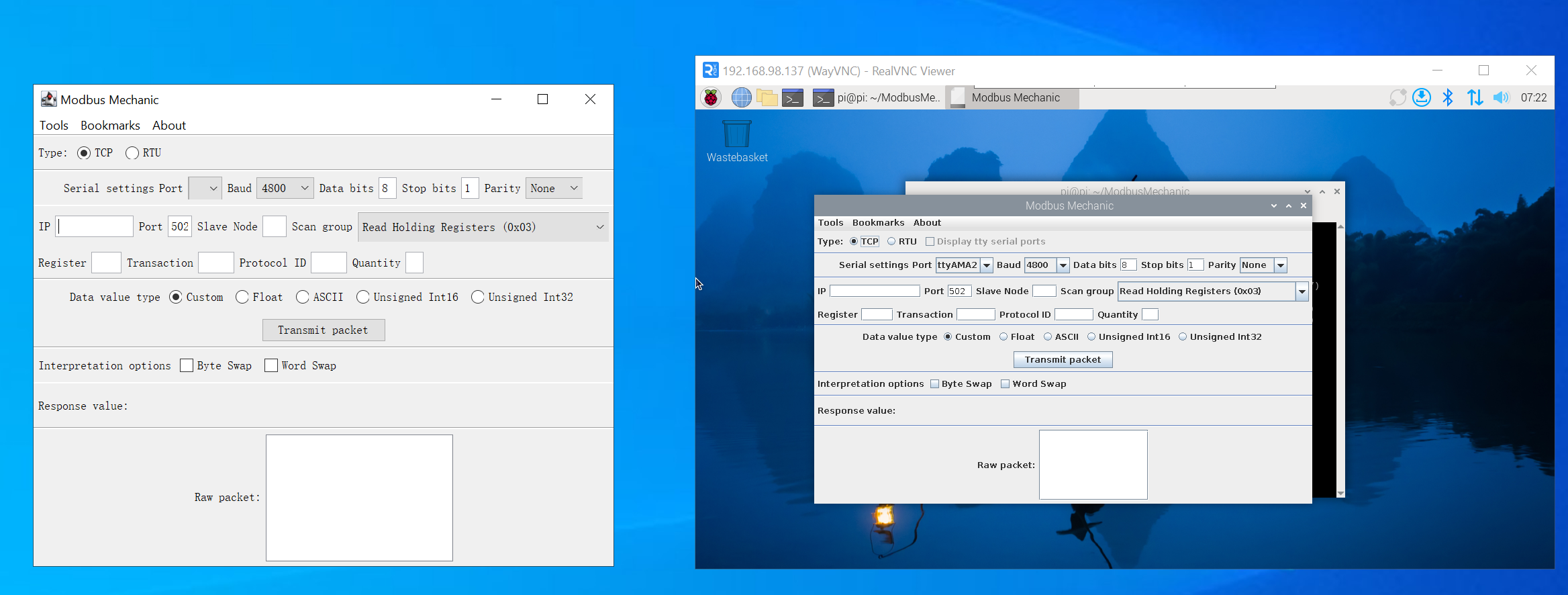
pen the ModbusMechanic software on both reComputer R1225 and W10 PC, and select the device number and baud rate. W10 PC refers to the third step of setting. Select Read Coils(0x01) on reComputer R1000 to read the coil of the slave, set Slave Node to 1, Register select the address you want to read, and finally click Transmit packet.
Steps to use the Modbus TCP testing
Step 1: Open modbusmechanic on Win10 PC and R1000
Step 2: Test the R1225 as a Modbus TCP host
Click Tool => Start Slave Simulator on W10 PC, select TCP for TYPE, select 1 for Slave ID, and then add Coils; then enter IP in R1225, and select Read Coil for Scan group. Enter Slave Node and Register, and finally click Transmit packet. You can see that the slave data has been successfully read.
Step 3: Test the R1225 as a Modbus TCP slave
Refer to the second step for configuration. You can see that R1225 can read data normally as a slave.
Running the Modbus TCP slave program in R1000 needs to listen to the 502 port, which may require sudo permissions. If your application cannot listen to the 502 port, please try to add permissions to it.
Method 2: Using the Graphical User Interface (GUI)
RS485 Parameter Configuration
Follow the Quick Start guide to access the SenseCAP Gateway OS web interface.
Step 1: Login Luci
Input the IP Address of your device in a browser to enter the Luci page. Then input your device username and password to login, and click the Login button.

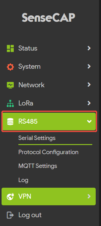
**Step 2 Click on RS485 - Serial Settings
The parameter settings for all three 485 channels of the R1225 are integrated here.
First,select the channel you want to use (CH1, CH2, CH3);
Next, configuration parameters: baud rate, data bits, stop bits, parity, flow control, and read timeout.
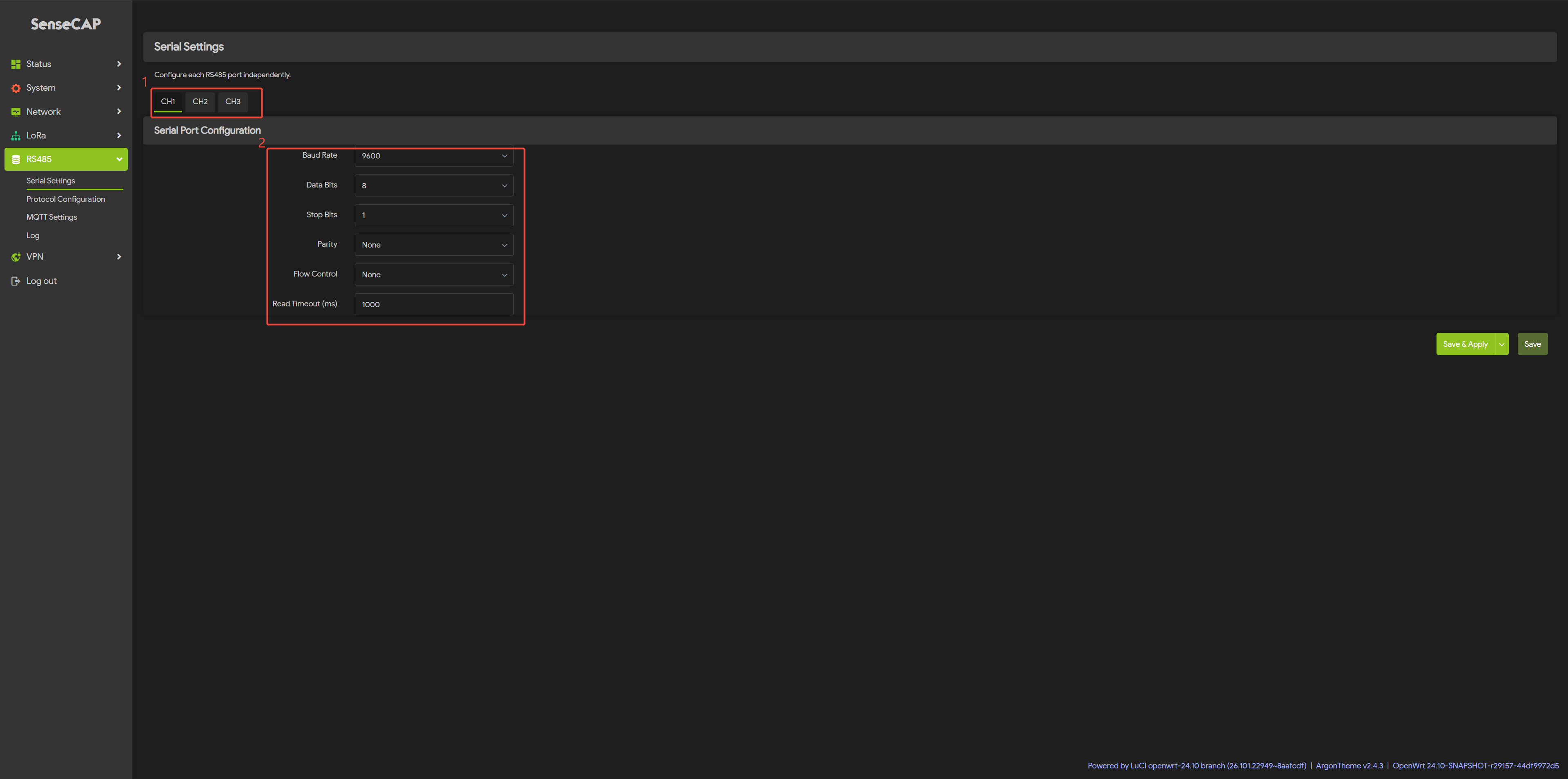
Step 3:Click Save & Apply to apply your settings
Modbus RTU Parameter Configuration
After configuring the parameters for the three RS-485 ports (the default settings are ‘9600, 8, 1, N’), you can proceed with the Modbus RTU configuration.
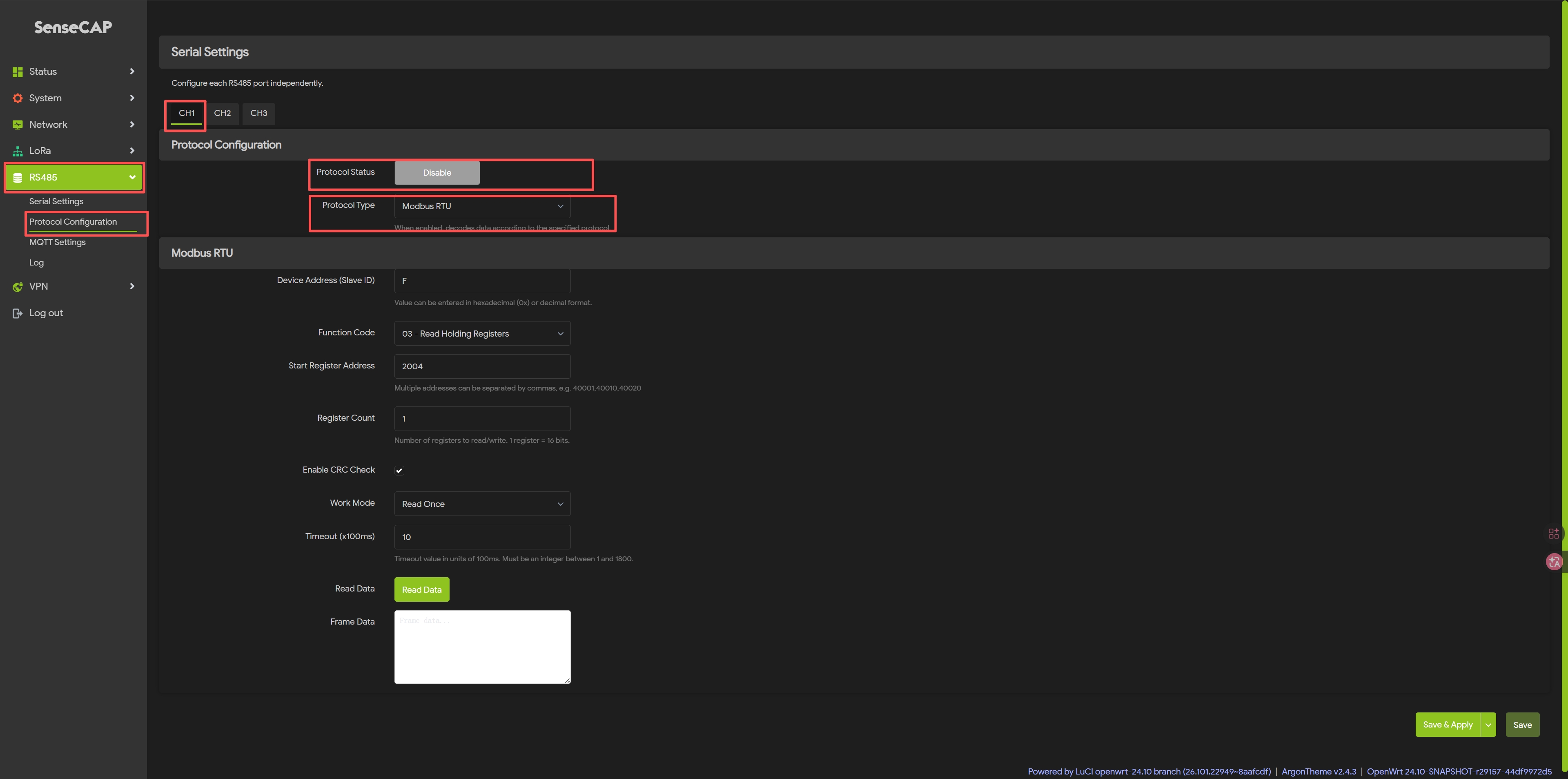
Step 4: Click on RS485 - Protocol Configuration
Select the channel you want to debug (CH1, CH2, CH3).
Select “Enable” for the protocol status and “Modbus RTU” for the protocol type.
Once enabled, you will see the Modbus RTU settings screen; simply configure it according to the datasheet for the connected sensor.
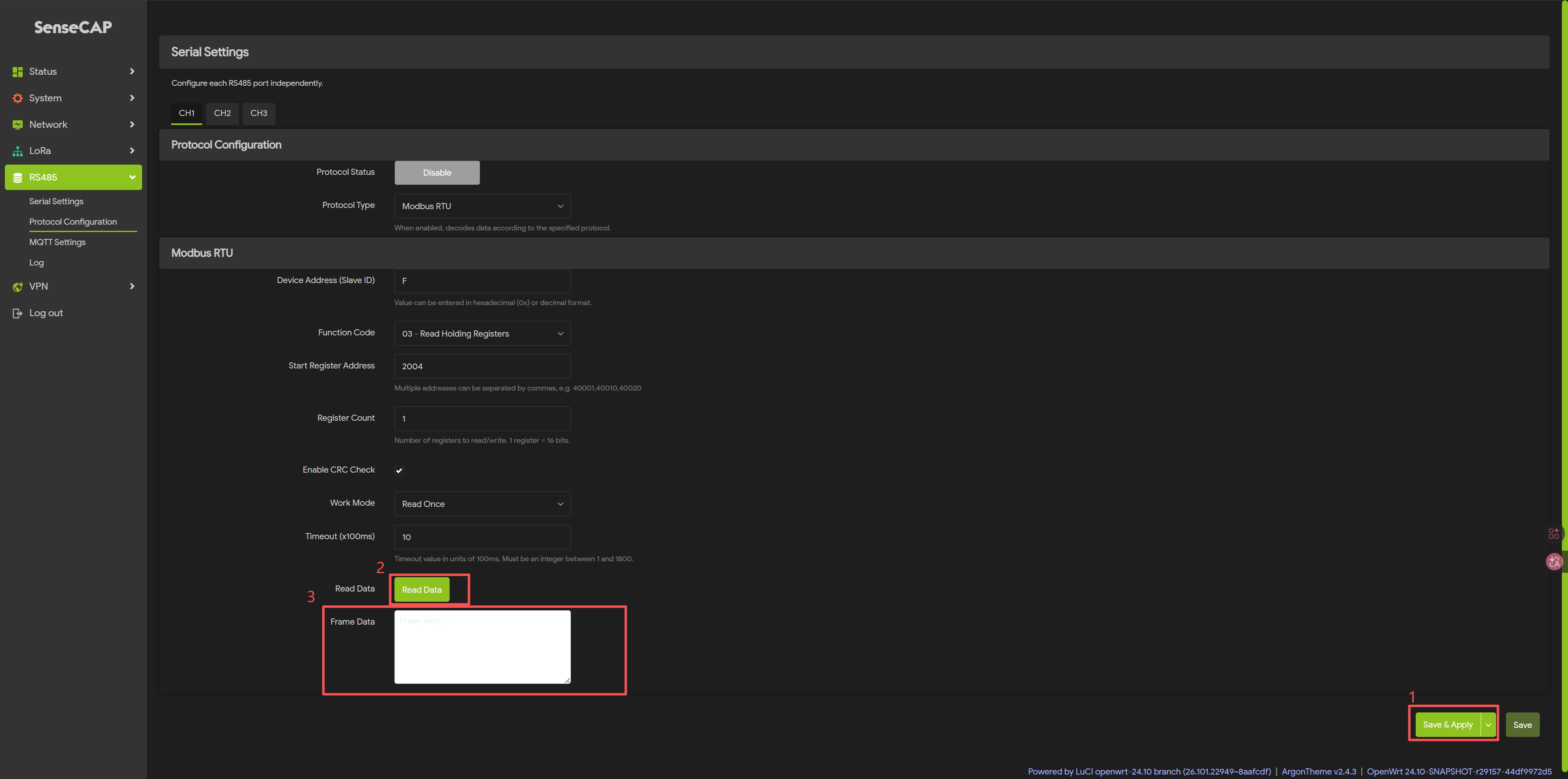
Step 5: Modbus RTU Parameter Settings
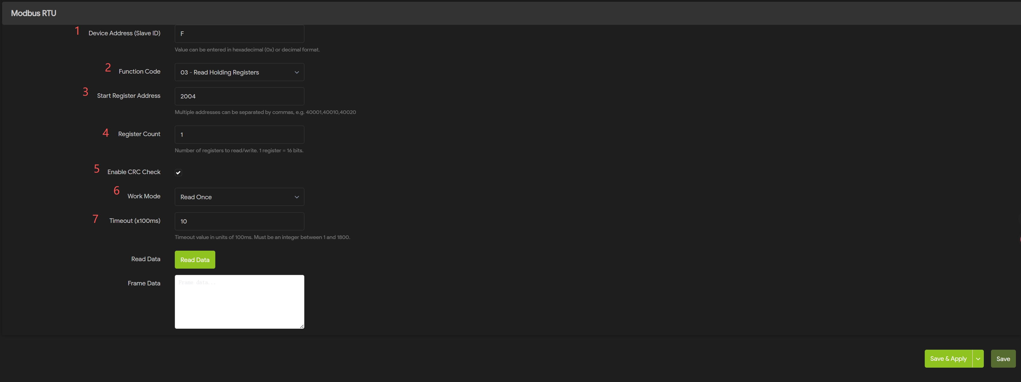
Step 6: Click onSave & Apply
Once the settings have taken effect, click the Read Data, you can see the retrieved data in the Frame Data.
Modbus TCP Parameter Configuration
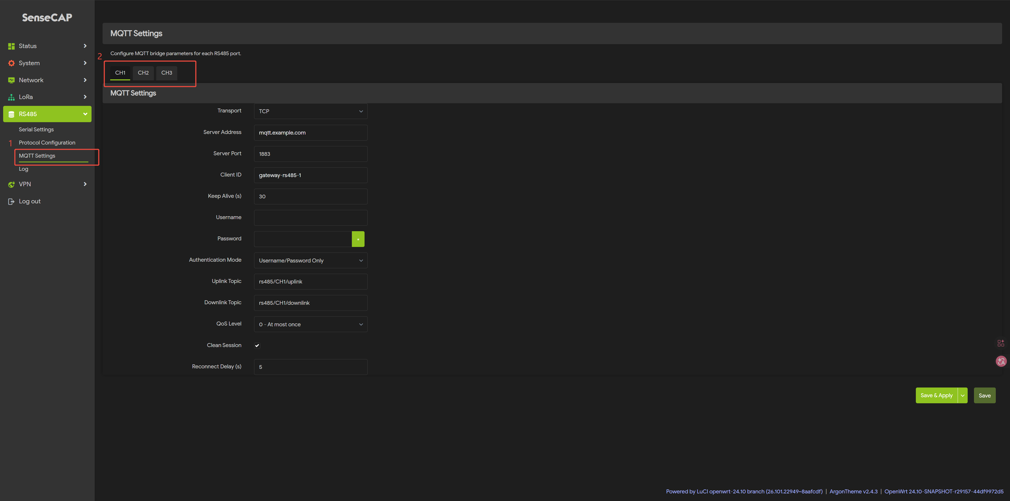
Step 7: Click on RS485 - MQTT Setttings
Select the channel you want to use (CH1, CH2, CH3).
Select TCP as the transport protocol.
Step 8: MQTT Settings
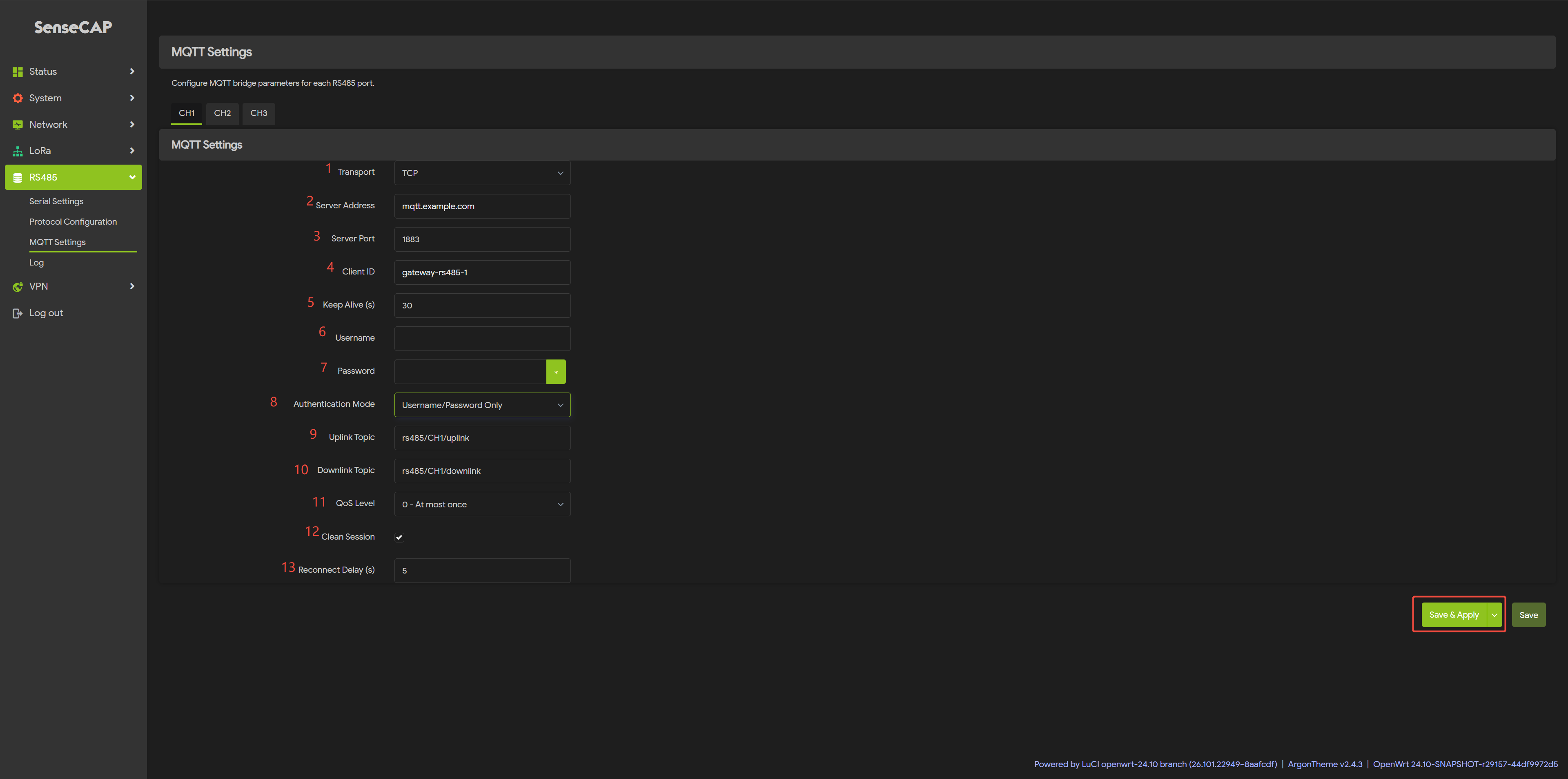
Step 9: Click onSave & Apply
Now your configuration is active.
Tech Support & Product Discussion
Thank you for choosing our products! We are here to provide you with different support to ensure that your experience with our products is as smooth as possible. We offer several communication channels to cater to different preferences and needs.