Interfaces Usage
This wiki introduces the various different hardware and interfaces on the J501 Carrier Board and how to use them to expand your project ideas.
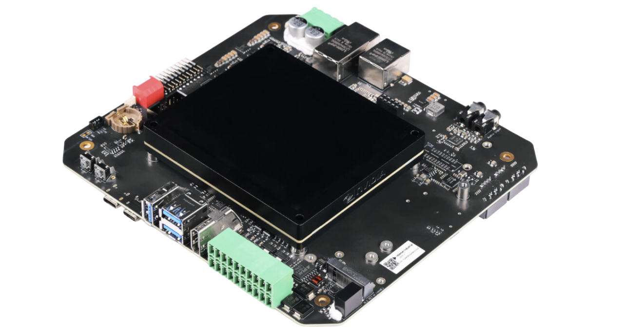
GMSL Camera
We need to combine the J501 carrier board with the GMSL expansion board to activate the GMSL functionality. The J501 GMSL Extension Board is designed for connecting up to 8 GMSL cameras with reServer Industrial J501 carrier board, which is compatible with NVIDIA® Jetson AGX Orin™. This extension board is using the deserializer 'MAX96724'.
Compatible Cameras
Hardware Connection
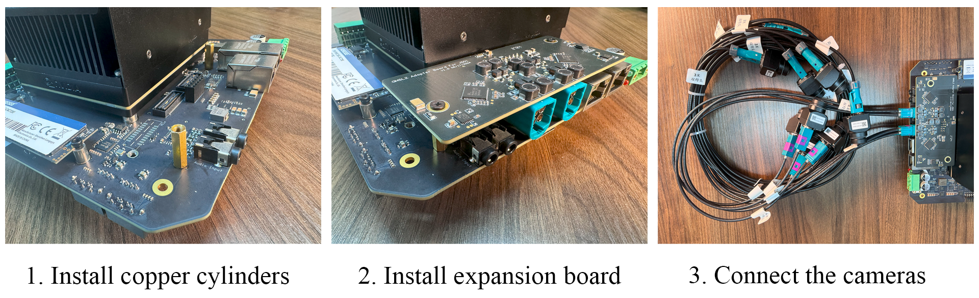
- Step1. Install copper cylinders to J501 carrier board.
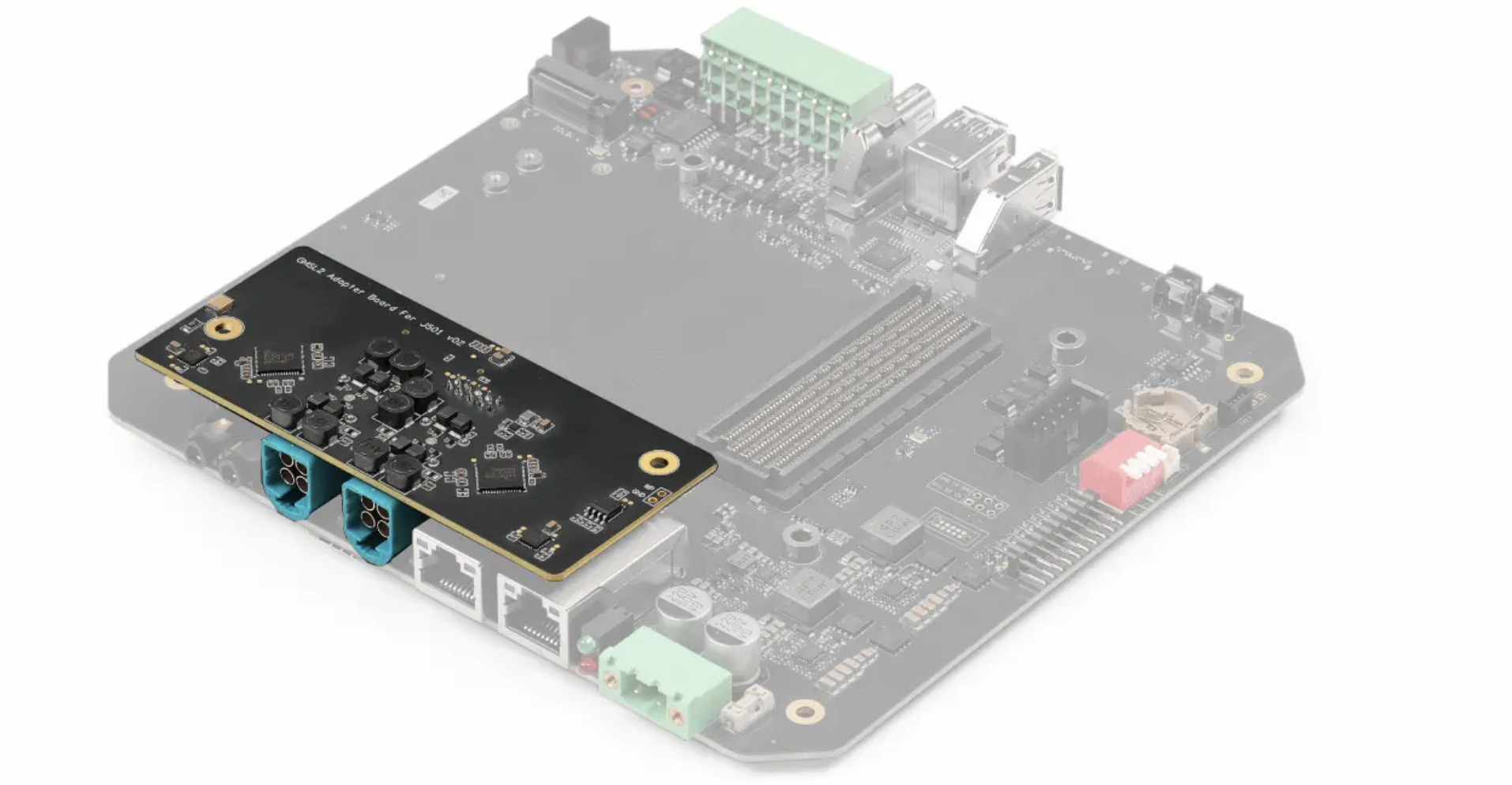
- Step2. Connect the GMSL expansion board to the J501 carrier board and secure them using screws.
- Step3. Connect the GMSL camera.
Usage Instruction
Before enabling the GMSL functionality, please ensure that you have installed a JetPack version with the GMSL expansion board driver.
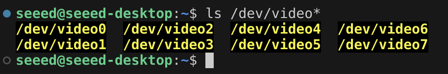
Step1. In the jetson device terminal, enter the following command to check if the connected camera is recognized correctly.
ls /dev/video*
Step2. Install the video interface configuration tools.
sudo apt install v4l-utils
Step3. Set the channel format for the serializer and deserializer.
media-ctl -d /dev/media0 --set-v4l2 '"ser_0_ch_0":1[fmt:YUYV8_1X16/1920x1536]'
media-ctl -d /dev/media0 --set-v4l2 '"ser_1_ch_1":1[fmt:YUYV8_1X16/1920x1536]'
media-ctl -d /dev/media0 --set-v4l2 '"ser_2_ch_2":1[fmt:YUYV8_1X16/1920x1536]'
media-ctl -d /dev/media0 --set-v4l2 '"ser_3_ch_3":1[fmt:YUYV8_1X16/1920x1536]'
media-ctl -d /dev/media0 --set-v4l2 '"ser_4_ch_0":1[fmt:YUYV8_1X16/1920x1536]'
media-ctl -d /dev/media0 --set-v4l2 '"ser_5_ch_1":1[fmt:YUYV8_1X16/1920x1536]'
media-ctl -d /dev/media0 --set-v4l2 '"ser_6_ch_2":1[fmt:YUYV8_1X16/1920x1536]'
media-ctl -d /dev/media0 --set-v4l2 '"ser_7_ch_3":1[fmt:YUYV8_1X16/1920x1536]'
media-ctl -d /dev/media0 --set-v4l2 '"des_0_ch_0":0[fmt:YUYV8_1X16/1920x1536]'
media-ctl -d /dev/media0 --set-v4l2 '"des_0_ch_1":0[fmt:YUYV8_1X16/1920x1536]'
media-ctl -d /dev/media0 --set-v4l2 '"des_0_ch_2":0[fmt:YUYV8_1X16/1920x1536]'
media-ctl -d /dev/media0 --set-v4l2 '"des_0_ch_3":0[fmt:YUYV8_1X16/1920x1536]'
media-ctl -d /dev/media0 --set-v4l2 '"des_1_ch_0":0[fmt:YUYV8_1X16/1920x1536]'
media-ctl -d /dev/media0 --set-v4l2 '"des_1_ch_1":0[fmt:YUYV8_1X16/1920x1536]'
media-ctl -d /dev/media0 --set-v4l2 '"des_1_ch_2":0[fmt:YUYV8_1X16/1920x1536]'
media-ctl -d /dev/media0 --set-v4l2 '"des_1_ch_3":0[fmt:YUYV8_1X16/1920x1536]'
We need to set the channel format for the serializer and deserializer every time the device restarts.
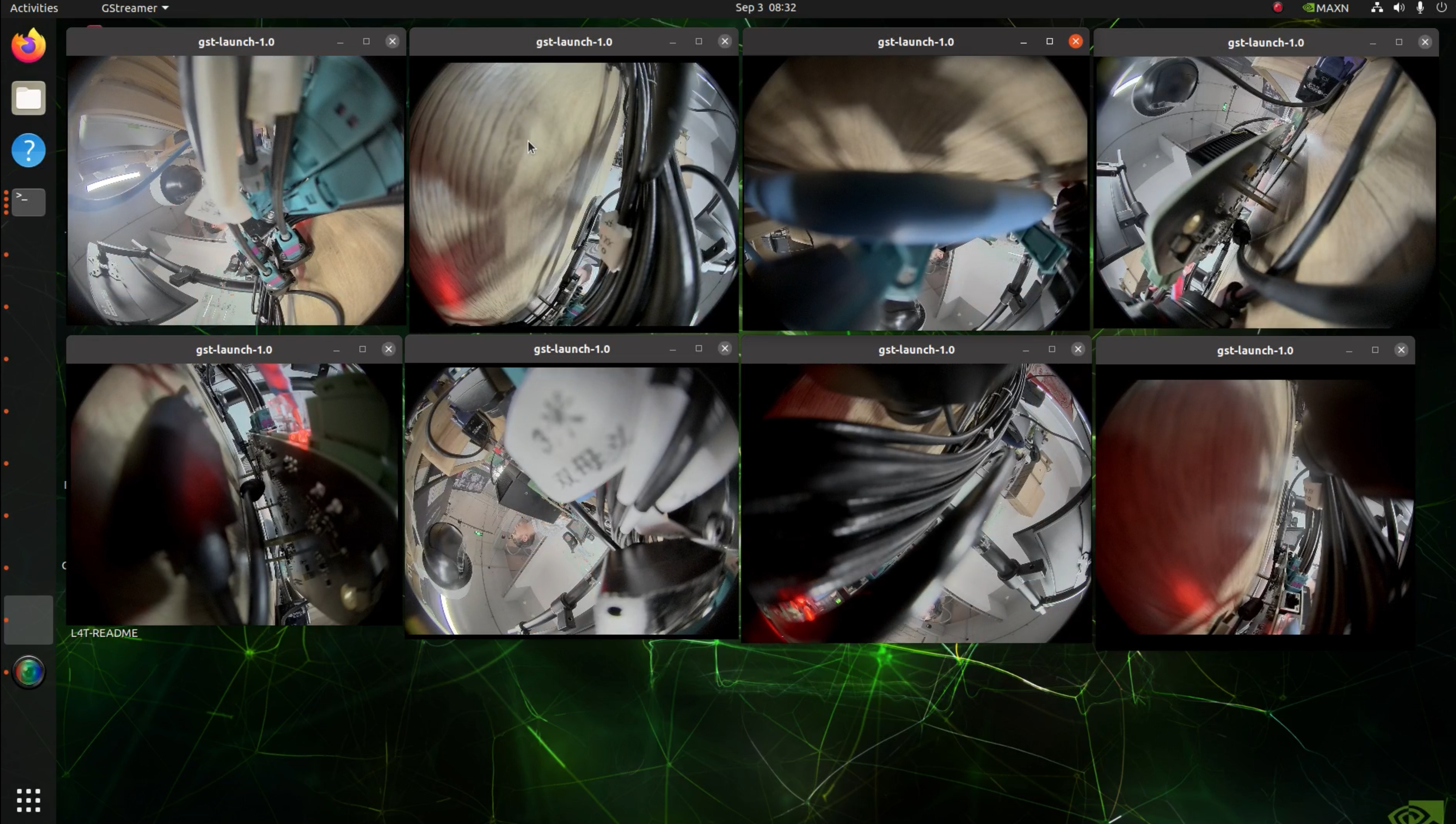
Step4. We can use the following command to quickly start the camera and open a window to display the video stream.
gst-launch-1.0 v4l2src device=/dev/video0  ! xvimagesink -ev
gst-launch-1.0 v4l2src device=/dev/video1  ! xvimagesink -ev
gst-launch-1.0 v4l2src device=/dev/video2  ! xvimagesink -ev
gst-launch-1.0 v4l2src device=/dev/video3  ! xvimagesink -ev
gst-launch-1.0 v4l2src device=/dev/video4  ! xvimagesink -ev
gst-launch-1.0 v4l2src device=/dev/video5  ! xvimagesink -ev
gst-launch-1.0 v4l2src device=/dev/video6  ! xvimagesink -ev
gst-launch-1.0 v4l2src device=/dev/video7  ! xvimagesink -ev
Gigabit Ethernet Connectors
There are 2 Ethernet ports on the J501.
- eth0: Standard Gigabit Ethernet port with 10/100/1000Mbps specification.
- eth1: 10-Gigabit Ethernet port.
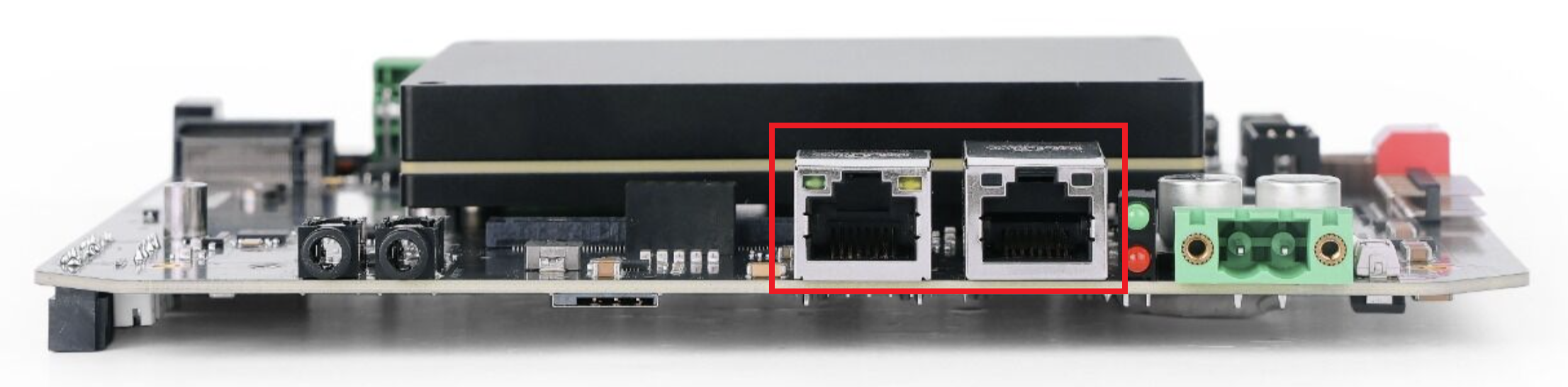
There are 2 LEDs (green and yellow) on each Ethernet port:
- Green LED: ON only when connected to 1000M/10G network.
- Yellow LED: Shows the network activity status.
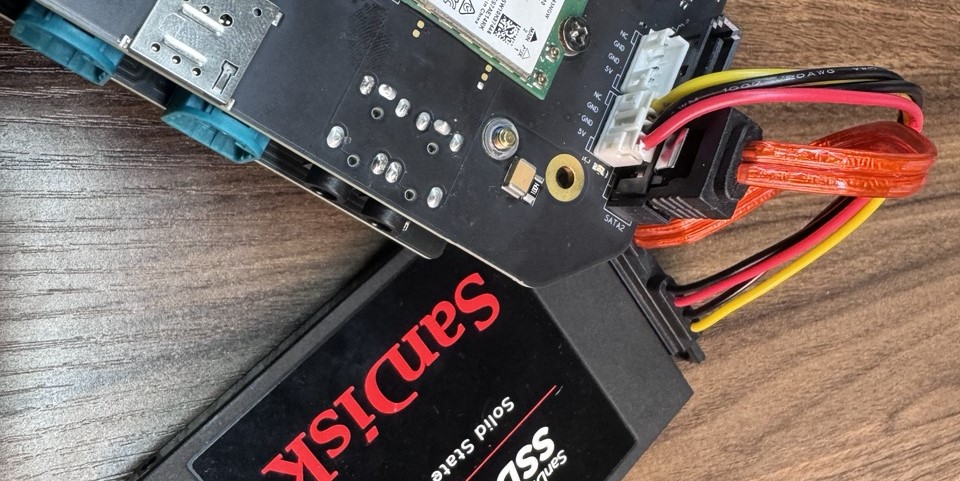
SATA Connectors
reServer J501 carrier board supports 2x SATA 2.5" HDD/SSD and comes with both SATA data and power connectors. You can connect to HDD/ SSD as follows:
Usage Instruction
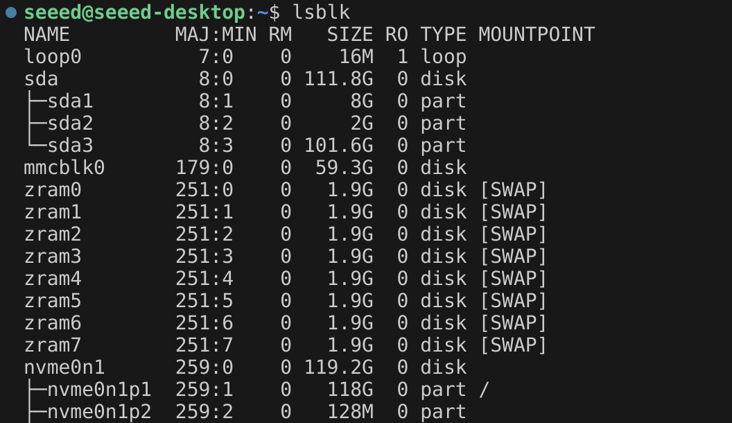
After the Jetson device system boots up, you can verify the connected SATA drives by lsblk.
M.2 Key M
M.2 Key M is an interface designed for high-speed solid-state drives (SSDs), providing ultra-fast data transfer speeds, ideal for high-performance applications.
Supported SSD are as follows
- 128GB NVMe M.2 PCle Gen3x4 2280 Internal SSD
- 256GB NVMe M.2 PCle Gen3x4 2280 Internal SSD
- 512GB NVMe M.2 PCle Gen3x4 2280 Internal SSD
- 1TB NVMe M.2 PCle Gen3x4 2280 Internal SSD
Usage Instruction
Open the terminal in Jetson device and enter the following command to test the SSD's read and write speed.
sudo dd if=/dev/zero of=tempfile bs=1M count=1024 conv=fdatasync
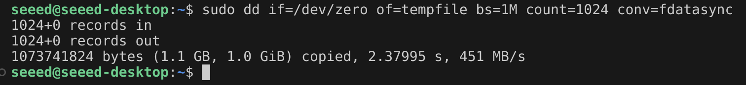
Please run sudo rm tempfile command to delete the cache files after the test is complete.
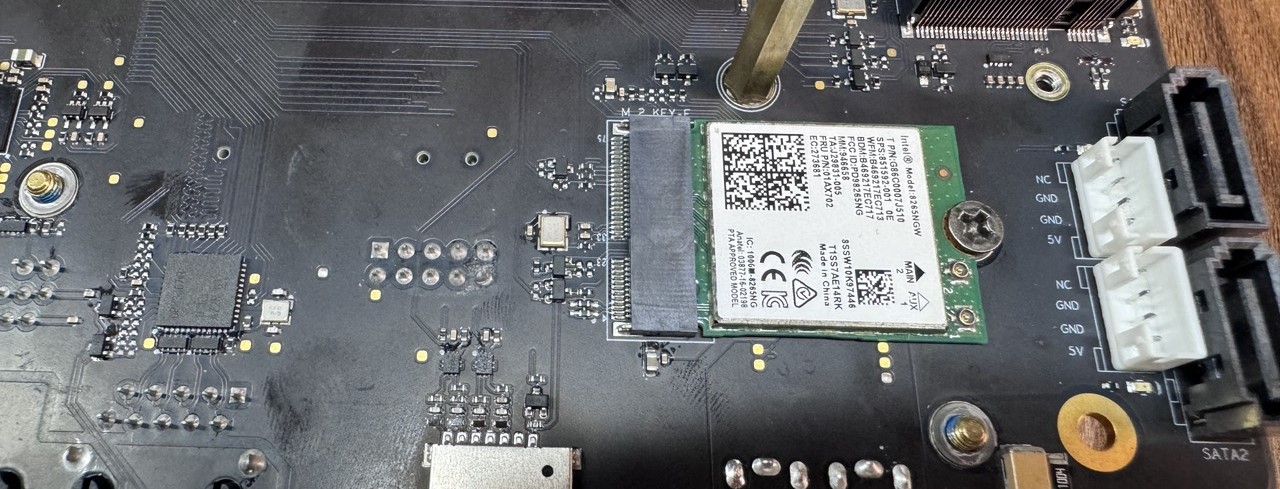
M.2 Key E
The J501 carrier board features a M.2 Key E interface, through which you can expand the device's Bluetooth and Wi-Fi capabilities.
We recommend using the Intel Dual Band Wireless-Ac 8265 w/Bluetooth 8265.NGWMG module.
Hardware Connection
Usage Instruction
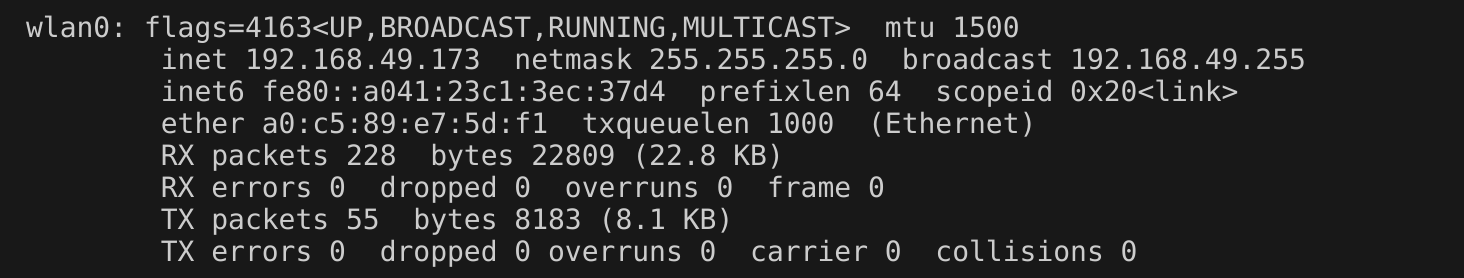
After installing the Wi-Fi module and powering on the device, we can configure the device's Wi-Fi and Bluetooth settings.
Of course, we can also check the device's operating status using the following commands.
ifconfig
bluetoothctl

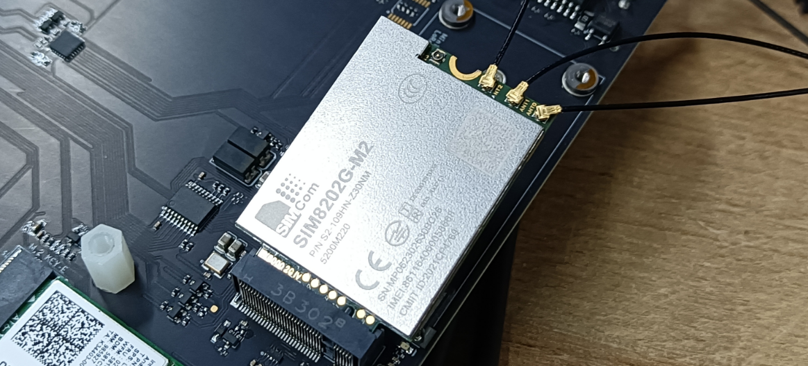
M.2 Key B
The J501 carrier board comes with a M.2 Key B connector that supports 4G and 5G modules. Currently we have tested SIM8202G-M2 5G module.
Hardware Connection
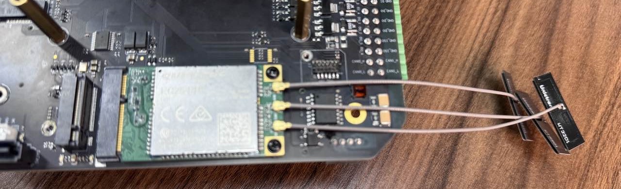
Mini PCIe
J501 carrier board comes with a mini PCIe connector that supports 4G and LoRa modules. However, you can only connect either a 4G module or a LoRa module at once. Some of the 4G modules come embedded with GPS functionality. We will discuss this as well.
4G Module
Hardware Connection
-
Step1. Add a jumper between SIM_MUX_SEL and GND pins on the 20Pin Header.
-
Step2. Slide in the 4G module to the mini PCIe slot and secure it with screws.
-
Step3. Insert a 4G-enabled nano SIM card to the SIM card slot on the board.
If you want to remove the SIM card, push the card in to hit the internal spring so that the SIM will come out of the slot
Usage Instruction
Step1. Install minicom:
sudo apt update
sudo apt install minicom -y
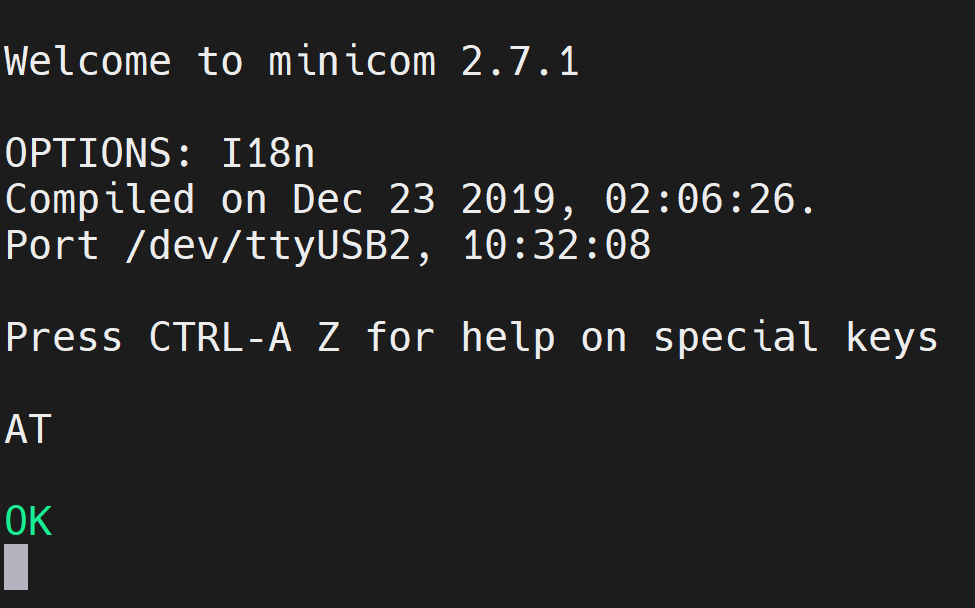
Step2. Enter the serial console of the connected 4G module so that we can enter AT commands and interact with the 4G module:
sudo minicom -D /dev/ttyUSB2 -b 115200
Step3. Press Ctrl+A and then press E to turn on local echo.
Step4. Enter the command "AT" and press enter. If you see the response as "OK", the 4G module is working properly.
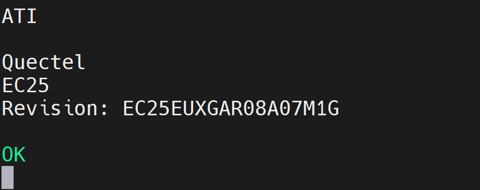
Step5. Enter the command "ATI" to check the module information.
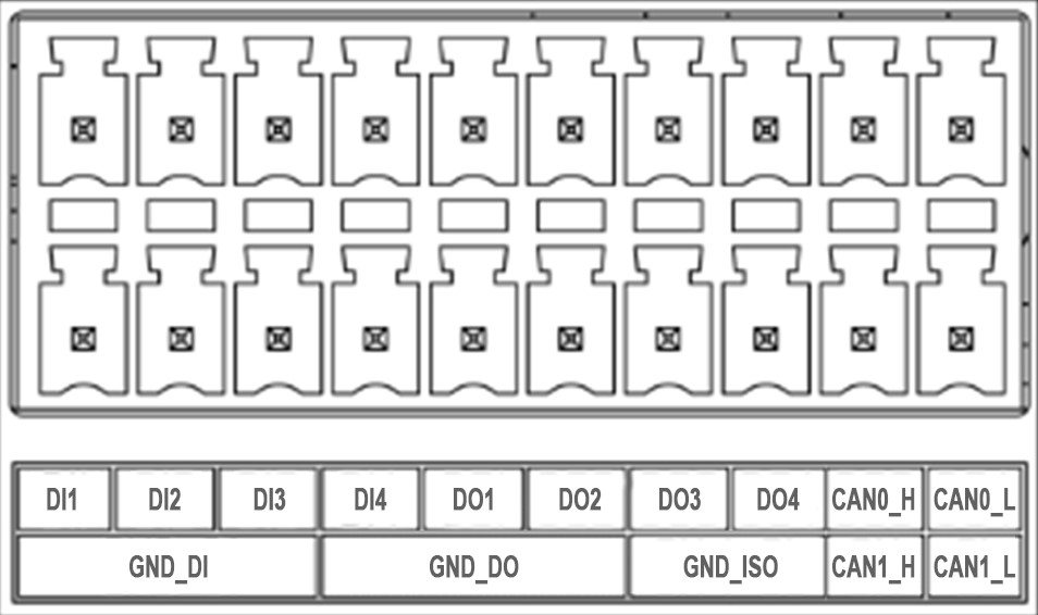
DI/DO/CAN
J501 carrier board supports 4 digital input and 4 digital output channels, all of which are optically isolated to effectively protect the mainboard from voltage spikes or other electrical disturbances. There is also two CAN interfaces on this same connector which we will discuss later in this wiki.
| Type | Label Name | Schematic Signal | Module Pin Number | BGA Number | GPIO Number | V/A Limits |
|---|---|---|---|---|---|---|
| Input | DI1 | DI_12V_1/DI_1_GPIO17 | A54 | PP.04 | 444 | 12V/ 20mA current in total |
| DI2 | DI_12V_2/DI_2_GPIO18 | C55 | PQ.04 | 452 | ||
| DI3 | DI_12V_3/DI_3_GPIO19 | K56 | PN.02 | 434 | ||
| DI4 | DI_12V_4/DI_4_GPIO33 | C54 | PM.07 | 431 | ||
| Output | DO1 | DO_40V_1/DI_1_GPIO | E59 | PAA.04 | 320 | 40V/40mA load per pin |
| DO2 | DO_40V_2/DI_2_GPIO | F59 | PAA.07 | 323 | ||
| DO3 | DO_40V_3/DI_3_GPIO | B62 | PBB.01 | 325 | ||
| DO4 | DO_40V_4/DI_4_GPIO | C61 | PBB.00 | 324 |
-
12V Digital Input, ground signal needs to be connected to GND_DI.
-
Digital output, maximum withstand voltage 40V, ground signal needs to be connected to GND_DO.
-
CAN bus with standard differential signals, ground signal needs to be connected to GND_ISO.
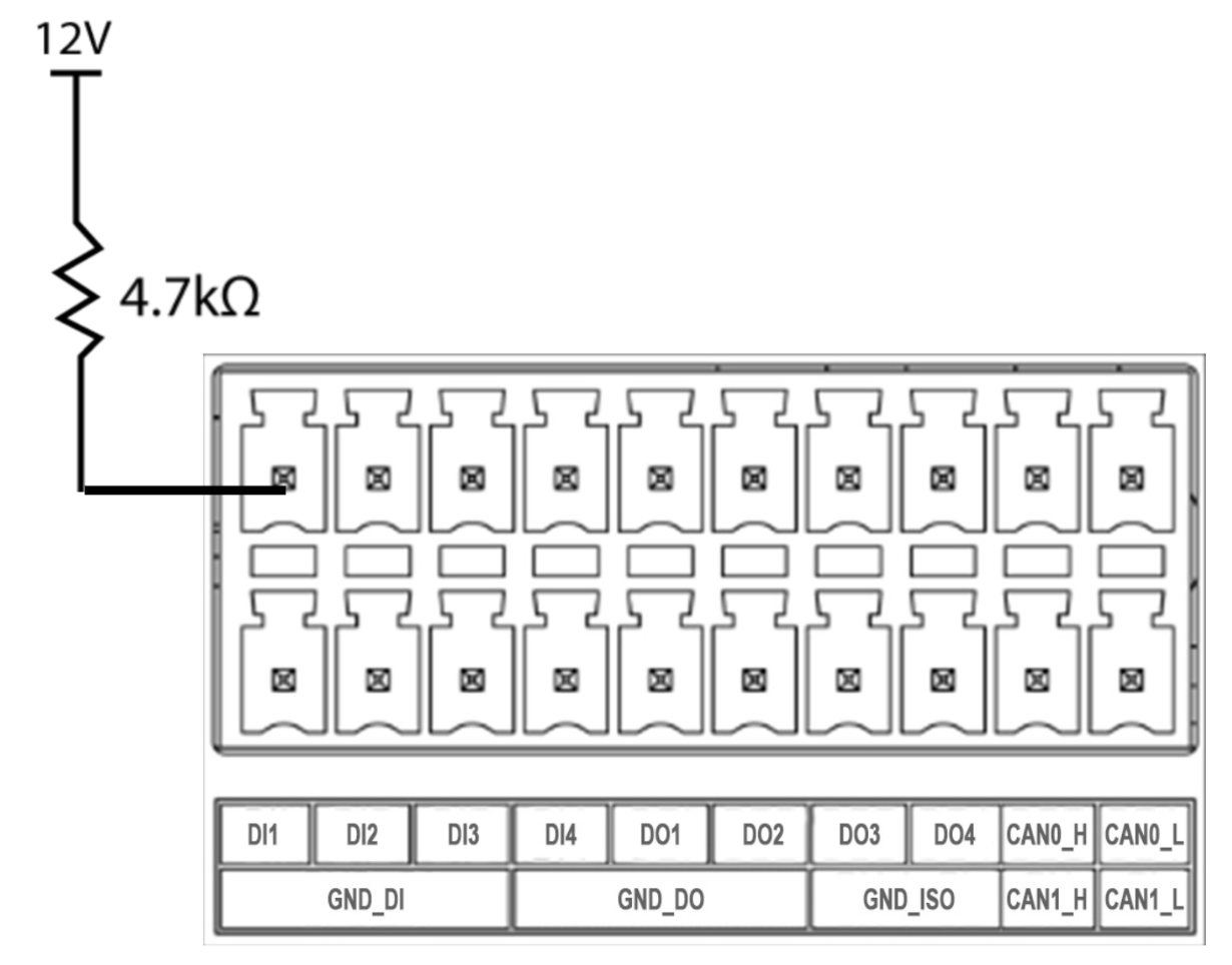
Connection Overview for DI
We can make the connection for DI by following the diagram below. It is better to add a resistor in series for the DI line. Here we have tested with a 4.7kΩ resistor connected to the DI1 pin.
Usage Instruction for DI
We need to input a voltage of 12V on the DI line in order to get detected as an input.
Step1. Make the connetions as shown above to DI1 pin and input 12V.
Step2. Open the GPIO for DI1 as follows:
sudo su
cd /sys/class/gpio
echo 444 > export
cd PP.04
We can refer the DI/DO Pin Assignment Table to find the GPIO number and BGA number. In the above example, for DI1 pin, GPIO number is 444 and BGA number is PP.04.
Step3. Execute the following to check the status:
cat value
If it outputs 0, that means there is 12V input. If it outputs 1, that means there is no input voltage.
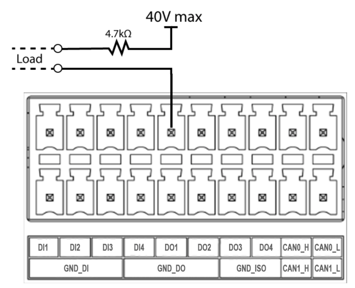
Connection Overview for DO
We can make the connection for DO by following the diagram below. It is better to add a resistor in series for the DO line. Here we have tested with a 4.7kΩ resistor.
Usage Instruction for DO
Here we need to connect a load as mentioned in the above diagram. The easiest way to test this would be to connect a multimeter if you have access to one, or else connect a load that requires less than 40V maximum voltage.
Step1. Make the connetions as shown above to DO1 pin and input 40V as max.
Step2. Open the GPIO for D01 as follows:
sudo su
cd /sys/class/gpio
echo 320 > export
cd PAA.04
echo out > direction
Step3. Execute the following to turn on the pin:
echo 1 > value
If the load is turned on or the multimeter outputs the voltage that you have input, the test it is functioning properly.
CAN
J501 carrier board features two CAN interfaces that supports the CAN FD (Controller Area Network Flexible Data-Rate) protocol at 5Mbps. The CAN interface is isolated using capacitive isolation, which provides excellent EMI protection and ensures reliable communication in industrial and automation applications. A terminal resistor of 120Ω has been installed by default and you can toggle this resistor ON and OFF using GPIO.
The CAN interface uses an isolated power supply, which means that the ground signal for external devices connected to the CAN interface should be connected to the GND_ISO pin.
Connection Overview with USB to CAN Adapter
To test and interface with CAN bus, connect a USB to CAN adapter to the CAN connectors on the board as shown below:
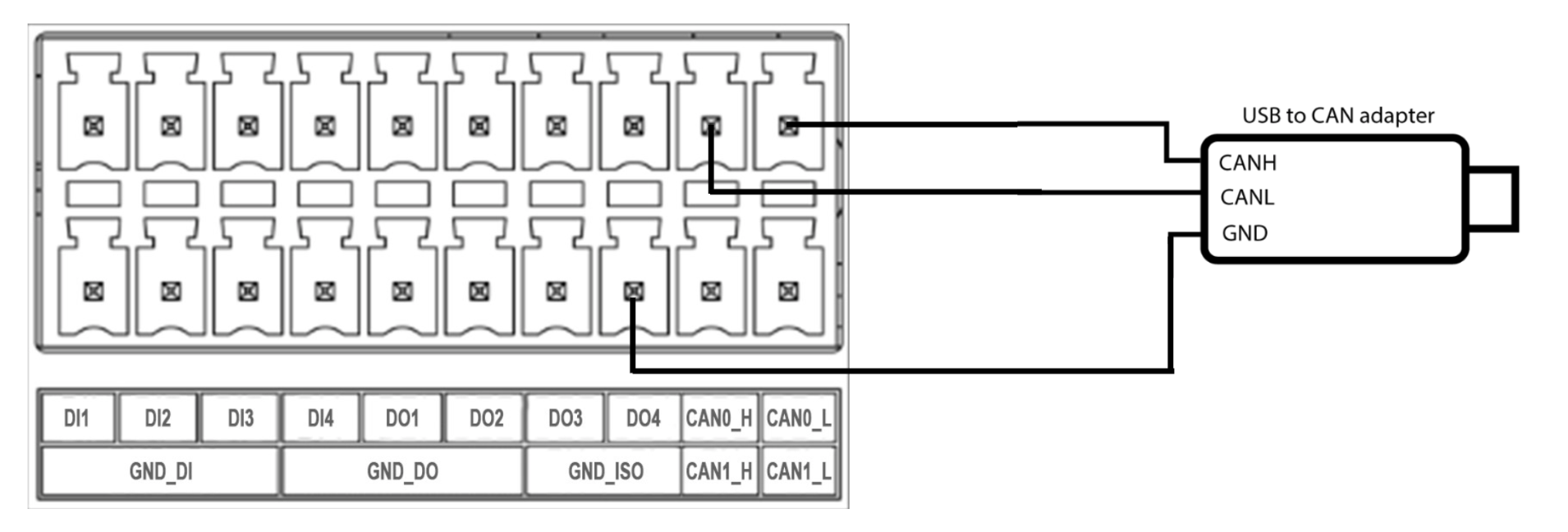
Here we have used USB to CAN Analyzer Adapter with USB Cable available on our Bazaar.
Usage Instruction with USB to CAN Adapter
Step1. Download the driver for the USB to CAN adapter you are using from the manufacturer's website and install it. In our case, according to the adapter that we used, the drivers can be found here.
Step2. Some adapters also come with the necessary software for the PC in order to communicate with the CAN device. In our case, according to the adapter that we used, we have downloaded and installed the software which can be found here.
Step3. Initialize the CAN interface of Jetson.
Create a new file named can_init.sh in Jetson and write the following content:
#!/bin/bash

sudo gpioset gpiochip2 9=0
sudo gpioset gpiochip2 8=0

sudo busybox devmem 0x0c303018 w 0xc458
sudo busybox devmem 0x0c303010 w 0xc400
sudo busybox devmem 0x0c303008 w 0xc458
sudo busybox devmem 0x0c303000 w 0xc400

sudo modprobe can
sudo modprobe can_raw
sudo modprobe mttcan

sudo ip link set can0 down
sudo ip link set can1 down

sudo ip link set can0 type can bitrate 125000
sudo ip link set can1 type can bitrate 125000
sudo ip link set can0 up
sudo ip link set can1 up
Then, run the file we just created in the Jetson terminal window:
sudo apt-get install gpiod
cd <path to can_init.sh>
sudo chmod +x can_init.sh
./can_init.sh
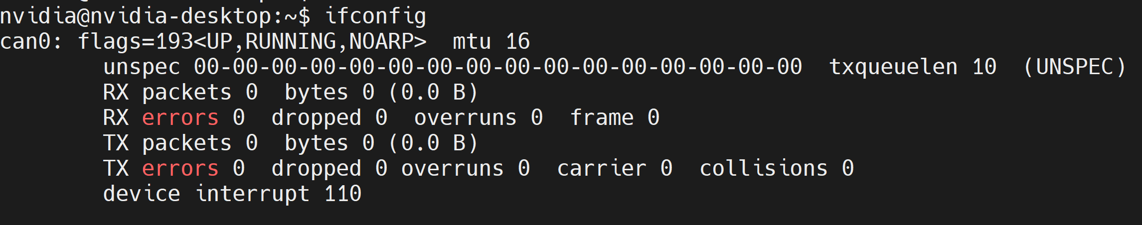
Step4. Type ifconfig on the terminal and you will see the CAN interface in enabled.
Step5. Open the CAN software that you have installed before. In this case, we will open the software that we installed according to the CAN adapter that we are using.
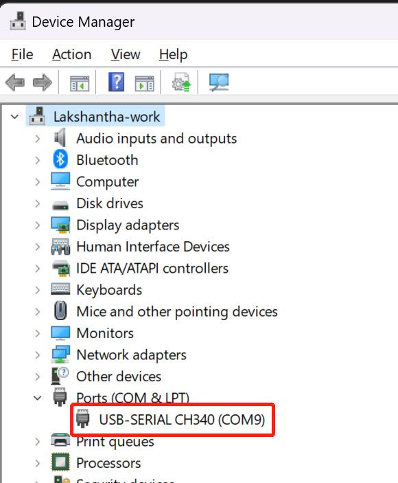
Step6. Connect the USB to CAN adapter to the PC and open Device Manager by searching it on windows search bar. Now you will see the connected adapter under Ports (COM & LPT). Make a note of the serial port listed here. According to the below image, the serial port is COM9.
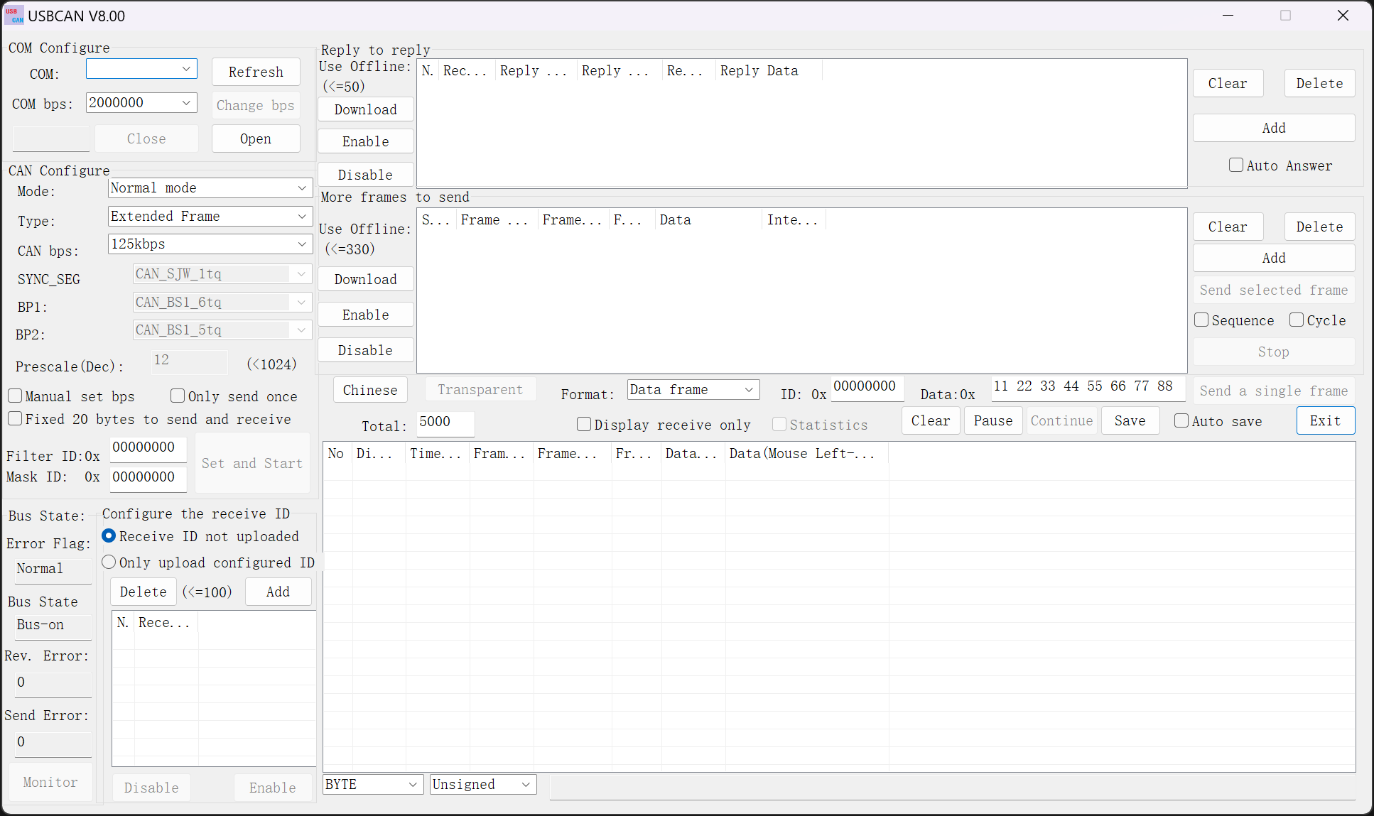
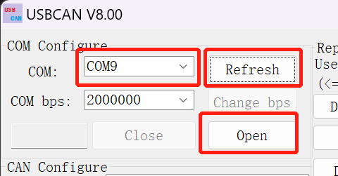
Step7. Open the CAN software, click Refresh next to COM section, click the drop-down-menu and select the serial port according to the connected adapter. Keep the COM bps at default and click Open.
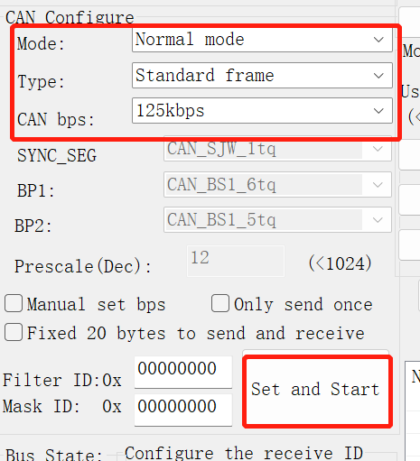
Step8. Keep the Mode and CAN bps at default, change the Type to Standard frame and click Set and Start.
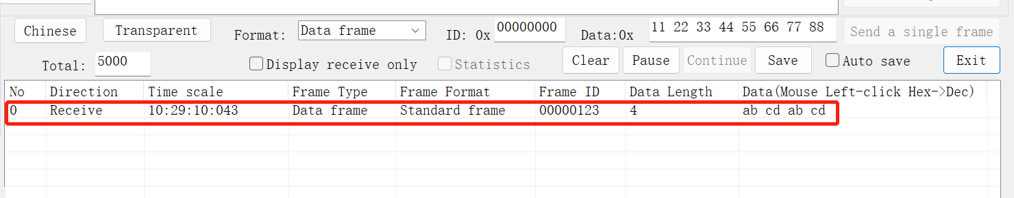
Step9. On reComputer Industrial, execute the following command to send a CAN signal to the PC:
cansend can0 123#abcdabcd
Now you will see the above signal received by the software as shown below
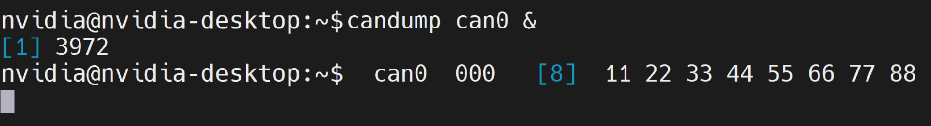
Step10. On reComputer Industrial, execute the following command to wait for receiving CAN signals from the PC:
candump can0 &
Step11. On the CAN software, click Send a single frame:
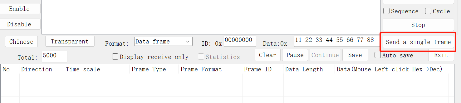
Now you will see it received by reComputer Industrial as follows:
We can also refer to here to establish communication between the J501 carrier board and the reTerminal DM via CAN.
USB
The reServer J501 carrier board has a total of 5 USB ports: 3 USB 3.1 Type-A ports, 1 USB 3.1 Type-C port, and 1 USB 2.0 Type-C port for debugging.
Usage Instruction
We can enter watch -n 1 lsusb -tv in the Jetson terminal to probe the USB ports. Once a USB device is connected, the detailed information about that port will be displayed here.
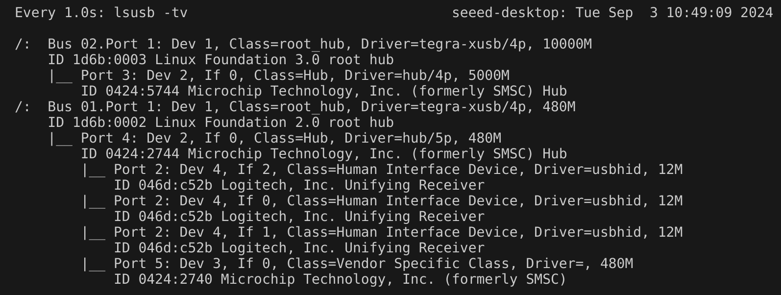
Additionally, you can refer to M.2 Key M to test the read and write speed of USB storage devices.
Please note, before testing, use the cd command to navigate to the folder where the USB storage device is mounted.
RTC
The J501 carrier board features RTC interfaces, providing accurate timekeeping even when the system is powered off.
Connection Connection
J501 carrier board is equipped with 2 different ways to connect to an RTC battery.
- RTC socket
- JST socket
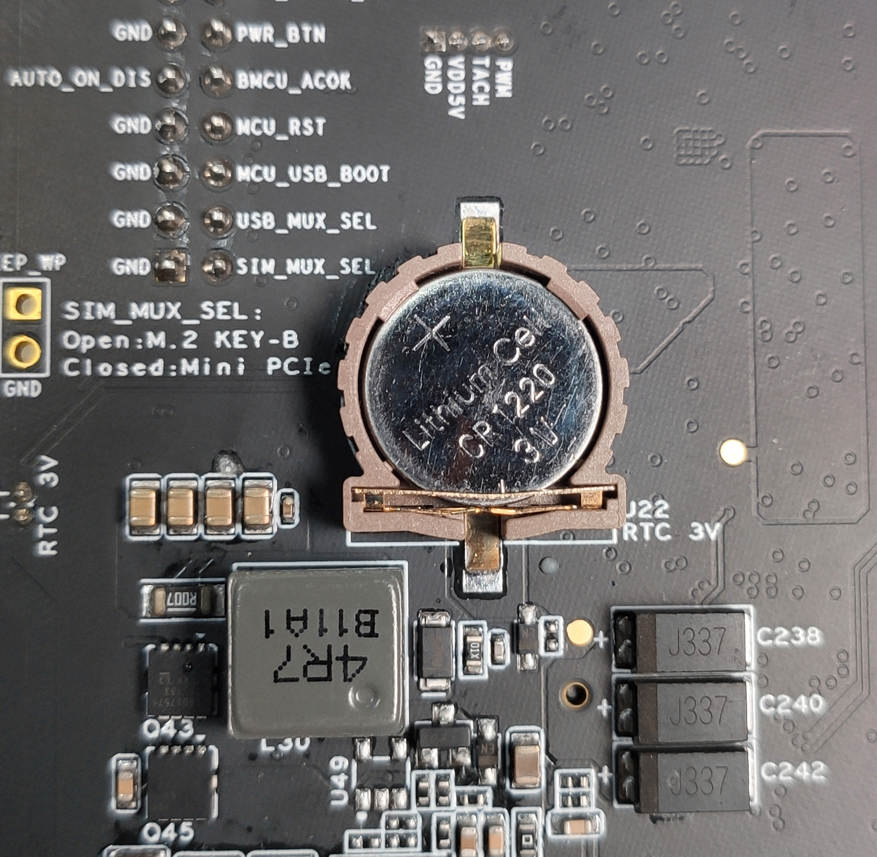
Connect a 3V CR1220 coin cell battery to the RTC socket on the board as shown below. Make sure the positive (+) end of the battery is facing upwards.
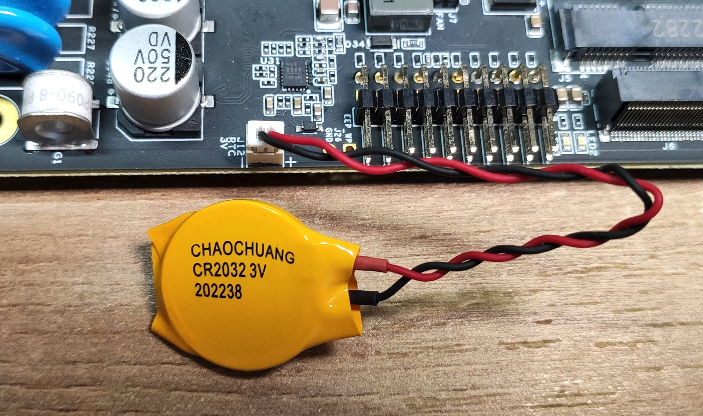
Connect a 3V CR2302 coin cell battery with JST connector to the 2-pin 1.25mm JST socket on the board as shown below
Usage Instruction
Step1. Connect an RTC battery as mentioned above.
Step2. Turn on J501.
Step3. On the Ubuntu Desktop, click the drop-down menu at the top right corner, navigate to Settings > Date & Time, connect to a network via an Ethernet cable and select Automatic Date & Time to obtain the date/ time automatically.
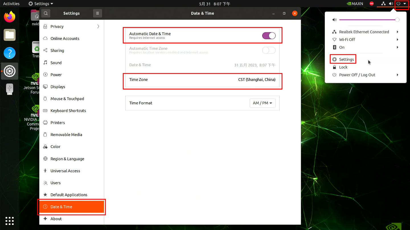
If you have not connected to internet via Ethernet, you can manually set the date/ time here.
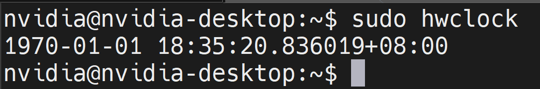
Step4. Open a terminal window, and execute the below command to check the hardware clock time:
sudo hwclock
You will see the output something like below which is not the correct date/time:
Step5. Change the hardware clock time to the current system clock time by entering the below command:
sudo hwclock --systohc
Step6. Remove any Ethernet cables connected to make sure it will not grab the time from the internet and reboot the board:
sudo reboot
Step7. Check hardware clock time to verify that the date/time stays the same eventhough the device was powered off.
Now we will create a script to always sync the system clock from the hardware clock in each boot.
Step8. Create a new shell script using any text editor of your preference. Here we use vi text editor
sudo vi /usr/bin/hwtosys.sh
Step9. Enter insert mode by pressing i, copy and paste the following content inside the file:
#!/bin/bash

sudo hwclock --hctosys
Step10. Make the script executable.
sudo chmod +x /usr/bin/hwtosys.sh
Step11. Create a systemd file:
sudo vim /lib/systemd/system/hwtosys.service
Step12. Add the following inside the file:
[Unit]
Description=Change system clock from hardware clock

[Service]
ExecStart=/usr/bin/hwtosys.sh

[Install]
WantedBy=multi-user.target
Step13. Reload systemctl daemon:
sudo systemctl daemon-reload
Step14. Enable the newly created service to start on boot and start the service:
sudo systemctl enable hwtosys.service
sudo systemctl start hwtosys.service
Step15. Verify the script is up and running as a systemd service:
sudo systemctl status hwtosys.service
Step16 Reboot the board and you will the system clock is now in sync with the hardware clock.
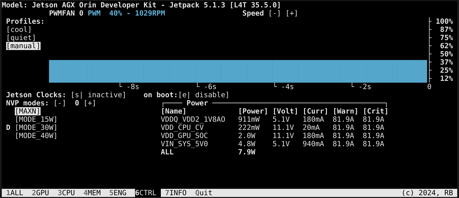
Fan
The onboard fan interface of the J501 board is managed by the nvfancontrol daemon, which adaptively adjusts the fan speed based on the operating status of the Jetson module. We can configure the working mode of the daemon through its configuration file /etc/nvfancontrol.conf.
For more information, please check here.
Additionally, we can manually set the fan speed using the jtop tool.
HDMI
J501 is equipped with an HDMI 2.1 Type A port, which supports a resolution of 7680x4320. This allows for ultra-high-definition video output.
Tech Support & Product Discussion
Thank you for choosing our products! We are here to provide you with different support to ensure that your experience with our products is as smooth as possible. We offer several communication channels to cater to different preferences and needs.