XIAO 用拡張ボードベース
概要

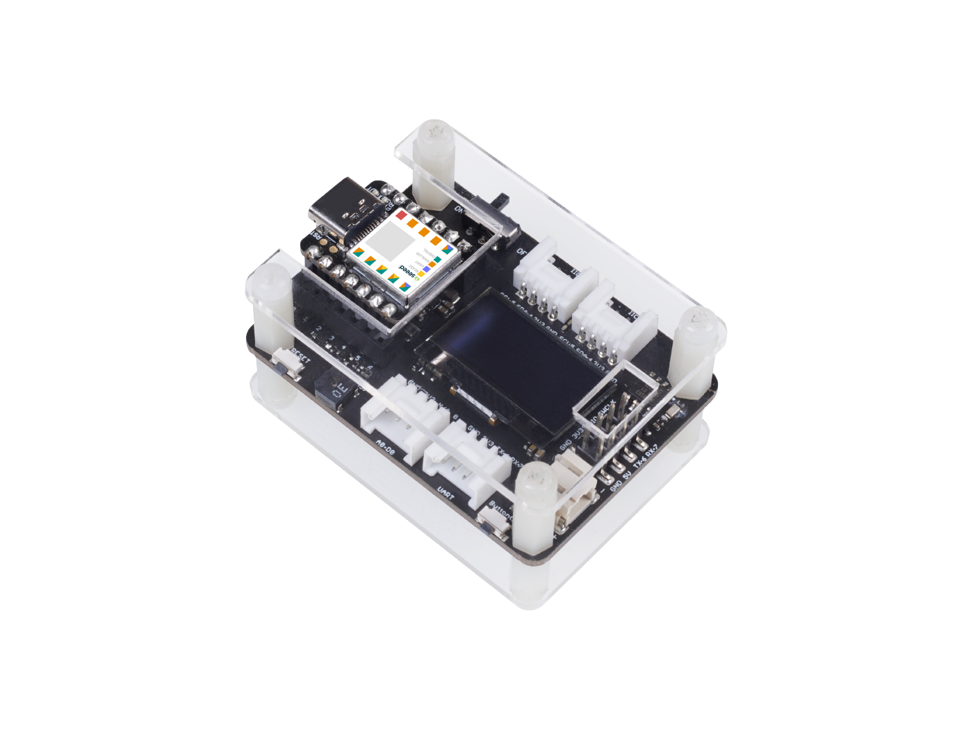
Raspberry Pi 4 の半分のサイズしかない、Seeed Studio XIAO 用の強力な機能拡張ボードです。簡単で迅速にプロトタイプやプロジェクトを構築できます。OLED、RTC、拡張可能メモリ、パッシブブザー、RESET/ユーザーボタン、5V サーボコネクタ、複数のデータインターフェースなどの豊富な周辺機器により、Seeed Studio XIAO の無限の可能性を探求できます。Circuitpython もこのボードでよくサポートされています。
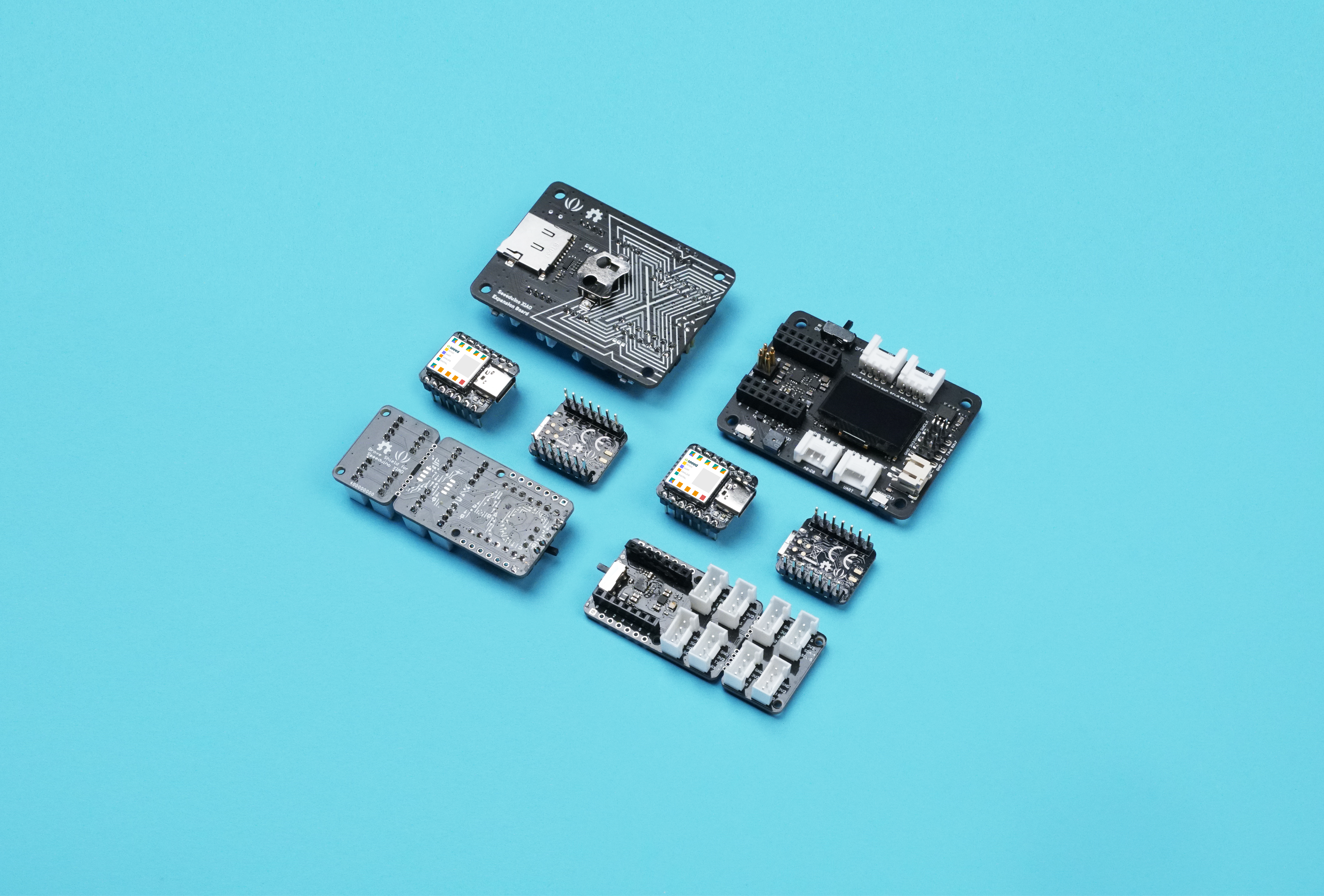
Seeed Studio XIAO フォームファクターとして、すべての Seeed Studio XIAO ボードは Grove Shield for Seeed Studio XIAO と Seeed Studio Expansion Base for XIAO の両方をサポートします。ピン間にわずかな違いがありますが、ピン配置を参照すれば簡単に管理できます。
Seeed Studio XIAO SAMD21、Seeed Studio XIAO RP2040、および Seeed Studio XIAO nRF52840 は Seeed Studio Expansion Base for XIAO と互換性があります。
特徴
- 迅速なプロトタイピング: RESET ボタンと SWD ピンがメールヘッダーに引き出されており、簡単なデバッグとリセットが可能。
- 豊富な周辺機器: OLED ディスプレイ、RTC、拡張可能メモリ空間、パッシブブザー、ユーザーボタン、オンボードバッテリー管理チップ。
- はんだ付け不要: すべてのピンが引き出されています。便利なプラグアンドプレイ Grove コネクタは、IIC、UART、アナログ/デジタルを含む複数のデータプロトコルをサポート。
- Circuit Python サポート: Circuit Python をよくサポート。MicroSD カードスロットによりメモリ空間の拡張が可能で、プロトタイピングやプロジェクト構築に必要なより多くのライブラリを割り当てることができます。
- ミニサイズ: Raspberry Pi 4 の半分のサイズでコンパクトでエレガント、特にミニサイズが必要なプロジェクトに適しています。
仕様
| 項目 | 値 |
|---|---|
| 動作電圧 | 5V / 3.7V リチウムバッテリー |
| 充電電流 | 460mA(最大) |
| RTC タイマー精度 | ± 1.5S/DAY(25°C) |
| RTC バッテリー | CR1220 |
| ディスプレイ | 0.96" OLED ディスプレイ |
| 拡張可能メモリ | MicroSD カード |
| Grove インターフェース | Grove IIC2、Grove UART1、A0/D0 Grove*1 |
| その他の外部機器 | パッシブブザー、ユーザーボタン、5V サーボコネクタ |
用途
- SWD デバッグ
- 迅速なプロトタイピング
- データ表示
- ミニサイズプロジェクト
パーツリスト
| 項目 | 値 |
|---|---|
| Seeed Studio Expansion Base for XIAO | *1 |
この製品には Seeed Studio XIAO とバッテリーは含まれていません。SWD ピンが異なるため、この拡張ボードは XIAO nRF54L15 と XIAO MG24 をサポートしていません。Seeed Studio XIAO は常に新製品を導入しています。このシリーズの最新製品開発に追いつくには、XIAO シリーズホームページをご覧ください。
入門ガイド
必要な材料
| Seeed Studio XIAO SAMD21(事前はんだ付け) | Seeed Studio Expansion Base for XIAO |
|---|---|
|
|
| 今すぐ入手 | 今すぐ入手 |

ハードウェア概要
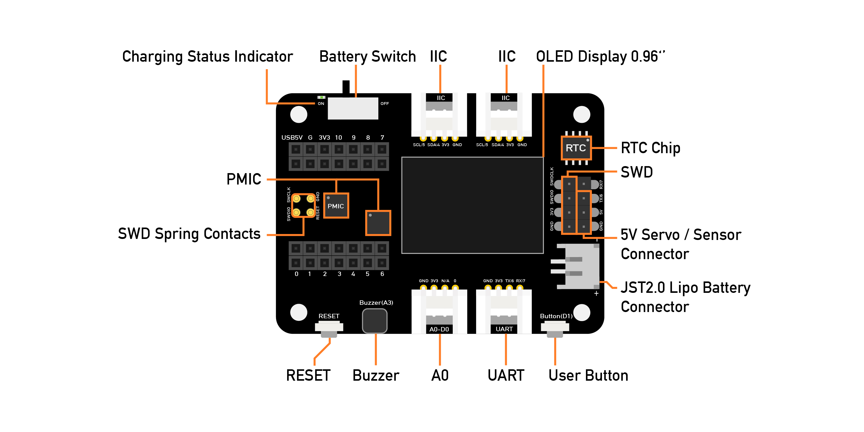
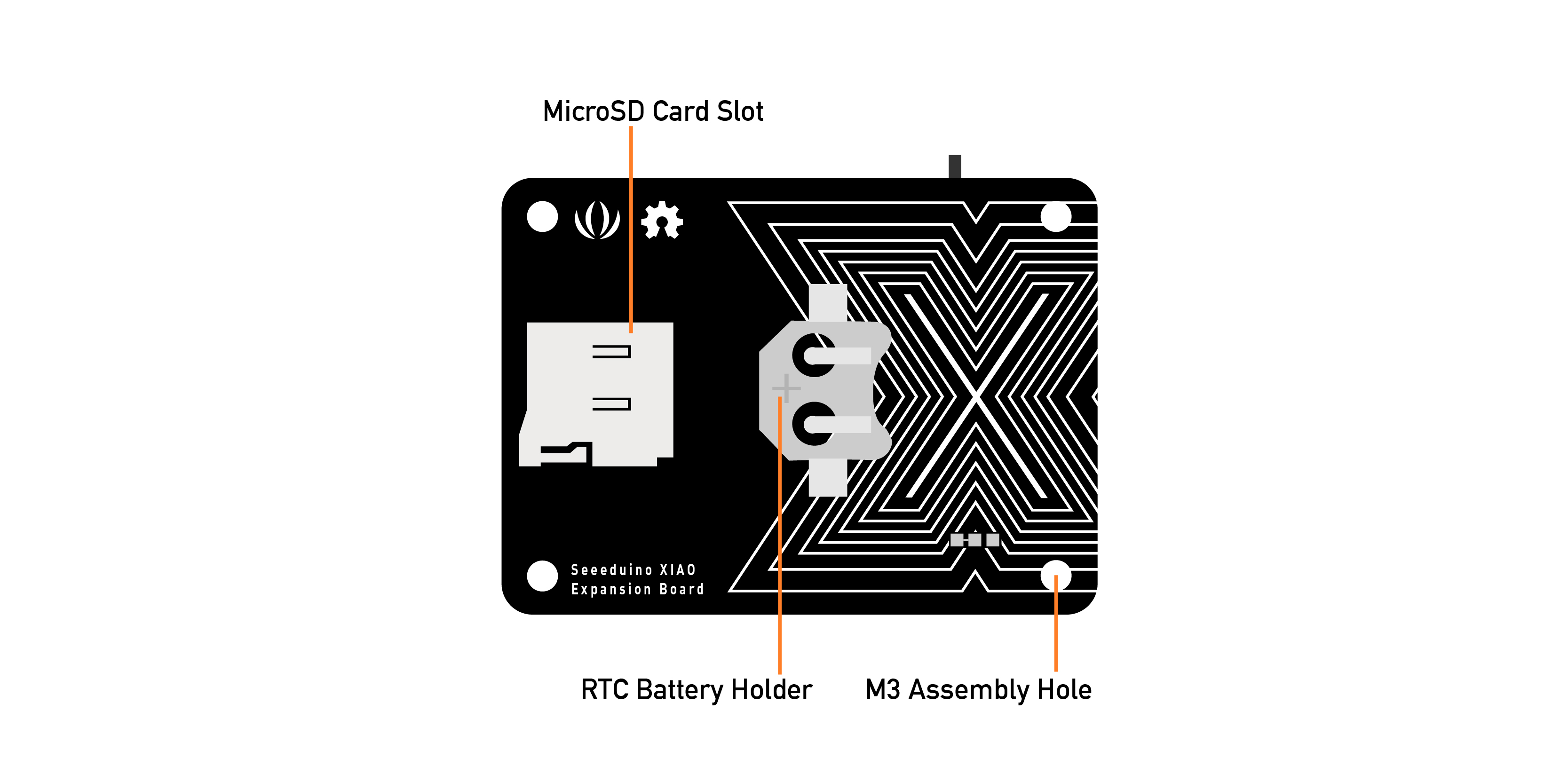
外部 MicroSD カードスロットと RTC バッテリーホルダーがあります。MicroSD カードは主に python.py ファイルの保存と実行に使用され、RTC は現在時刻を追跡し、特定の時刻にアクションをプログラムするために使用できます。
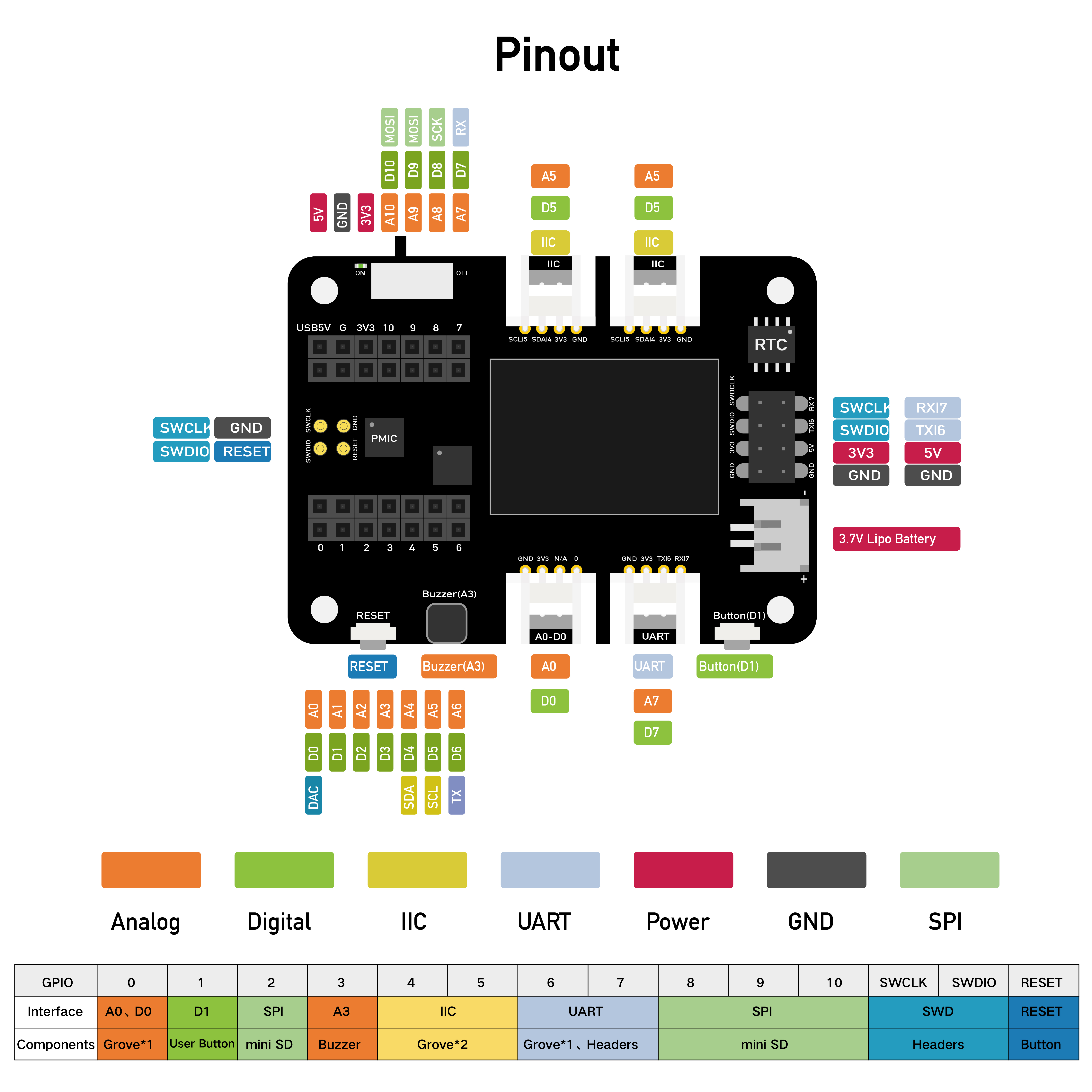
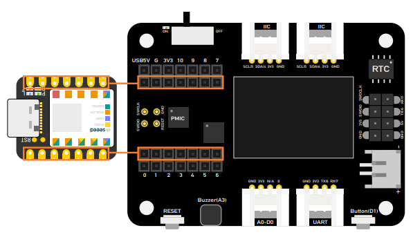
ピン配置図
Grove-Shield for Seeed Studio XIAO の外部ヘッダーピン説明。
拡張ボードの使用方法
接続
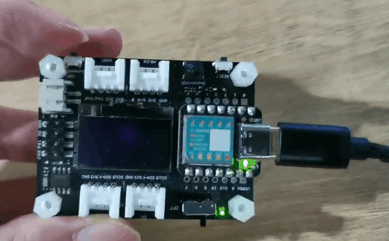
Seeed Studio XIAO SAMD21 を拡張ボードに取り付けると、Seeed Studio XIAO SAMD21 の緑色 LED が点灯するはずです。
まず Seeed Studio XIAO を拡張ボードに差し込んでから、Type-C を差し込んでください。Seeed Studio XIAO を2つのメスヘッダーコネクタの中央に差し込むことを忘れないでください。そうしないと、Seeed Studio XIAO と拡張ボードを損傷します。
バッテリーの使用
Seeed Studio Expansion Base for XIAO はバッテリーで電源供給できるため、移動が必要なデモを行う場合、そのバッテリーが電源供給の問題を解決するのに役立ちます。バッテリーを接続する際は、正極と負極に注意し、ボードを損傷しないよう写真に従ってバッテリーを接続してください。
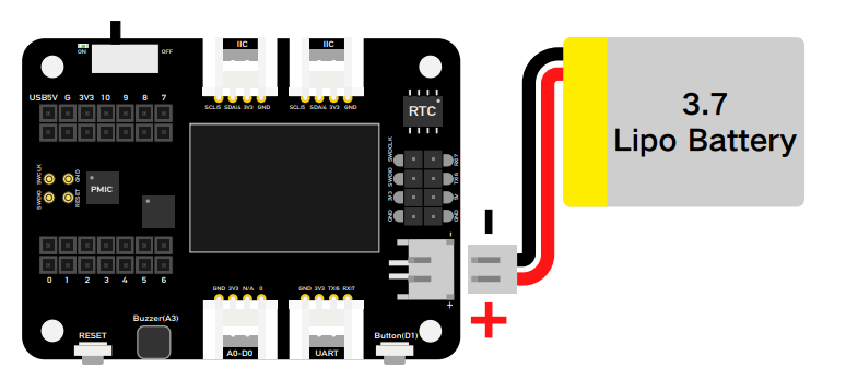
さらに、バッテリーケーブルと Type-C ケーブルを差し込み、ボタンをオンに切り替えると、ボードがバッテリーを充電します。
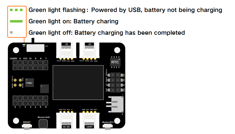
下の写真のように、LED が点滅している場合はバッテリーが充電されていないか、ボードがバッテリーに接続されていないことを意味し、LED が点灯し続けている場合はバッテリーが充電中であることを意味します。
拡張ボード上のモジュール
ボード上の豊富な周辺機器には以下が含まれます:
-
OLED ディスプレイ: PC に接続せずに視覚的なデータ表示が可能で、より効率的なデバッグを可能にし、センサーハブ、データモニターシステムなどのアプリケーションを構築できます。
-
RESET ボタン: ジャンパーワイヤーやショート回路は不要で、ワンクリックで簡単にリセットできます。
-
SWD デバッグ: SWD ピンがメールピンヘッダーとして引き出されており、デバッガー接続とファームウェアダウンロードがより簡単になります。
-
高精度 RTC: バッテリーバックアップ付きの高精度リアルタイムクロックで、メイン電源がオフになっても正確な時刻を維持できます。
-
拡張可能メモリ: 背面に MicroSD カードスロットがあり、ライブラリを追加したり Circuit Python を使用する際にメモリ制限を心配する必要がありません。
-
ユーザーボタン: RESET ボタンに加えて、もう一つのユーザー定義ボタンも提供されています。
-
パッシブブザー: PWM 周波数を変更して異なるビープ音を出し、「ブザー音楽」を作ることができます。
-
Grove コネクタ: すべてのピンが引き出され、プラグアンドプレイ Grove コネクタが一般的なデータプロトコル(Grove IIC2、Grove UART1、A0/D0 Grove*1)をサポートします。
-
Lipo バッテリー充電: JST2.0mm 標準 Lipo バッテリーコネクタとバッテリー管理システムで、USB と Lipo バッテリー電源供給の両方をサポートし、簡単なオンボードバッテリー再充電が可能です。
-
5V サーボコネクタ: 5V 出力がメールヘッダーに引き出され、5V サーボとセンサー接続用です。

OLED ディスプレイ
この例では、Seeed Studio Expansion Base for XIAO の OLED ディスプレイの使用方法を紹介します。
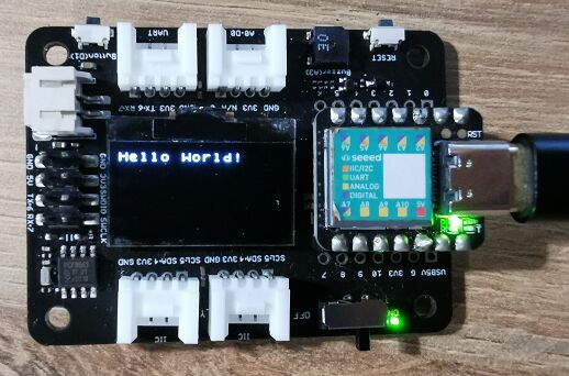
ステップ 1. Seeed Studio XIAO SAMD21 を拡張ボードに取り付けてから、Type-C ケーブルを接続します。
ステップ 2. u8g2 ライブラリをインストールします。これはライブラリのインストール方法のガイドです。
ステップ 3. コードをコピーして Arduino IDE に貼り付けてからアップロードします。
OLED コード
#include <Arduino.h>
#include <U8x8lib.h>
#include <Wire.h>

U8X8_SSD1306_128X64_NONAME_HW_I2C u8x8(/* reset=*/ U8X8_PIN_NONE, /* clock=*/ SCL, /* data=*/ SDA );   // OLEDs without Reset of the Display

void setup(void) {
  u8x8.begin();
  u8x8.setFlipMode(1);   // Enable (1) and disbale (0) 180 degree rotation of the display content
}

void loop(void) {
  u8x8.setFont(u8x8_font_chroma48medium8_r);
  u8x8.setCursor(0, 0);
  u8x8.print("Hello World!");
}
ユーザーボタンによる LED 制御
この例では、Seeed Studio Expansion Base for XIAO のボタンを使用して Seeed Studio XIAO SAMD21 の LED を制御する方法を紹介します。
ステップ 1. Seeed Studio XIAO SAMD21を拡張ボードに取り付け、Type-Cケーブルを接続します。
ステップ 2. Arduino IDEを開き、コードをコピーしてArduino IDEに貼り付け、アップロードします。
コード
const int buttonPin = 1;     // the number of the pushbutton pin
int buttonState = 0;         // variable for reading the pushbutton status

void setup() {
  // initialize the LED pin as an output:
  pinMode(LED_BUILTIN, OUTPUT);
  // initialize the pushbutton pin as an input:
  pinMode(buttonPin, INPUT_PULLUP);

}

void loop() {
  // read the state of the pushbutton value:
  buttonState = digitalRead(buttonPin);

  // check if the pushbutton is pressed. If it is, the buttonState is HIGH:
  if (buttonState == HIGH) {
    // turn LED on:
    digitalWrite(LED_BUILTIN, HIGH);
  } else {
    // turn LED off:
    digitalWrite(LED_BUILTIN, LOW);
  }

}
ブザー
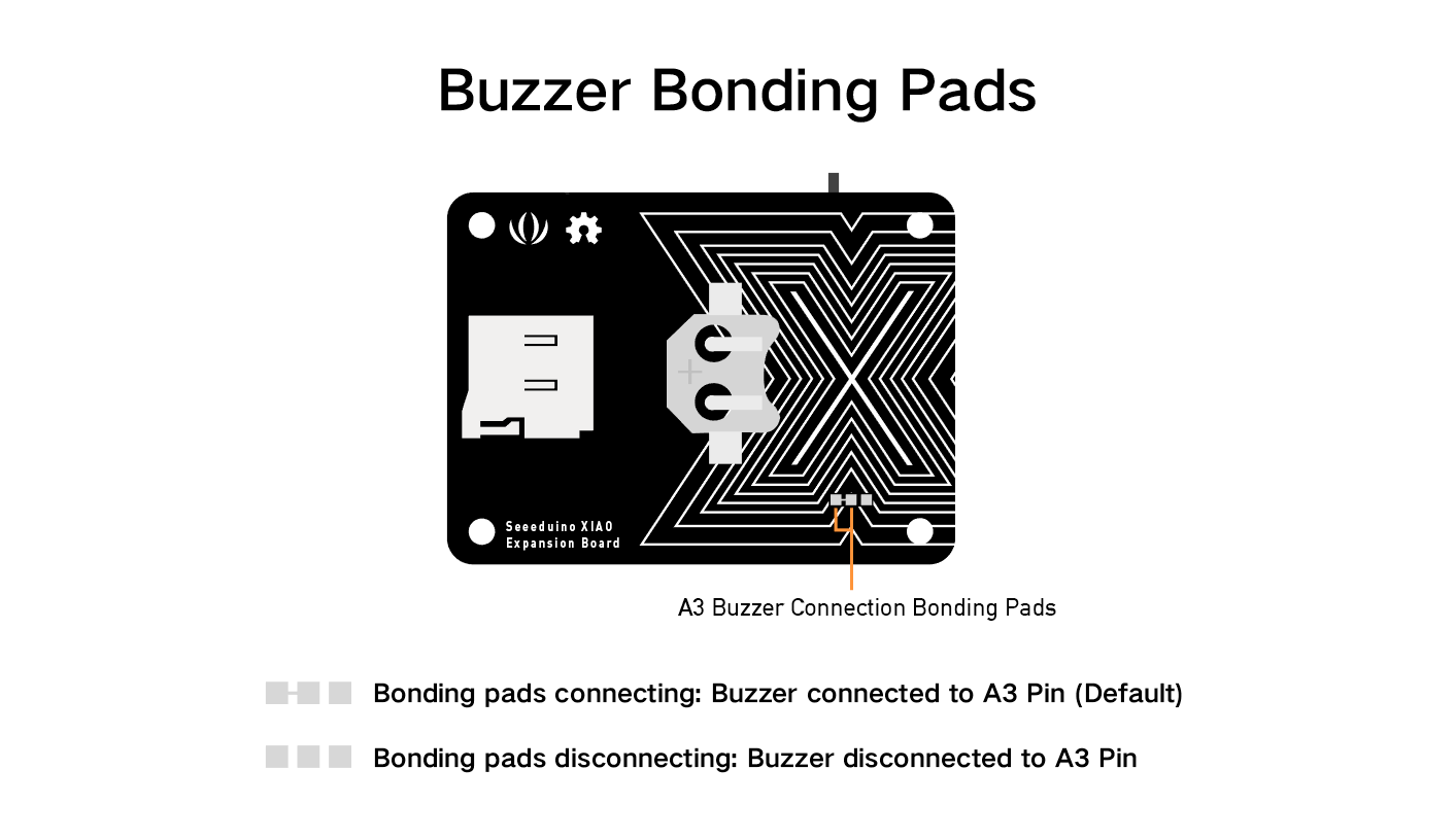
ブザーはデフォルトでピンA3に接続されています。ブザー機能を削除したい場合は、下の画像に従って線を切断してください。
パッシブブザーで楽曲を演奏
この例では、Seeed Studio Expansion Base for XIAOのブザーを使用してハッピーバースデーを演奏します。
ステップ 1. Seeed Studio XIAO SAMD21を拡張ボードに取り付け、Type-Cケーブルを接続します。
ステップ 2. Arduino IDEを開き、コードをコピーしてArduino IDEに貼り付け、アップロードします。
コード
int speakerPin = D3;
int length = 28; // the number of notes
char notes[] = "GGAGcB GGAGdc GGxecBA yyecdc";
int beats[] = { 2, 2, 8, 8, 8, 16, 1, 2, 2, 8, 8, 8, 16, 1, 2, 2, 8, 8, 8, 8, 16, 1, 2, 2, 8, 8, 8, 16 };
int tempo = 150;
void playTone(int tone, int duration) {
  for (long i = 0; i < duration * 1000L; i += tone * 2) {
    digitalWrite(speakerPin, HIGH);
    delayMicroseconds(tone);
    digitalWrite(speakerPin, LOW);
    delayMicroseconds(tone);
  }
}

void playNote(char note, int duration) {
  char names[] = {'C', 'D', 'E', 'F', 'G', 'A', 'B',
                  'c', 'd', 'e', 'f', 'g', 'a', 'b',
                  'x', 'y'
                 };
  int tones[] = { 1915, 1700, 1519, 1432, 1275, 1136, 1014,
                  956,  834,  765,  593,  468,  346,  224,
                  655 , 715
                };
  int SPEE = 5;

  // play the tone corresponding to the note name

  for (int i = 0; i < 16; i++) {
    if (names[i] == note) {
      int newduration = duration / SPEE;
      playTone(tones[i], newduration);
    }
  }
}

void setup() {
  pinMode(speakerPin, OUTPUT);
}

void loop() {
  for (int i = 0; i < length; i++) {
    if (notes[i] == ' ') {
      delay(beats[i] * tempo); // rest
    } else {
      playNote(notes[i], beats[i] * tempo);
    }
    // pause between notes
    delay(tempo);
  }
}
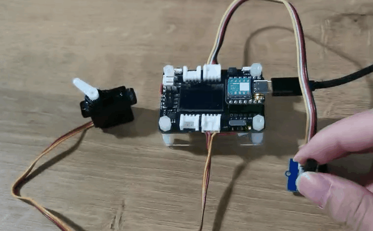
回転角度センサーによるサーボ制御
この例では、Seeed Studio Expansion Base for XIAOの統合ポートを介して、回転角度センサーを使用してサーボを制御します。
ステップ 1. Seeed Studio XIAO SAMD21を拡張ボードに取り付け、Type-Cケーブルを接続します。
ステップ 2. サーボケーブルをI2Cポートに、回転角度センサーをD0に接続します。
ステップ 3. Arduino IDEを開き、コードをコピーしてArduino IDEに貼り付け、アップロードします。
開発ボードがXIAO ESP32 シリーズの場合、以下のコードを実行する前に、まずArduino Library ManagerでESP32Servoライブラリをインストールし、以下のコードを#include <Servo.h>から#include <ESP32Servo.h>に変更する必要があります。
#include <Servo.h>
#include <Arduino.h>
#include <Wire.h>

#define ROTARY_ANGLE_SENSOR A0
#define ADC_REF 3 //reference voltage of ADC is 3v.If the Vcc switch on the seeeduino
#define GROVE_VCC 3 //VCC of the grove interface is normally 3v
#define FULL_ANGLE 300 //full value of the rotary angle is 300 degrees

Servo myservo;  // create servo object to control a servo
// twelve servo objects can be created on most boards

int pos = 0;    // variable to store the servo position

void setup() {
  Serial.begin(9600);
  pinMode(ROTARY_ANGLE_SENSOR, INPUT);
  myservo.attach(5);  // attaches the servo on pin 9 to the servo object
}

void loop() {

  float voltage;
  int sensor_value = analogRead(ROTARY_ANGLE_SENSOR);
  voltage = (float)sensor_value * ADC_REF / 1023;
  float degrees = (voltage * FULL_ANGLE) / GROVE_VCC;
  Serial.println("The angle between the mark and the starting position:");
  Serial.println(degrees);
  delay(50);
  myservo.write(degrees);
}
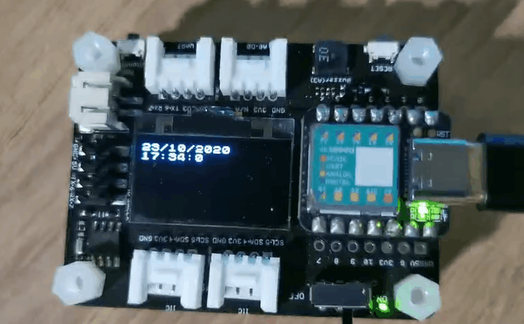
RTCクロック表示
この例では、RTCを使用してOLEDに時計を表示します。
ステップ 1. Seeed Studio XIAO SAMD21を拡張ボードに取り付け、Type-Cケーブルを接続します。
ステップ 2. u8g2とPCF8563ライブラリをインストールします。こちらがライブラリのインストール方法のガイドです。
ステップ 3. コードをコピーしてArduino IDEに貼り付け、アップロードします。
#include <Arduino.h>
#include <U8x8lib.h>
#include <PCF8563.h>
PCF8563 pcf;
#include <Wire.h>

U8X8_SSD1306_128X64_NONAME_HW_I2C u8x8(/* reset=*/ U8X8_PIN_NONE, /* clock=*/ SCL, /* data=*/ SDA );   // OLEDs without Reset of the Display

void setup() {
  Serial.begin(115200);
  u8x8.begin();
  u8x8.setFlipMode(1);
  Wire.begin();
  pcf.init();//initialize the clock
  pcf.stopClock();//stop the clock
  pcf.setYear(20);//set year
  pcf.setMonth(10);//set month
  pcf.setDay(23);//set dat
  pcf.setHour(17);//set hour
  pcf.setMinut(33);//set minut
  pcf.setSecond(0);//set second
  pcf.startClock();//start the clock
}

void loop() {
  Time nowTime = pcf.getTime();//get current time
  u8x8.setFont(u8x8_font_chroma48medium8_r);   // choose a suitable font

  u8x8.setCursor(0, 0);
  u8x8.print(nowTime.day);
  u8x8.print("/");
  u8x8.print(nowTime.month);
  u8x8.print("/");
  u8x8.print("20");
  u8x8.print(nowTime.year);
  u8x8.setCursor(0, 1);
  u8x8.print(nowTime.hour);
  u8x8.print(":");
  u8x8.print(nowTime.minute);
  u8x8.print(":");
  u8x8.println(nowTime.second);
  delay(1000);
}
SDカード機能
XIAO SAMD21、XIAO RP2040、XIAO ESP32C3、XIAO ESP32S3については、サードパーティの別のSDカードライブラリをインストールする必要はありません。以下の手順はこれらのXIAOに適用されます。
拡張ボードの回路は、SDカードスロットのCSピンがXIAOのD2ピンに接続されるように設計されています。
#include <SPI.h>
#include <SD.h>
#include "FS.h"

File myFile;

void setup() {
  // Open serial communications and wait for port to open:
  Serial.begin(115200);
  while(!Serial);              // Execute after turning on the serial monitor
  delay(500);

  Serial.print("Initializing SD card...");

  pinMode(D2, OUTPUT);          // Modify the pins here to fit the CS pins of the SD card you are using.
  if (!SD.begin(D2)) {
    Serial.println("initialization failed!");
    return;
  }
  Serial.println("initialization done.");

  // open the file. note that only one file can be open at a time,
  // so you have to close this one before opening another.
  myFile = SD.open("/test.txt", FILE_WRITE);          // The path to read and write files needs to start with "/"

  // if the file opened okay, write to it:
  if (myFile) {
    Serial.print("Writing to test.txt...");
    myFile.println("testing 1, 2, 3.");
    // close the file:
    myFile.close();
    Serial.println("done.");
  } else {
    // if the file didn't open, print an error:
    Serial.println("error opening test.txt");
  }

  // re-open the file for reading:
  myFile = SD.open("/test.txt");                       // The path to read and write files needs to start with "/"
  if (myFile) {
    Serial.println("test.txt:");

    // read from the file until there's nothing else in it:
    while (myFile.available()) {
      Serial.write(myFile.read());
    }
    // close the file:
    myFile.close();
  } else {
    // if the file didn't open, print an error:
    Serial.println("error opening test.txt");
  }
}

void loop() {
  // nothing happens after setup
}
XIAO nRF52840シリーズを使用している場合は、SDカード機能を使用するためにSdFatライブラリを別途ダウンロードする必要がある場合があります。
#include <SPI.h>
#include "SdFat.h"
SdFat SD;

#define SD_CS_PIN D2
File myFile;

void setup() {
  // Open serial communications and wait for port to open:
  Serial.begin(9600);
  while (!Serial) {
    ; // wait for serial port to connect. Needed for native USB port only
  }


  Serial.print("Initializing SD card...");

  if (!SD.begin(SD_CS_PIN)) {
    Serial.println("initialization failed!");
    return;
  }
  Serial.println("initialization done.");

  // open the file. note that only one file can be open at a time,
  // so you have to close this one before opening another.
  myFile = SD.open("/test.txt", FILE_WRITE);

  // if the file opened okay, write to it:
  if (myFile) {
    Serial.print("Writing to test.txt...");
    myFile.println("testing 1, 2, 3.");
    // close the file:
    myFile.close();
    Serial.println("done.");
  } else {
    // if the file didn't open, print an error:
    Serial.println("error opening test.txt");
  }

  // re-open the file for reading:
  myFile = SD.open("test.txt");
  if (myFile) {
    Serial.println("test.txt:");

    // read from the file until there's nothing else in it:
    while (myFile.available()) {
      Serial.write(myFile.read());
    }
    // close the file:
    myFile.close();
  } else {
    // if the file didn't open, print an error:
    Serial.println("error opening test.txt");
  }
}

void loop() {
  // nothing happens after setup
}
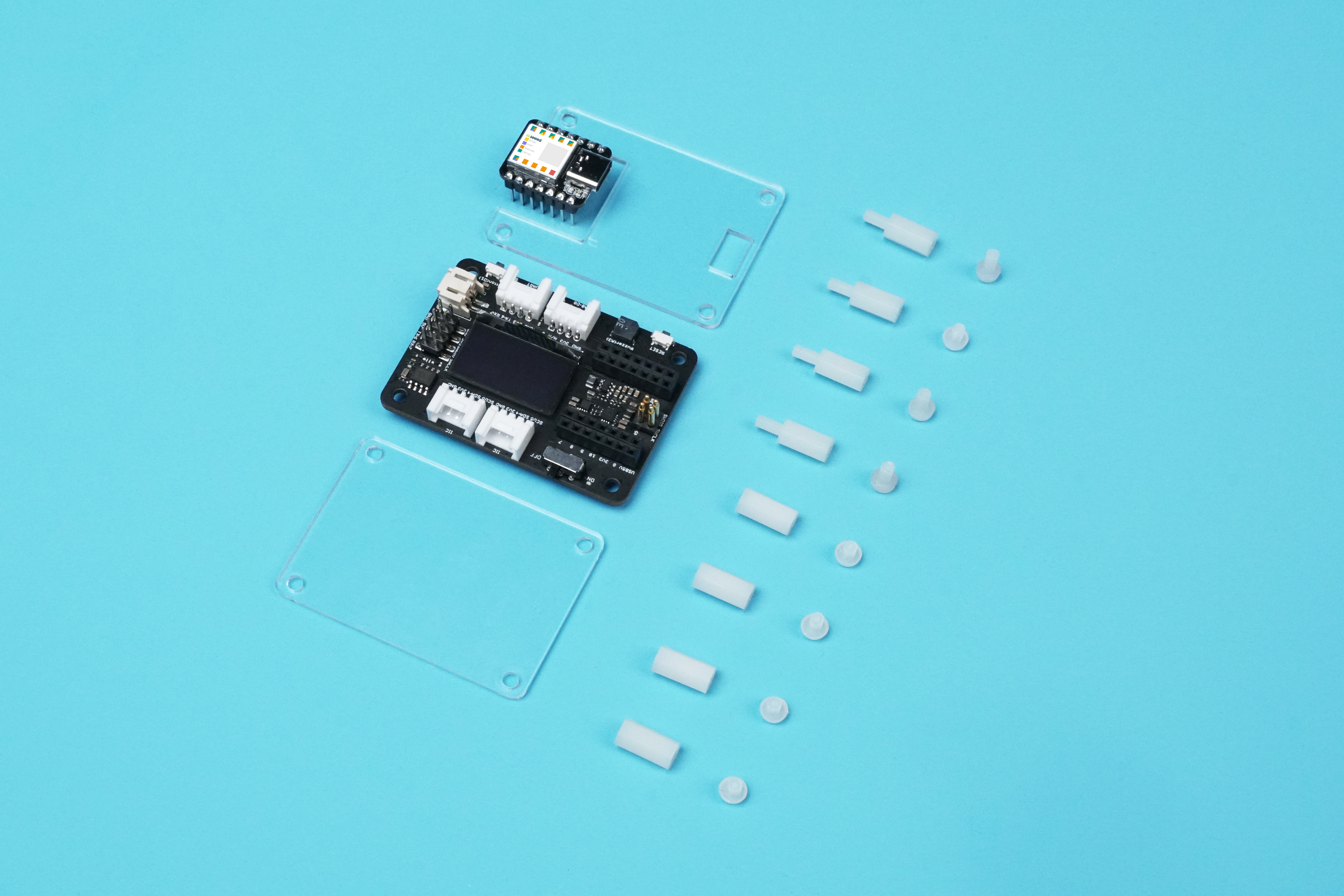
Seeed Studio XIAO 用 Seeed Studio 拡張ベースのアクリルケース

Seeed Studio XIAO 用拡張ベースを保護するために、このアクリルケースを作りました。これらはアクリルケースのコンポーネントです。
Seeed Studio XIAO 用 Grove シールドと比較して、Seeed Studio XIAO 用拡張ベースはユーザーにとって多くの便利なモジュールを追加しました。
このアクリルケースは組み立てが簡単で、ケースの見た目をより整然とさせることもできます。

拡張ボード付き Seeed Studio XIAO SAMD21 での CircuitPython
このwikiでは、Seeed Studio XIAO SAMD21 開発ボードにAdafruit Industries公式のCircuitPythonをインストールして実行する方法を紹介します!
CircuitPythonは、低コストのマイコンボードでの実験やプログラミング学習を簡素化するために設計されたプログラミング言語です。事前のデスクトップダウンロードが不要で、これまで以上に簡単に始められます。ボードをセットアップしたら、任意のテキストエディタを開いてコードの編集を開始できます。詳細については、こちらを参照してください。
CircuitPython のインストール
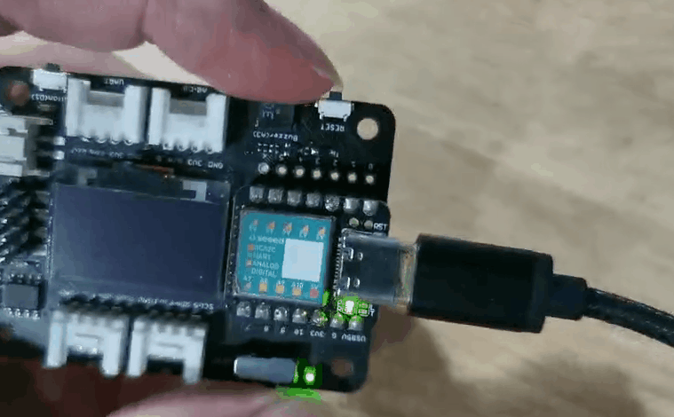
ステップ 1. Seeed Studio XIAO SAMD21 を拡張ボードにインストールし、Type-C ケーブルを接続します。
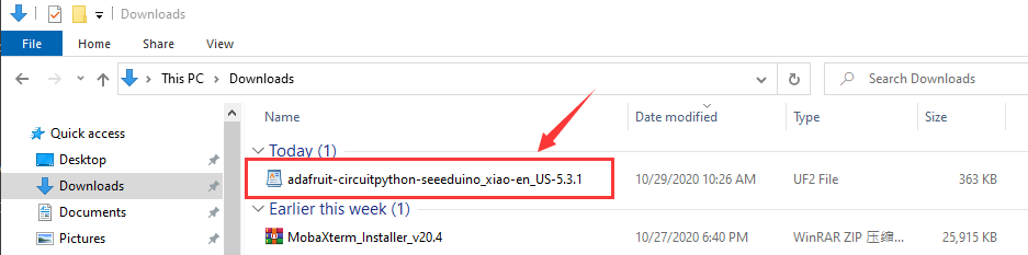
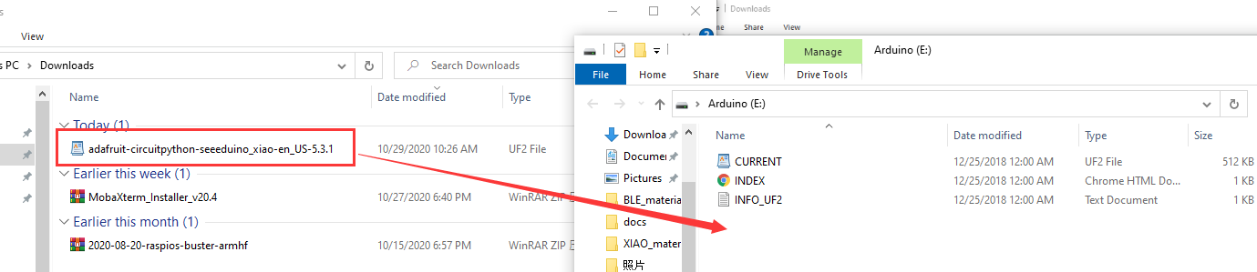
ステップ 2. 公式のSeeed Studio XIAO SAMD21 用 CircuitPython ブートローダーをダウンロードします。.uf2ファイルがPCのダウンロードフォルダに保存されます。
ステップ 3. Seeed Studio XIAO 用拡張ベースのリセットボタンを素早く2回押してDFUブートローダーモードに入ると、PCにArduinoドライブが表示されます。
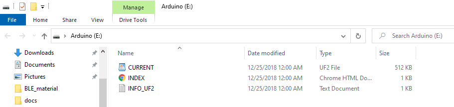
ステップ 4. PCにArduinoという名前の外部ドライブが表示されます。ダウンロードしたCircuitPython uf2ファイルをArduinoドライブにドラッグします。
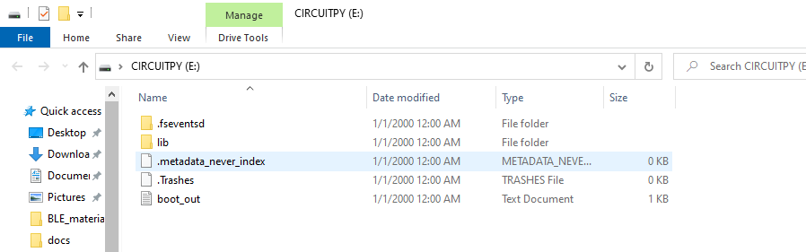
ステップ 5. CircuitPythonブートローダーがロードされたら、USB Type-Cを抜いて再接続します。CIRCUITPYという新しい外部ドライブが表示されます。
ステップ 6. これで、CircuitPythonがSeeed Studio XIAO SAMD21にロードされました!あとはPythonプログラムを書いてmain.pyという名前にし、CIRCUITPYドライブにドラッグするだけです。
CircuitPython Blink サンプル
Seeed Studio XIAOでCircuitPythonを使用する方法を紹介する簡単なサンプルです。
ステップ 1 CIRCUITPYドライブにmainという名前のtxtファイルを作成します。
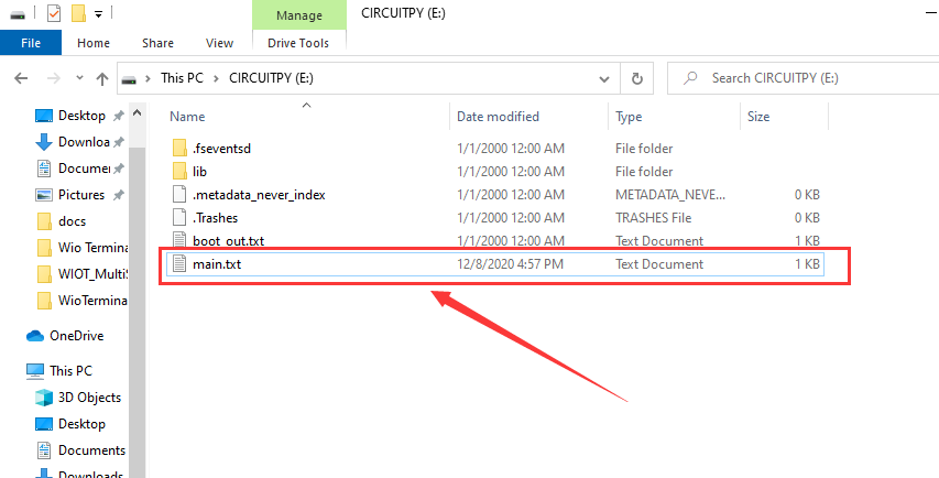
mainの名前は次のいずれかです:code.txt、code.py、main.py、main.txt。この動作についての詳細があります。
ステップ 2 REPLを使用してオレンジLEDのピンを取得します。REPLの詳細については、Welcome to CircuitPython!を参照してください。REPLを使用するには、まずシリアルコンソールに接続する必要があります。接続が確立されたら、CTRL+Cを2回押して編集モードに入ります。次に、以下のコードをコピーしてそれぞれ入力します。
>>> import board
>>> dir(board)
コードで使用可能なボード上のすべてのピンのリストが表示されます。各ボードは利用可能なピン数によって若干異なります。

YELLOW_LED_INVERTEDが見えますか?それがオレンジLEDを点滅させるために使用したピンです!
ステップ 3 mainファイルにコードを貼り付けて保存すると、Seeed Studio XIAO SAMD21ボード上のオレンジLEDが点滅するのが見えます。
コード
import time
import board
from digitalio import DigitalInOut, Direction

led = DigitalInOut(board.YELLOW_LED_INVERTED)
led.direction = Direction.OUTPUT

while True:
    led.value = True
    time.sleep(1)
    led.value = False
    time.sleep(1)
CircuitPython 用 MicroSD カード
Seeed Studio XIAO SAMD21には約40KBのフラッシュが内蔵されていますが、大きなサイズのPythonコードファイルを保存するには十分なスペースがない場合があります。幸い、Seeed Studio XIAO SAMD21拡張ボードには保存スペースを拡張するためのMicroSDカードスロットが内蔵されているので、この手順に従ってMicroSDカード上でCircuitPythonを実行する方法を学ぶことができます。
MicroSDカードのシステム形式はFATまたはexFATです。他のMicroSDカードシステム形式を使用すると、MicroSDカードが認識されない原因となります。
ステップ 1. Seeed Studio XIAO SAMD21拡張ボードに差し込むマイクロSDカードを準備します。
ステップ 2. まだCircuitPythonファイルをダウンロードしていない場合は、CircuitPythonのインストールの章を参照してください。
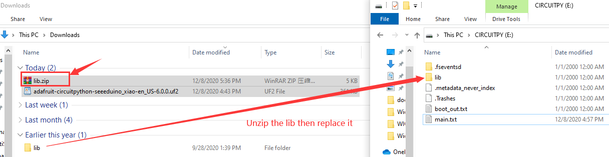
ステップ 3. libをダウンロードしてファイルを解凍し、CIRCUITPY内の新しいlibと置き換えます。
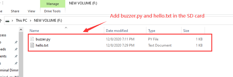
ステップ 4. main.pyファイルをCIRCUITPYドライブにダウンロードします。
main.pyコード
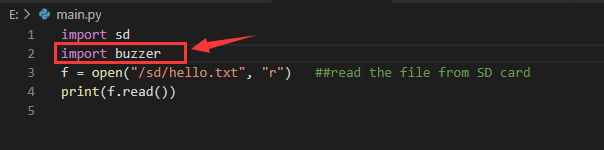
import sd
f = open("/sd/hello.txt", "r")   ## read the file from SD card
print(f.read())
ステップ 5. sd.pyファイルをCIRCUITPYドライブにダウンロードします。
sd.pyコード
import os
import adafruit_sdcard
import board
import busio
import digitalio
import storage
import sys

# Connect to the card and mount the filesystem for Seeed Studio XIAO .
spi = busio.SPI(board.SCK, board.MOSI, board.MISO)
cs = digitalio.DigitalInOut(board.D2)
sdcard = adafruit_sdcard.SDCard(spi, cs)
vfs = storage.VfsFat(sdcard)
storage.mount(vfs, "/sd")
sys.path.append("/sd")
sys.path.append("/sd/lib")  ## switch to the path to SD card
ブザーサンプル
これはMicroSDカード内のbuzzer.pyを実行してブザーをテストするサンプルです。
ステップ 1. buzzer.pyをMicroSDカードに貼り付けるだけです。
ステップ 2. CIRCUITPYドライブ内のmain.pyを開きます。
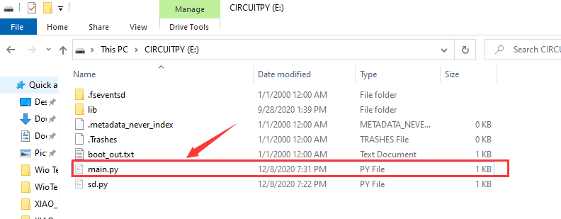
ステップ 3. main.pyファイルにimport buzzerを追加します。
すべてのステップを完了すると、ブザーが動作します。MicroSDカード内の他のPythonファイルを実行したい場合は、このサンプルを参考にしてください。
Arduinoモードに戻りたい場合は、Arduino IDEで任意のプログラムをアップロードするだけです。
デモ
プロジェクト 1 - リモコン扇風機
概要
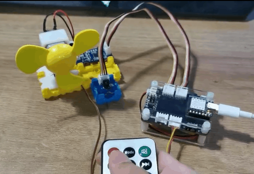
このwikiでは、部屋を涼しく保つためのミニ扇風機の作り方を紹介します。
機能
- 自動首振り扇風機
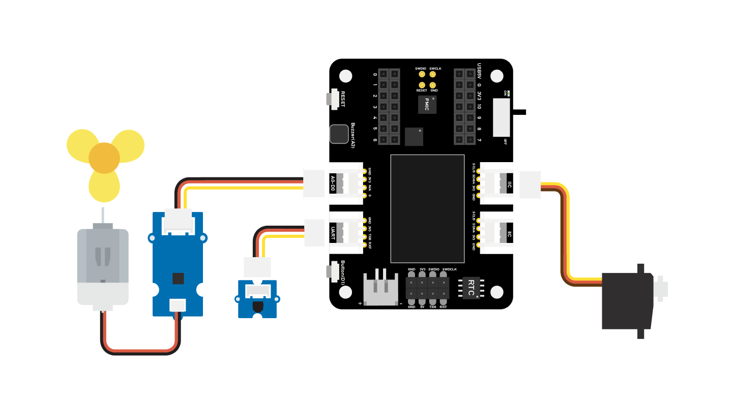
必要なコンポーネント
ハードウェア接続
同じ色の線に従って、各センサーをボードに接続してください。ファンのGroveケーブルをD0に、サーボのGroveケーブルをI2Cに、IRのGroveケーブルをD7に接続してください。
Arduino 手順
ステップ 1. 接続図に従って、すべてのセンサーをボードに接続します。
ステップ 2. Arduino-IRremote ライブラリをインストールします。こちらがライブラリのインストール方法のガイドです。
ステップ 3. コードをコピーして Arduino IDE に貼り付け、アップロードします。
ステップ 4. ファンを安全な位置に置き、ボタンを押して安全に動作することを確認してください。
コード
#include <IRremote.h>
#include <Servo.h>

Servo myservo;  // create servo object to control a servo
int RECV_PIN = 7; // set pin 2 as IR control

IRrecv irrecv(RECV_PIN);

decode_results results;

int pos = 90;    // variable to store the servo position
int fanPin = 0;  // set D6 as control switch
int fanState = LOW;
int IO = 0;

void setup()
{
  Serial.begin(9600);
  Serial.println("Enabling IRin");  // remind enabling IR
  irrecv.enableIRIn(); // Start the receiver
  Serial.println("Enabled IRin");
  myservo.attach(5);  // attaches the servo on pin 2 to the servo object
  pinMode(fanPin, OUTPUT);

}

void loop() {
  if (irrecv.decode(&results)) { //checking IR signal
    if (results.value == 2155829415) {    // Power off/on
      IO++;
      if (IO % 2 == 0) {
        fanState = HIGH;
        digitalWrite(fanPin, fanState);
        delay(100);
      }
      else {
        fanState = LOW;
        digitalWrite(fanPin, fanState);
        delay(100);
      }
    }

    if (results.value == 2155821255 ) {    // fan swing to left
      for (pos; pos <= 89; pos += 1) { // goes from 0 degrees to 90 degrees
        // in steps of 1 degree
        myservo.write(pos);              // tell servo to go to position in variable 'pos'

        delay(40);                       // waits 15ms for the servo to reach the position
        if (irrecv.decode(&results)) {
          irrecv.resume();
          if (results.value == 2155870215)
            break;
        }
      }
    }

    if (results.value == 2155870215 ) {    // fan swing to right
      for (pos; pos >= 1; pos -= 1) { // goes from 90 degrees to 0 degrees
        myservo.write(pos);              // tell servo to go to position in variable 'pos'
        delay(40);                       // waits 15ms for the servo to reach the position

        if (irrecv.decode(&results)) {
          irrecv.resume();
          if (results.value == 2155821255)
            break;
        }
      }
    }
    Serial.println(pos);
    Serial.println(results.value, HEX);
    Serial.println(results.value);
    irrecv.resume();                    //recive next intrustion
  }
  delay(100);
}
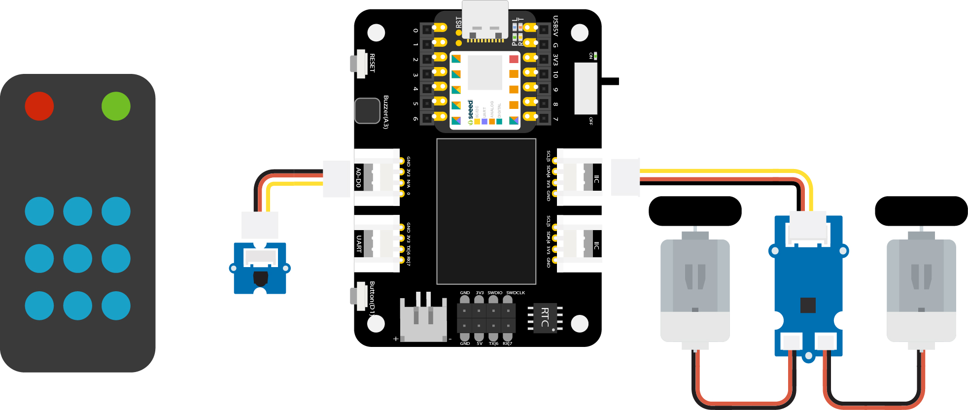
プロジェクト 2 - リモコンカー
概要
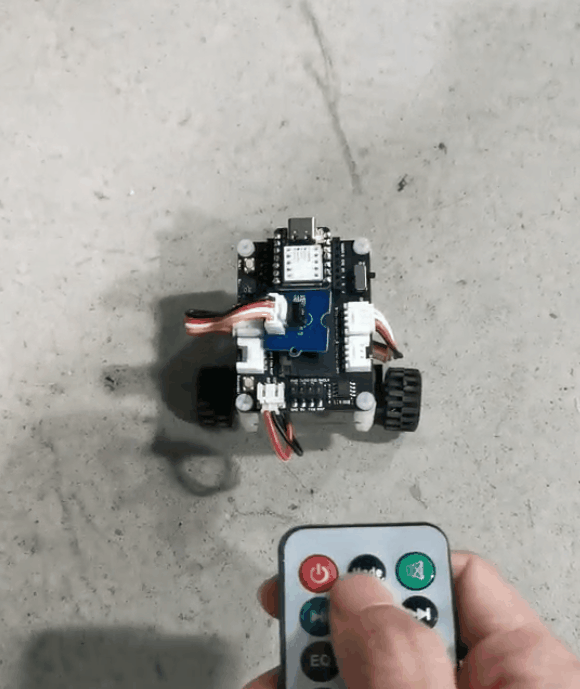
このウィキでは、リモコンカーの作り方を紹介します。
特徴
- 狭い道を簡単に通れるミニサイズのカー
必要なコンポーネント
ハードウェア接続
同じ色の線に従って、各センサーをボードに接続してください。IR センサーの Grove ケーブルを D0 に、Mini Motor Driver の Grove ケーブルを I2C に接続してください。
Arduino 手順
ステップ 1. 接続図に従って、すべてのセンサーをボードに接続します。
ステップ 2. Arduino IDE をダウンロードします。
ステップ 3. Arduino-IRremote と Motor driver ライブラリをインストールします。こちらがライブラリのインストール方法のガイドです。
ステップ 4. コードをコピーして Arduino IDE に貼り付け、アップロードします。
コード
#include <Arduino.h>
#include <U8g2lib.h>
#include <IRremote.h>
#include <SparkFunMiniMoto.h>  // Include the MiniMoto library
// Create two MiniMoto instances, with different address settings.
MiniMoto motor0(0xC4); // A1 = 1, A0 = clear
MiniMoto motor1(0xC0); // A1 = 1, A0 = 1 (default)

#define FAULTn  1     // Pin used for fault detection.

int RECV_PIN = 0; // set pin 2 as IR control
IRrecv irrecv(RECV_PIN);
decode_results results;

void setup() {
  Serial.begin(9600);
  Serial.println("Enabling IRin");  // remind enabling IR
  irrecv.enableIRIn(); // Start the receiver
  pinMode(FAULTn, INPUT);
}

void loop() {
  if (irrecv.decode(&results)) { //checking IR signal
    if (results.value == 2155862055) {
      //Forward  2155862055
      motor0.drive(-600);
      motor1.drive(600);
      delayUntil(20);
    }
    if (results.value == 2155813095) {
      //Brake   2155813095
      motor0.brake();
      motor1.brake();
      delay(100);
    }
    if (results.value == 2155823295) {
      //backward  2155823295
      motor0.drive(600);
      motor1.drive(-600);
      delayUntil(20);
    }
    if (results.value == 2155829415) {
      //Stop  2155829415
      motor0.stop();
      motor1.stop();
      delay(100);
    }
    if (results.value == 2155821255) {
      //turn right   2155821255
      motor0.drive(600);
      motor1.drive(600);
      delayUntil(20);
    }
    if (results.value == 2155837575) {
      //turn left    2155837575
      motor0.drive(-600);
      motor1.drive(-600);
      delayUntil(20);
    }
    irrecv.resume();                    //recive next intrustion

  }
  delay(100);
}

void delayUntil(unsigned long elapsedTime) {
  unsigned long startTime = millis();
  while (startTime + elapsedTime > millis()) {
    if (digitalRead(FAULTn) == LOW) {
      byte result = motor0.getFault();
      result = motor1.getFault();
    }
  }
}
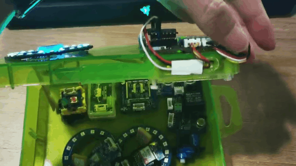
プロジェクト 3 - 指紋認証宝箱 - Seeed Studio XIAO
概要
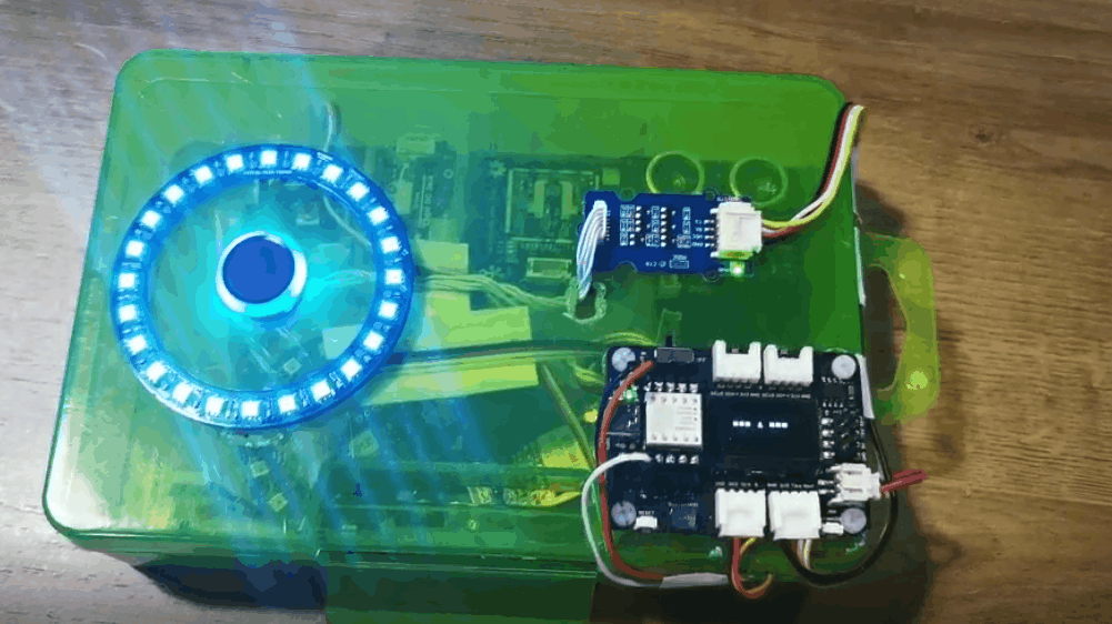
この箱は重要なものを保管でき、誰かがあなたのものを取ることを心配する必要がありません。この箱には指紋認証機能があり、あなたのものを保護します。指紋認証に失敗した場合、ブザーがアラームを鳴らし、LED リングが赤色を表示します。最初にボードに登録された指紋のみが認証され、指紋認証が通ると LED リングが緑色を表示します。
特徴
- 指紋の登録が簡単
- LED リングでロック状態を確認可能
- OLED スクリーンで現在の情報を表示
- ブザーで指紋認証の成否を通知
必要なコンポーネント
ハードウェア接続
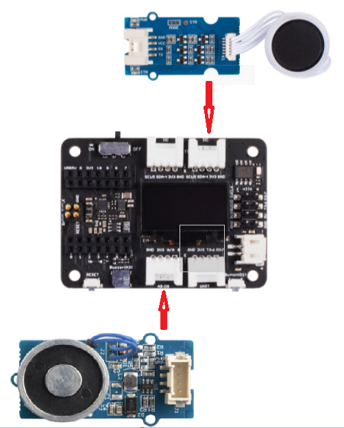
図に示すように、各モジュールをボードに接続してください。指紋モジュールを XIAO 拡張ボードの UART ポートに、サーボを XIAO 拡張ボードの D0 ポートに接続してください。
NeoPixel リングは 3 本の異なる色のワイヤーを通じて XIAO 開発ボードのピンに直接接続されることに注意してください:NeoPixel リングの DIN ピンを黄色のワイヤーで XIAO の D1 ピンに、NeoPixel リングの VIN ピンを赤いワイヤーで XIAO の 3V3 ピンに、NeoPixel リングの GND ピンを黒いワイヤーで XIAO の GND ピンに接続します。

Arduino 手順
ステップ 1. 接続図に従って、すべてのセンサーをボードに接続します。
ステップ 2. Arduino IDE をダウンロードします。
ステップ 3. u8g2、Servo、Seeed_Arduino_KCT202、Seeed_LED_Ring ライブラリをインストールします。こちらがライブラリのインストール方法のガイドです。
ステップ 4. コードをコピーして Arduino IDE に貼り付け、アップロードします。
デモンストレーション
- 指紋の登録
最初に画面に指紋記録が表示されます。指紋デバイスに指を置くだけで、プログラムが指紋を分析し、登録が完了します。
- 身元認証(認証通過)
画面に "Please verify" が表示されます。指紋デバイスに指を置くと、LED リングが緑色に変わります。
- 身元認証(認証失敗)
他の人が指を置くと、LEDリングが赤色に変わり、ボードに「Identity deny」が表示され、同時にアラームが作動します。
コード
#include <Servo.h>
#include <Arduino.h>
#include <U8x8lib.h>
#include "ATSerial.h"
#include "Protocol.h"
#include "KCT202.h"
#include "Adafruit_NeoPixel.h"

#define PIXEL_PIN    2    // Digital IO pin connected to the NeoPixels.
#define PIXEL_COUNT 24
#define debug SerialUSB
#define uart  Serial1
FingerPrint_KCT202<Uart, Serial_> kct202;
Adafruit_NeoPixel strip = Adafruit_NeoPixel(PIXEL_COUNT, PIXEL_PIN, NEO_GRB + NEO_KHZ800);

Servo myservo;

Protocol_oprt oprt;
uint8_t err_code = 0;
uint8_t param[10];
uint32_t param_len;
int pos = 0;
const int buttonPin = 1;
int buttonState = 0;
int BuzzerPin = A3;

U8X8_SSD1306_128X64_NONAME_HW_I2C u8x8(/* reset=*/ U8X8_PIN_NONE);

void setup(void) {
  Serial.begin(115200);
  strip.setBrightness(255);
  strip.begin();
  strip.show(); // Initialize all pixels to 'off'
  colorWipe(strip.Color(125, 0, 125), 50);
  u8x8.begin();
  u8x8.setFlipMode(0);
  debug.begin(115200);
  pinMode(buttonPin, INPUT_PULLUP);
  pinMode(BuzzerPin, OUTPUT);
  kct202.begin(uart, debug);
  myservo.attach(0);
  myservo.write(0);
  kct202.autoRegisterFingerPrint(1, 4, LED_OFF_AFTER_GET_GRAGH | PRETREATMENT_GRAGH | NOT_RET_FOR_EVERY_STEP | OVERRIDE_CURR_FINGER_PRINT);

  u8x8.setFont(u8x8_font_chroma48medium8_r);
  u8x8.setCursor(0, 3);
  u8x8.print("finger recording");
  if (0 == kct202.getRegisterResponAndparse()) {
    debug.println("Register ok!");
    u8x8.setFont(u8x8_font_chroma48medium8_r);
    u8x8.setCursor(0, 3);
    u8x8.print("    be ready    ");
    delay(500);
    colorWipe(strip.Color(0, 125, 125), 50);
    u8x8.setCursor(0, 3);
    u8x8.print("   *** 3 ***    ");
    delay(500);
    u8x8.setCursor(0, 3);
    u8x8.print("   *** 2 ***    ");
    delay(500);
    u8x8.setCursor(0, 3);
    u8x8.print("   *** 1 ***    ");
    delay(500);
    u8x8.setCursor(0, 3);
    u8x8.print("   Registered");
    delay(800);
  }
}

void loop(void) {
  uint16_t finger_num = 0;

  kct202.autoVerifyFingerPrint(CHECK_ALL_FINGER_TEMP,
                               LED_OFF_AFTER_GET_GRAGH | PRETREATMENT_GRAGH | NOT_RET_FOR_EVERY_STEP);
  u8x8.setFont(u8x8_font_chroma48medium8_r);
  u8x8.setCursor(0, 3);
  u8x8.print(" Please verify  ");

  if (0 == kct202.getVerifyResponAndparse(finger_num)) {
    debug.println("Verify ok!");
    debug.print("Your finger temp id = ");
    debug.println(finger_num, HEX);
    colorWipe(strip.Color(0, 255, 30), 50);
    u8x8.setFont(u8x8_font_chroma48medium8_r);
    u8x8.setCursor(0, 3);
    u8x8.print("Identity comfirm");
    delay(800);

    analogWrite(BuzzerPin, 128);
    delay(100);
    analogWrite(BuzzerPin, 0);
    delay(100);
    analogWrite(BuzzerPin, 128);
    delay(100);
    analogWrite(BuzzerPin, 0);
    delay(100);

    for (pos = 0; pos <= 90; pos += 1) {
      myservo.write(pos);
      delay(15);
    }
    while (1) {
      //      pinMode(buttonPin, INPUT);
      buttonState = digitalRead(buttonPin);
      u8x8.setFont(u8x8_font_chroma48medium8_r);
      u8x8.setCursor(0, 3);
      u8x8.print("Please close    ");
      Serial.println(pos);
      Serial.println(buttonState);
      if (buttonState == LOW && pos == 91) {
        for (pos = 91; pos >= 0; pos -= 1) { // goes from 180 degrees to 0 degrees
          u8x8.setFont(u8x8_font_chroma48medium8_r);
          u8x8.setCursor(0, 3);
          u8x8.print("Lock closing    ");
          myservo.write(pos);              // tell servo to go to position in variable 'pos'
          delay(15);                       // waits 15ms for the servo to reach the position
        }
        colorWipe(strip.Color(255, 0, 0), 50);
        break;
      }
    }
  }

  else {
    colorWipe(strip.Color(255, 0, 0), 50);
    u8x8.setFont(u8x8_font_chroma48medium8_r);
    u8x8.setCursor(0, 3);
    u8x8.print(" Identity deny ");
    //    myservo.write(0);
    delay(200);

  analogWrite(BuzzerPin, 250);
  delay(2000);
    analogWrite(BuzzerPin, 0);
  delay(100);

    u8x8.setCursor(0, 3);
    u8x8.print("  Please retry  ");
    delay(1500);
  }
}

void colorWipe(uint32_t c, uint8_t wait) {
  for (uint16_t i = 0; i < strip.numPixels(); i++) {
    strip.setPixelColor(i, c);
    strip.show();
    delay(70);
  }
}
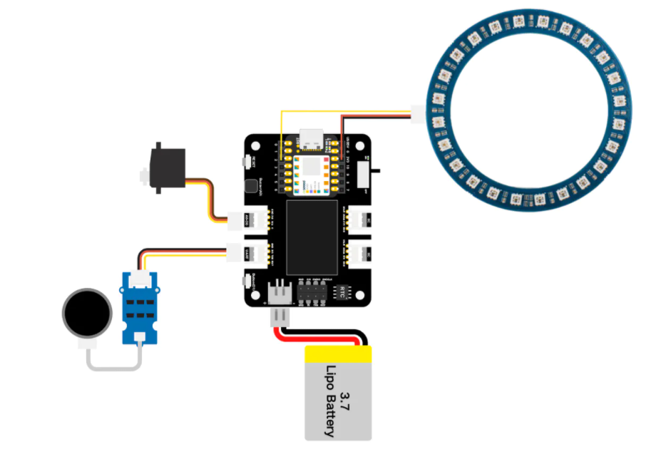
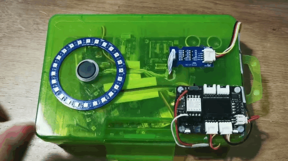
プロジェクト 4 - Seeed Studio Expansion Base for XIAO - ムジョルニア
概要
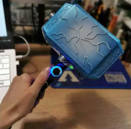
このハンマーはムジョルニアをシミュレートしたもので、このデバイスに指紋を登録することで、あなたがその主人になります。ハンマーは Grove - 電磁石に磁力で吸着されており、主人が指紋でロックを解除するまで、ハンマーを持ち去ることはできません。
必要なコンポーネント
ハードウェア接続
拡張ボードと必要なモジュールを Grove ワイヤーで接続してください。Grove 電磁石モジュールを D0 ポートに、指紋モジュールを I2C ポートに接続してください。
Arduino 手順
ステップ 1. 接続図に従って、すべてのセンサーをボードに接続してください。
ステップ 2. Arduino IDE をダウンロードしてください。
ステップ 3. u8g2 と Seeed_Arduino_KCT202 ライブラリをインストールしてください。こちらが ライブラリのインストール方法 のガイドです。
ステップ 4. コードをコピーして Arduino IDE に貼り付け、アップロードしてください。
コード
#include <U8x8lib.h>
#include "ATSerial.h"
#include "Protocol.h"
#include "KCT202.h"

#define debug SerialUSB
#define uart  Serial1
FingerPrint_KCT202<Uart, Serial_> kct202;

Protocol_oprt oprt;
uint8_t err_code = 0;
uint8_t param[10];
uint32_t param_len;

int Electromagnet = 0;

U8X8_SSD1306_128X64_NONAME_HW_I2C u8x8(/* reset=*/ U8X8_PIN_NONE);

// the setup routine runs once when you press reset:
void setup() {
  // initialize the digital pin as an output.

  u8x8.begin();
  u8x8.setFlipMode(0);
  debug.begin(115200);
  pinMode(Electromagnet, OUTPUT);
  digitalWrite(Electromagnet, HIGH);  // turn the Electromagnet on (HIGH is the voltage level)
  kct202.begin(uart, debug);
  kct202.autoRegisterFingerPrint(1, 4, LED_OFF_AFTER_GET_GRAGH | PRETREATMENT_GRAGH | NOT_RET_FOR_EVERY_STEP | OVERRIDE_CURR_FINGER_PRINT);
  u8x8.setFont(u8x8_font_chroma48medium8_r);
  u8x8.setCursor(0, 3);
  u8x8.print("finger recording");
  if (0 == kct202.getRegisterResponAndparse()) {
    u8x8.setFont(u8x8_font_chroma48medium8_r);
    u8x8.setCursor(0, 3);
    u8x8.print("    be ready    ");
    delay(500);
    u8x8.setCursor(0, 3);
    u8x8.print("   *** 3 ***    ");
    delay(500);
    u8x8.setCursor(0, 3);
    u8x8.print("   *** 2 ***    ");
    delay(500);
    u8x8.setCursor(0, 3);
    u8x8.print("   *** 1 ***    ");
    delay(500);
    u8x8.setCursor(0, 3);
    u8x8.print("   Registered");
    delay(800);
  }

}

  // the loop routine runs over and over again forever:
  void loop() {

    uint16_t finger_num = 0;
    kct202.autoVerifyFingerPrint(CHECK_ALL_FINGER_TEMP, LED_OFF_AFTER_GET_GRAGH | PRETREATMENT_GRAGH | NOT_RET_FOR_EVERY_STEP);
    u8x8.setFont(u8x8_font_chroma48medium8_r);
    u8x8.setCursor(0, 3);
    u8x8.print(" Please verify  ");

    if (0 == kct202.getVerifyResponAndparse(finger_num)) {
      u8x8.setFont(u8x8_font_chroma48medium8_r);
      u8x8.setCursor(0, 3);
      u8x8.print("Identity comfirm");
      delay(800);
      digitalWrite(Electromagnet, LOW);  // turn the Electromagnet on (HIGH is the voltage level)
      delay(5000);
      digitalWrite(Electromagnet, HIGH);
    }

    else {
      u8x8.setFont(u8x8_font_chroma48medium8_r);
      u8x8.setCursor(0, 3);
      u8x8.print(" Identity deny ");
      //    myservo.write(0);
      delay(200);

      u8x8.setCursor(0, 3);
      u8x8.print("  Please retry  ");
      delay(1500);
      digitalWrite(Electromagnet, HIGH);  // turn the Electromagnet on (HIGH is the voltage level)

    }
  }
プロジェクト 5 - 空気質センサーハブ - Seeed Studio Expansion Base for XIAO
概要
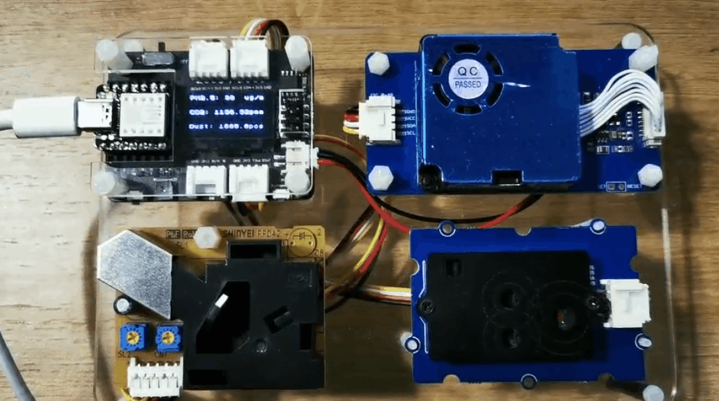
これは、Grove - レーザー PM2.5 センサー、Grove - CO2・温度・湿度センサー、Grove - ダストセンサーを使用して、PM2.5、PM10、温度、湿度、CO2、ダスト粒子をそれぞれ収集する環境検出デバイスです。
必要なコンポーネント
-
Seeed Grove - CO2 & Temperature & Humidity Sensor for Arduino (SCD30) - 3-in-1
-
Seeed Grove - Laser PM2.5 Dust Sensor - Arduino Compatible - HM3301
ハードウェア接続
図に示すように各センサーを接続してください。CO2センサーとPM2.5センサーをそれぞれ2つのI2Cポートに接続し、ダストセンサーをUARTポートに接続してください。
Arduino 手順
ステップ 1. 接続図に従って、すべてのセンサーをボードに接続してください。
ステップ 2. Aruidno IDE をダウンロードしてください
ステップ 3. u8g2、Seeed_PM2_5_sensor_HM3301、Seeed_SCD30 ライブラリをインストールしてください。こちらが ライブラリのインストール方法 のガイドです。
ステップ 4. コードをコピーしてArduino IDEに貼り付け、アップロードしてください。
コード
#include <Arduino.h>
#include <U8x8lib.h>
#include <Seeed_HM330X.h>
#include "SCD30.h"

#define SERIAL_OUTPUT SerialUSB
#define SERIAL SerialUSB

int pin = 7;
unsigned long duration;
unsigned long starttime;
unsigned long sampletime_ms = 5000;//sampe 30s ;
unsigned long lowpulseoccupancy = 0;
float ratio = 0;
float concentration = 0;

const int buttonPin = 1;
int buttonState = 0;
int memu = 0;

U8X8_SSD1306_128X64_NONAME_HW_I2C u8x8(/* reset=*/ U8X8_PIN_NONE);
HM330X sensor;
uint8_t buf[30];

const char* str[] = {"sensor num: ", "PM1.0 concentration(CF=1,Standard particulate matter,unit:ug/m3): ",
                     "PM2.5 concentration(CF=1,Standard particulate matter,unit:ug/m3): ",
                     "PM10 concentration(CF=1,Standard particulate matter,unit:ug/m3): ",
                     "PM1.0 concentration(Atmospheric environment,unit:ug/m3): ",
                     "PM2.5 concentration(Atmospheric environment,unit:ug/m3): ",
                     "PM10 concentration(Atmospheric environment,unit:ug/m3): ",
                    };


///////////////////////////////////////////////////////////////////
//PM2.5 concentration(Atmospheric environment,unit:ug/m3): value
///////////////////////////////////////////////////////////////////
HM330XErrorCode print_result(const char* str, uint16_t value) {
  if (NULL == str) {
    return ERROR_PARAM;
  }
  //  SERIAL_OUTPUT.print(str);
  u8x8.setFont(u8x8_font_chroma48medium8_r);
  u8x8.setCursor(0, 0);
  u8x8.print("PM2.5: ");
  u8x8.setCursor(7, 0);
  u8x8.print(value);
  u8x8.setCursor(11, 0);
  u8x8.print("ug/m");
  Serial.println(value);
  return NO_ERROR;
}

HM330XErrorCode print_result_1(const char* str, uint16_t value) {
  if (NULL == str) {
    return ERROR_PARAM;
  }
  //  SERIAL_OUTPUT.print(str);
  u8x8.setFont(u8x8_font_chroma48medium8_r);
  u8x8.setCursor(0, 0);
  u8x8.print("PM10: ");
  u8x8.setCursor(7, 0);
  u8x8.print(value);
  u8x8.setCursor(11, 0);
  u8x8.print("ug/m");
  Serial.println(value);
  return NO_ERROR;
}

/*parse buf with 29 uint8_t-data*/
HM330XErrorCode parse_result(uint8_t* data) {
  uint16_t value = 0;
  if (NULL == data) {
    return ERROR_PARAM;
  }
  value = (uint16_t) data[6 * 2] << 8 | data[6 * 2 + 1];
  print_result(str[6 - 1], value);
  return NO_ERROR;
}


HM330XErrorCode parse_result2(uint8_t* data) {
  uint16_t value = 0;
  if (NULL == data) {
    return ERROR_PARAM;
  }
  value = (uint16_t) data[7 * 2] << 8 | data[7 * 2 + 1];
  print_result_1(str[7 - 1], value);
  return NO_ERROR;
}

////////////////////////////////////////////////////////////////////

/*30s*/
void setup() {
  Serial.begin(115200);
  Wire.begin();
  u8x8.begin();
  u8x8.setFlipMode(0);
  scd30.initialize();
  pinMode(pin, INPUT);
  pinMode(buttonPin, INPUT_PULLUP);
  starttime = millis();//get the current time;

}

void loop() {
  float result[3] = {0};
  duration = pulseIn(pin, LOW);
  lowpulseoccupancy = lowpulseoccupancy + duration;

  buttonState = digitalRead(buttonPin);

  if (buttonState == LOW) {
    memu++;
    delay(15);
    if (memu == 2) {
      memu = 0;
    }
  }
  Serial.println(memu);

  if (scd30.isAvailable() && memu == 0) {
    scd30.getCarbonDioxideConcentration(result);
    u8x8.setFont(u8x8_font_chroma48medium8_r);
    u8x8.setCursor(0, 3);
    u8x8.print("CO2: ");
    u8x8.setCursor(5, 3);
    u8x8.print(result[0]);
    u8x8.setCursor(12, 3);
    u8x8.print("pmm");
    delay(1000);
  }

  if (sensor.read_sensor_value(buf, 29) && memu == 0) {
    SERIAL_OUTPUT.println("HM330X read result failed!!!");
  }
  if(memu == 0){
  parse_result(buf);
  }

  if ((millis() - starttime) > sampletime_ms  && memu == 0) {
    ratio = lowpulseoccupancy / (sampletime_ms * 10.0); // Integer percentage 0=>100
    concentration = 1.1 * pow(ratio, 3) - 3.8 * pow(ratio, 2) + 520 * ratio + 0.62; // using spec sheet curve

    u8x8.setFont(u8x8_font_chroma48medium8_r);
    u8x8.setCursor(0, 6);
    u8x8.print("Dust: ");

    u8x8.setCursor(6, 6);
    u8x8.print(concentration);

    u8x8.setCursor(12, 6);
    u8x8.print("pcs");

    //    Serial.println(concentration);
    lowpulseoccupancy = 0;
    starttime = millis();
  }


  if (scd30.isAvailable() && memu == 1) {
    scd30.getCarbonDioxideConcentration(result);
    u8x8.setFont(u8x8_font_chroma48medium8_r);
    u8x8.setCursor(0, 3);
    u8x8.print("Temp: ");
    u8x8.setCursor(6, 3);
    u8x8.print(result[1]);
    u8x8.setCursor(10, 3);
    u8x8.print(" C   ");

    u8x8.setCursor(0, 6);
    u8x8.print("Humi: ");
    u8x8.setCursor(5, 6);
    u8x8.print(result[2]);
    u8x8.setCursor(8, 6);
    u8x8.print("  %     ");

    delay(1000);
  }

  if (sensor.read_sensor_value(buf, 29) && memu == 1) {
    SERIAL_OUTPUT.println("HM330X read result failed!!!");
  }
  if(memu == 1){
  parse_result2(buf);
  }
}
プロジェクト 6 - Seeed Studio Expansion Base for XIAO - 心拍数
概要
このシンプルで安価なプロジェクトは、Seeed Studio Expansion Base for XIAOを基に心拍数を報告します。 使用するデバイスはI2C 2線式インターフェースを持っているため、配線を最小限に抑えることができます。
必要なコンポーネント
ハードウェア接続
下図に示すように、心拍数センサーをXIAO拡張ボードのI2Cインターフェースに接続してください。
Arduino 手順
ステップ 1. 接続図に従って、すべてのセンサーをボードに接続してください。
ステップ 2. Aruidno IDE をダウンロードしてください
ステップ 3. u8g2 ライブラリをインストールしてください。こちらが ライブラリのインストール方法 のガイドです。
ステップ 4. コードをコピーしてArduino IDEに貼り付け、アップロードしてください。
コード
#include <Arduino.h>
#include <U8x8lib.h>

#include <Wire.h>

U8X8_SSD1306_128X64_NONAME_HW_I2C u8x8(/* reset=*/ U8X8_PIN_NONE);

void setup() {
  Serial.begin(9600);
  Serial.println("heart rate sensor:");

  u8x8.begin();
  u8x8.setFlipMode(1);
  Wire.begin();
}
void loop() {
  Wire.requestFrom(0xA0 >> 1, 1);    // request 1 bytes from slave device
  while (Wire.available()) {         // slave may send less than requested
    unsigned char c = Wire.read();   // receive heart rate value (a byte)
    u8x8.setFont(u8x8_font_chroma48medium8_r);
//    u8x8.setCursor(0, 3);
//    u8x8.print("blood detecting ");
//    delay(10000);

    u8x8.setCursor(0, 3);
    u8x8.print("HeartRate: ");
    u8x8.setCursor(10, 3);
    u8x8.print(c);
    u8x8.setCursor(13, 3);
    u8x8.print("bpm");
    Serial.println(c);

  }
  delay(500);
}
リソース
- [PDF]ETA1038
- [PDF]ETA3410
- [PDF]ETA6003
- [PDF]PCF8563T
- [PDF]Seeed Studio Expansion Base for XIAO_v1.0_SCH_200824
- [SCH]Seeed Studio Expansion Base for XIAO_v1.0_200824
- [BRD]Seeed Studio Expansion Base for XIAO_v1.0_200824
FAQ
Q1: XIAO拡張ボード上のPMICは5Vピンに電力を出力しますか?
PMICは電力を出力しません。5VはUSBから直接供給されます。5Vピンで提供される電流は、USB接続から利用可能な電流と同等です。
技術サポート & 製品ディスカッション
弊社製品をお選びいただき、ありがとうございます!お客様の製品体験が可能な限りスムーズになるよう、さまざまなサポートを提供いたします。異なる好みやニーズに対応するため、複数のコミュニケーションチャンネルをご用意しています。