MyActuator Xシリーズモーター入門
この記事では、MyActuatorシリーズモーターの使い方と、reComputer Mini Jetson OrinでC++およびPythonを使用する方法を紹介します。

仕様
以下は、すべてのモーターモデルのパラメータを記載した完全な表です:
| パラメータ | X2-7 | X4-10 | X4-36 | X8-120 | X12-320 | X15-450 |
|---|---|---|---|---|---|---|
| ギア比 | 28.17 | 12.6 | 36 | 19.61 | 20 | 20.25 |
| 入力電圧 (V) | 24 | 24 | 24 | 48 | 48 | 72 |
| 無負荷速度 (RPM) | 178 | 317 | 111 | 158 | 125 | 108 |
| 無負荷入力電流 (A) | 1 | 1 | 0.9 | 1.6 | 2.7 | 3.5 |
| 定格速度 (RPM) | 142 | 238 | 83 | 127 | 100 | 98 |
| 定格トルク (N.m) | 2.5 | 4 | 10.5 | 43 | 85 | 145 |
| 定格出力 (W) | 37 | 100 | 100 | 574 | 900 | 1480 |
| 定格相電流 A(rms) | 3 | 7.8 | 6.1 | 17.6 | 30 | 25 |
| ピークトルク (N.m) | 7 | 10 | 34 | 120 | 320 | 450 |
| ピーク相電流 A(rms) | 8.1 | 19.5 | 21.5 | 43.8 | 100 | 69.2 |
| 効率 (%) | 63 | 69.5 | 63.1 | 79 | 75 | 82.4 |
| モーター逆起電力定数 (Vdc/Krpm) | 4.3 | 6 | 6 | 19.2 | 17.9 | 29.9 |
| モジュールトルク定数 (N.m/A) | 0.8 | 0.8 | 1.9 | 2.4 | 3.3 | 5.8 |
| モーター相抵抗 (Ω) | 0.61 | 0.32 | 0.35 | 0.18 | 0.12 | 0.08 |
| モーター相インダクタンス (mH) | 0.13 | 0.14 | 0.17 | 0.31 | 0.05 | 0.14 |
| 極対数 | 13 | 13 | 13 | 10 | 20 | 20 |
| 3相接続 | Y | |||||
| バックドライブトルク (N.m) | 0.4 | 0.8 | 1.14 | 3.21 | 3.8 | 4 |
| バックラッシュ (Arcmin) | 12 | 10 | 10 | 10 | 10 | 10 |
| 出力ベアリングタイプ | 深溝玉軸受 | クロスローラーベアリング | ||||
| 軸方向荷重 (KN) | 0.25 | 1.2 | 1.3 | 4 | 4.5 | 5.4 |
| 軸方向応力 (KN) | 0.25 | 1.2 | 1.3 | 1 | 4.5 | 5.4 |
| ラジアル荷重 (KN) | 1 | 1.2 | 1.5 | 4.5 | 5 | 6 |
| 慣性 (Kg.cm²) | 0.17 | 0.25 | 0.3 | 1.5 | 12.9 | 31.6 |
| エンコーダータイプ・インターフェース | デュアルエンコーダー ABS-17BIT (入力) / 17-18BIT (出力) | |||||
| 制御精度 (度) | <0.01 | |||||
| 通信 | CAN BUS / EtherCAT | |||||
| 重量 (Kg) | 0.26 | 0.33 | 0.36 | 1.40 | 2.37 | 3.50 |
| 絶縁等級 | F | |||||
RMD-X V4シリーズ命名規則
- RMD: ブランド名 R-Reducer M-Motor D-Drive
- X2: Xはシリーズ名を表す:統合プラネタリーアクチュエーター、2はモーターモデル番号を表す(例:X2 X4 X6 X8など)
- P28: プラネタリーギア比(例:P12 P28 P32など)
- 7: ピークトルク 7N.m
- E: 通信 E: CAN BUS & EtherCAT
主な特徴
- CAN BUS & EtherCAT
- クロスローラーベアリング
- デュアルエンコーダー
- 高トルク密度
- 高精度
- 中空設計
入門
使用前の環境準備
PCのWindowsシステム
-
対応する製品マニュアルをダウンロードしてください。
-
MYACTUATOR_Setup Software_V4.0.zipをダウンロードしてください。
-
MYACTUATOR_Setup Software_V4.0.zipを展開し、以下をインストールしてください:Required Runtime Environment\ZLGUSBCAN_DriverディレクトリにあるUSBCAN_AllInOne_x86_x64_2.0.0.1.exeRequired Microsoft Runtime LibrariesディレクトリにあるMSVBCRT.AIO.2019.10.19.X86 X64.exe
回路の接続
ここではX4-36モーターを選択し、そのインターフェース図を以下に示します。

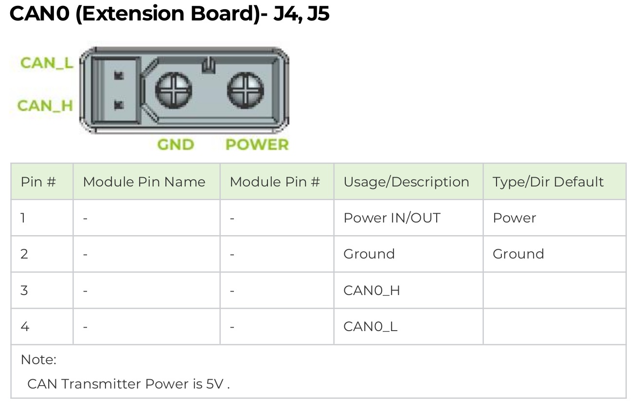
| ポート定義 | ポート説明 |
|---|---|
| ① VCC | 電源正極 |
| ② GND | 電源負極 |
| ③ CAN_H | CAN_Hネットワーク信号端子 |
| ④ CAN_L | CAN_Lネットワーク信号端子 |
| ⑤ EtherCAT_IN | EtherCAT入力端子 |
| ⑥ EtherCAT_OUT | EtherCAT出力端子 |
| ⑦ T+ | マスターがモジュールに制御コマンドを送信 |
| ⑧ T- | モジュールがマスターにステータスフィードバックを送信 |
| ⑨ R+ | マスターがモジュールステータスデータを反映 |
| ⑩ R- | モジュールがマスター制御コマンドを反映 |
ここでは、CAN通信方式を使用します。これには、WindowsでのPC上でのデバッグ用に追加のUSB-CANインターフェースが必要です。

ここでは、モーター用に別途24V電源を提供し、USBをコンピューターに接続する必要があります。
MYACTUATOR Setup Software 250206.exeを使用してモーターをテストする
| IDの設定と接続 | モーター情報の読み取り | モーターの校正 | モーターの校正 | モーター回転テストの実行 |
|---|---|---|---|---|
 |  |  |  |  |
| デフォルトのモーターIDは1です。IDに1を入力し、「Connect」をクリックします。 | 接続後、「Read」をクリックしてモーターの現在の情報を取得します。 | 初回使用時は、「Calibrate Motor」をクリックして校正を実行します。 | 校正後、「Read」と「Save」をクリックします。 | Motor Runningセクションで異なるモーター制御モードをテストできます。 |
詳細な機能については、MYACTUATOR_Setup Software_V4.0.zipファイルに含まれているSetup Software Instruction Manual - V3.0.pdfを参照してください。
reComputer Mini Jetson Orinを使用してモーターを制御する
現在、市場で最も一般的なモーター用CAN通信インターフェースはXT30 (2+2)とJSTコネクタを使用しています。私たちのreComputer Mini Jetson OrinとreComputer RoboticsデバイスはデュアルXT30 (2+2)ポートとJSTベースのCANインターフェースを搭載し、シームレスな互換性を提供します。
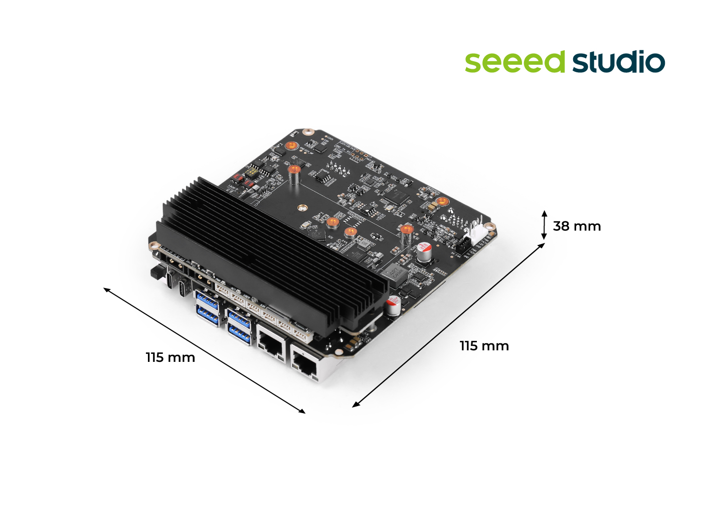
reComputer Mini:

reComputer Robotics
CAN使用の詳細については、このwikiを参照してください。
CANインターフェースの有効化
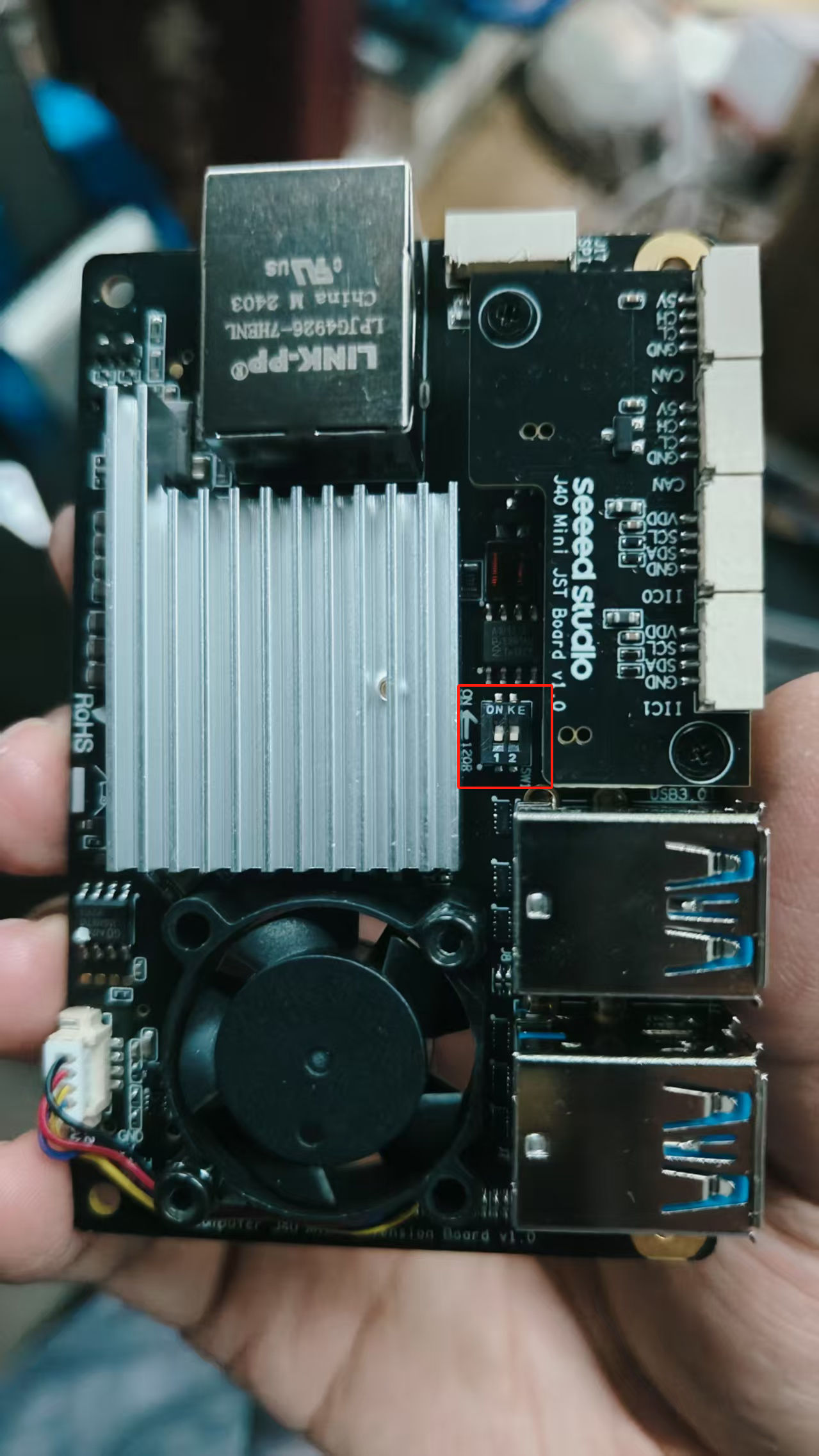
ステップ1: CAN0とCAN1を使用する前に、底面カバーを取り外し、両方の120Ω終端抵抗をON位置に設定してください。
ステップ2: XT30 (2+2)インターフェースを介してモーターをreComputer Mini CAN0に直接接続します。
これはreComputer MiniのCAN0インターフェースです

:::dangerこの電源は単一モーター学習およびテスト専用です。複数のモーターの場合は、別途電源ボードを設計し、Jetsonの電源をモーター電源から分離して、高電流がJetsonを直接通過することを避けてください。 :::
Jetson CAN通信を有効にする
ターミナルを開き、以下のコマンドを入力してGPIOピンをハイにプルし、CAN0を有効にします:
gpioset --mode=wait 0 43=0
JST-インターフェースCAN1を使用している場合は、ピン106をハイにプルします。
gpioset --mode=wait 0 106=0
このターミナルを開いたまま、新しいターミナルを起動し、CAN0を設定します。
sudo modprobe mttcan
sudo ip link set can0 type can bitrate 1000000
sudo ip link set can0 up
PythonとC++環境の構築
ステップ1: SDKをGitクローンします。
git clone https://github.com/ZhuYaoHui1998/myactuator_rmd.git
ステップ2: このドライバーSDKには以下の依存関係のインストールが必要です。Debian Linuxの場合、aptを通じて以下のようにインストールできます:
sudo apt-get install -y build-essential cmake
sudo apt install linux-modules-extra-5.15.0-1025-nvidia-tegra # For Jetson Jetpack 6.0
Pythonバインディングを使用したい場合は、追加でPython 3、pip、pybind11をインストールする必要があります:
sudo apt-get install -y python3 python3-pip python3-pybind11 python3-setuptools
依存関係をインストールした後、以下のステップで説明するように、ドライバーSDKをC++ライブラリまたはPythonパッケージとしてインストールする必要があります。どちらもCMakeを使用してC++コードをコンパイルします。
C++ライブラリのビルド
C++ドライバーSDKをビルドするには、このフォルダ内で新しいターミナルを開き、以下のコマンドを実行します。古いバージョンのLinuxでは、error: 'const struct can_frame' has no member named 'len'というエラーメッセージでビルドが失敗する場合があり、issue 5で議論されているコード修正を適用する必要があります。
cd ~/myactuator_rmd
mkdir build
cd build
cmake .. -D PYTHON_BINDINGS=on
make -j $(nproc)
sudo make install
フラグPYTHON_BINDINGS(デフォルトはオフ)は、C++ライブラリに加えてPythonバインディングもビルドします。C++ライブラリのみを使用したい場合は、オフのままにしておいてください。このようにPythonバインディングをビルドすると、共有ライブラリにコンパイルされますが、インストールはされません。つまり、ライブラリを手動でインストールするか、ビルドフォルダ内でローカルにのみインポートできます。
パッケージを再度アンインストールするには、以下のコマンドを使用できます:xargs rm < install_manifest.txt。
Pythonライブラリのビルド
このSDKのPythonバインディングをビルドしてインストールするには、メインフォルダ内で新しいターミナルを開き、以下のコマンドを実行します:
cd ~/myactuator_rmd
pip3 install .
これはsetup.pyを使用してCMakeを呼び出し、バインディングをC++ライブラリとしてインストールします。再度削除したい場合は、単純にpip3 uninstall myactuator-rmd-pyを実行してください。
C++を使用した制御
- プロジェクトディレクトリ構造の作成
コードsrcディレクトリの下にプロジェクトディレクトリを作成します。例えば、myactuator_exampleという名前にし、サブディレクトリの下にsrcフォルダを作成します。
cd ~/myactuator_rmd
mkdir -p ~/myactuator_rmd/src/myactuator_example/src
cd ~/myactuator_rmd/src/myactuator_example
- CMakeLists.txtの作成
~/myactuator_rmd/src/myactuator_example/CMakeLists.txtファイルに、以下の内容を記述します:
touch CMakeLists.txt
cmake_minimum_required(VERSION 3.20)
project(myactuator_example)

# Find the myactuator_rmd library
find_package(myactuator_rmd REQUIRED)

# Create executable
add_executable(myactuator_node
src/main.cpp
)

# Use C++17 standard
target_compile_features(myactuator_node PUBLIC
cxx_std_17
)

# Link the myactuator_rmd library
target_link_libraries(myactuator_node PUBLIC
myactuator_rmd::myactuator_rmd
)
- main.cppの作成
~/myactuator_rmd/src/myactuator_example/src/main.cppファイルに、以下のコードを記述します:
touch src/main.cpp
#include <cstdlib>
#include <iostream>
#include <myactuator_rmd/myactuator_rmd.hpp>

int main() {
myactuator_rmd::CanDriver driver {"can0"};
myactuator_rmd::ActuatorInterface actuator {driver, 1};

std::cout << actuator.getVersionDate() << std::endl;
std::cout << actuator.sendPositionAbsoluteSetpoint(180.0, 500.0) << std::endl;
actuator.shutdownMotor();
return EXIT_SUCCESS;
}
- プロジェクトのビルド
cd ~/myactuator_rmd/src/myactuator_example
mkdir build && cd build
cmake .. -DCMAKE_BUILD_TYPE=Release
make
- プログラムの実行
sudo ./myactuator_node

前提条件
- CANインターフェース
can0が適切に設定されている必要があります(モーターとCANバスが正しく接続されていることを確認してください)。 myactuator_rmdライブラリが適切にインストールされている必要があります(インストールされていない場合は、まずインストールしてください)。
C++実装の詳細については、myactuator_rmd.hppのすべての内容を参照してください。Python使用方法について詳細な紹介を提供します。
Pythonを使用した制御
~/myactuator_rmd/src/myactuator_exampleディレクトリの下にscriptsという名前のフォルダを作成し、Pythonスクリプトを保存します。
cd ~/myactuator_rmd/src/myactuator_example
mkdir scripts
バージョン番号の取得
scriptsディレクトリの下にtest.pyという名前のカスタムPythonスクリプトを作成し、以下のコードを記述します。
import myactuator_rmd_py as rmd
import time

# Initialize CAN driver and actuator interface
driver = rmd.CanDriver("can0")  # Using can0
actuator = rmd.ActuatorInterface(driver, 1)  # CAN ID set to 1

# Get version number
print("Version number:", actuator.getVersionDate())

ライブラリをロードし、特定のネットワークインターフェース(ここではcan0)とドライブ(ここでは1、CANアドレス0x140 + 1 = 0x141に対応)のドライバーを作成し続けます。
モーターステータスの取得
# -*- coding: gbk -*-
import myactuator_rmd_py as rmd
import time
driver = rmd.CanDriver("can0")
actuator = rmd.ActuatorInterface(driver, 1)

# Motor Status 1
status1 = actuator.getMotorStatus1()
print(f"""
Motor Status 1:
Temperature: {status1.temperature}°C
Brake Status: {'Released' if status1.is_brake_released else 'Locked'}
Voltage: {status1.voltage}V
Error Code: {status1.error_code}
""")

# Motor Status 2
status2 = actuator.getMotorStatus2()
print(f"""
Motor Status 2:
Temperature: {status2.temperature}°C
Current: {status2.current}A
Shaft Speed: {status2.shaft_speed} RPM
Shaft Angle: {status2.shaft_angle}°
""")

# Motor Status 3
status3 = actuator.getMotorStatus3()
print(f"""
Motor Status 3:
Temperature: {status3.temperature}°C
Phase A Current: {status3.current_phase_a}A
Phase B Current: {status3.current_phase_b}A
Phase C Current: {status3.current_phase_c}A
""")

## Torque Calculation

import myactuator_rmd_py as rmd
from myactuator_rmd_py.actuator_constants import X4_24  # Import according to your motor model

def get_normalized_torque(actuator):
    """Calculate normalized torque from current"""
    # Get current value
    status = actuator.getMotorStatus2()
    current = status.current

    # Calculate normalized torque (current/rated)
    torque_ratio = current / X4_24.rated_current
    actual_torque = torque_ratio * X4_24.rated_torque
    return actual_torque

# Usage example
driver = rmd.CanDriver("can0")
actuator = rmd.ActuatorInterface(driver, 1)

try:
    while True:
        torque = get_normalized_torque(actuator)
        print(f"Current Torque: {torque:.3f} Nm (Rated: {X4_24.rated_torque} Nm)", end='\r')
        time.sleep(0.1)
except KeyboardInterrupt:
    actuator.shutdownMotor()

制御モード
- 現在の制御モードの取得
# -*- coding: gbk -*-
import myactuator_rmd_py as rmd
import time
driver = rmd.CanDriver("can0")
actuator = rmd.ActuatorInterface(driver, 1)
mode = actuator.getControlMode()
print(f"Current Control Mode: {mode}")

- 絶対位置制御
# -*- coding: gbk -*-
import myactuator_rmd_py as rmd
import time
driver = rmd.CanDriver("can0")
actuator = rmd.ActuatorInterface(driver, 1)

# Move to 180 degree position at 100 deg/s
actuator.sendPositionAbsoluteSetpoint(180.0, 300.0)
time.sleep(5)  # Wait for motor to reach target position

# Get current position
angle = actuator.getMultiTurnAngle()
print(f"Current position: {angle}°")

time.sleep(5)
mode = actuator.getControlMode()
print(f"Current control mode: {mode}")
actuator.shutdownMotor()

モーターが180度の位置に回転するのを確認できます。
- 相対位置制御
import myactuator_rmd_py as rmd
import time
driver = rmd.CanDriver("can0")
actuator = rmd.ActuatorInterface(driver, 1)

# Move an additional 90 degrees from current position
current_angle = actuator.getMultiTurnAngle()
target_angle = current_angle + 90.0
actuator.sendPositionAbsoluteSetpoint(target_angle, 50.0)
time.sleep(3)
angle = actuator.getMultiTurnAngle()
print(f"Current position: {angle}°")
mode = actuator.getControlMode()
print(f"Current control mode: {mode}")
actuator.shutdownMotor()

モーターが反時計回りに90度回転するのを観察できます。
- 速度制御
# -*- coding: gbk -*-
import myactuator_rmd_py as rmd
import time
driver = rmd.CanDriver("can0")
actuator = rmd.ActuatorInterface(driver, 1)

# Continuous rotation at 500 RPM
actuator.sendVelocitySetpoint(500.0)
time.sleep(15)

# Stop motor
actuator.stopMotor()

# Get current position
angle = actuator.getMultiTurnAngle()
print(f"Current position: {angle}°")

mode = actuator.getControlMode()
print(f"Current control mode: {mode}")

- トルク制御
# -*- coding: gbk -*-
import myactuator_rmd_py as rmd
import time
driver = rmd.CanDriver("can0")
actuator = rmd.ActuatorInterface(driver, 1)

# Apply 0.5A current (torque)
actuator.sendCurrentSetpoint(0.5)
time.sleep(2)

# Stop torque output
actuator.stopMotor()

# Get current position
angle = actuator.getMultiTurnAngle()
print(f"Current position: {angle}°")

mode = actuator.getControlMode()
print(f"Current control mode: {mode}")

- クローズドループモーション制御
# -*- coding: gbk -*-
import myactuator_rmd_py as rmd
import time

# Initialization
driver = rmd.CanDriver("can0")
actuator = rmd.ActuatorInterface(driver, 1)

# Position control with feedback
feedback = actuator.sendPositionAbsoluteSetpoint(180.0, 100.0)
time.sleep(5)
print(feedback)


# Velocity control with feedback
feedback = actuator.sendVelocitySetpoint(20.0)
time.sleep(5)
print(feedback)

# Torque control with feedback
torque_constant = 0.32  # Set according to motor model
feedback = actuator.sendTorqueSetpoint(1.5, torque_constant)
time.sleep(5)
print(feedback)

actuator.stopMotor()

モーターブレーキ制御
# -*- coding: gbk -*-
import myactuator_rmd_py as rmd
import time
driver = rmd.CanDriver("can0")
actuator = rmd.ActuatorInterface(driver, 1)

# Engage brake
actuator.lockBrake()
print("Brake engaged")

# Release brake
actuator.releaseBrake()
print("Brake released")
モーター電源制御
# -*- coding: gbk -*-
import myactuator_rmd_py as rmd
import time
driver = rmd.CanDriver("can0")
actuator = rmd.ActuatorInterface(driver, 1)

# Power off motor
actuator.shutdownMotor()
print("Motor powered off")
エンコーダー機能
- マルチターンエンコーダー位置の取得
# -*- coding: gbk -*-
import myactuator_rmd_py as rmd
import time
driver = rmd.CanDriver("can0")
actuator = rmd.ActuatorInterface(driver, 1)
encoder_pos = actuator.getMultiTurnEncoderPosition()
print(f"Multi-turn encoder position: {encoder_pos}")
- 現在位置をゼロ点として設定(再起動が必要)
# -*- coding: gbk -*-
import myactuator_rmd_py as rmd
import time
driver = rmd.CanDriver("can0")
actuator = rmd.ActuatorInterface(driver, 1)
actuator.setCurrentPositionAsEncoderZero()
print("Current position set as encoder zero point")
- カスタムゼロ点の設定(再起動が必要)
# -*- coding: gbk -*-
import myactuator_rmd_py as rmd
import time

driver = rmd.CanDriver("can0")
actuator = rmd.ActuatorInterface(driver, 1)

# Get current position as zero point
current_pos = actuator.getMultiTurnEncoderOriginalPosition()
print(f"Raw encoder position: {current_pos}")

# Set zero offset
actuator.setEncoderZero(current_pos)
print(f"Encoder zero point set to: {current_pos}")

# Reboot to apply settings
actuator.shutdownMotor()
time.sleep(1)  # Wait for shutdown
actuator = rmd.ActuatorInterface(driver, 1)  # Reinitialize

# Verify
new_pos = actuator.getMultiTurnEncoderPosition()
print(f"Post-reboot position (should be near 0): {new_pos}")
加速度設定
# -*- coding: gbk -*-
import myactuator_rmd_py as rmd
import time
from myactuator_rmd_py.actuator_state import AccelerationType

# Initialization
driver = rmd.CanDriver("can0")
actuator = rmd.ActuatorInterface(driver, 1)

## Get initial acceleration
print(f"Initial acceleration: {actuator.getAcceleration()}")

actuator.setAcceleration(5000, AccelerationType.POSITION_PLANNING_ACCELERATION)

## Get modified acceleration
print(f"Modified acceleration: {actuator.getAcceleration()}")

# Set different acceleration types
actuator.setAcceleration(1000, AccelerationType.POSITION_PLANNING_ACCELERATION)
actuator.setAcceleration(800, AccelerationType.POSITION_PLANNING_DECELERATION)
actuator.setAcceleration(1200, AccelerationType.VELOCITY_PLANNING_ACCELERATION)
actuator.setAcceleration(1000, AccelerationType.VELOCITY_PLANNING_DECELERATION)
技術サポート & 製品ディスカッション
私たちの製品をお選びいただき、ありがとうございます!私たちは、お客様の製品体験が可能な限りスムーズになるよう、さまざまなサポートを提供しています。さまざまな好みやニーズに対応するため、複数のコミュニケーションチャンネルを用意しています。