XIAO ESP32-S3を使用したreSpeaker XVF3800 GPIOの制御
目的
このガイドでは、I2Cインターフェースを使用してXVF3800音声プロセッサのGPIOピンの読み取りと制御方法について説明します。以下の内容を学習できます:
- GPIおよびGPOピンの状態読み取り
- 出力ピンの制御(例:マイクミュート、LED制御、アンプ制御)
- GPIOマッピングとその用途の理解
GPIO概要
reSpeaker XVF3800は、外部制御用に3つの入力ピン(GPI)と5つの出力ピン(GPO)を提供します。これらを使用してボタンの状態を読み取ったり、ミュートLED、アンプ、LEDなどのハードウェアを制御したりできます。
| ピン名 | 方向 | 機能 |
|---|---|---|
| X1D09 | 入力 (RO) | ミュートボタン状態(リリース時にハイ) |
| X1D13 | 入力 (RO) | フローティング |
| X1D34 | 入力 (RO) | フローティング |
| X0D11 | 出力 (RW) | フローティング |
| X0D30 | 出力 (RW) | ミュートLED + マイクミュート制御(ハイ = ミュート) |
| X0D31 | 出力 (RW) | アンプ有効化(ロー = 有効) |
| X0D33 | 出力 (RW) | WS2812 LED電源制御(ハイ = オン) |
| X0D39 | 出力 (RW) | フローティング |
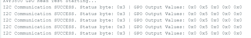
GPOピン状態の読み取り
目的: すべての**出力可能GPIO(GPO)**の論理レベルを確認します。 コードのハイライト:
- 以下を使用して読み取りリクエストを送信:
- リソースID: 20(GPO)
- コマンドID: 0(GPO_READ_VALUES)
- 5つのGPOピンの状態を順番に読み取り: X0D11 → X0D30 → X0D31 → X0D33 → X0D39
- レスポンスを検証するためのステータスバイトを含む
#include <Wire.h>

#define XMOS_ADDR 0x2C  // I2C 7-bit address

#define GPO_SERVICER_RESID 20
#define GPO_SERVICER_RESID_GPO_READ_VALUES 0
#define GPO_GPO_READ_NUM_BYTES 5

void setup() {
  Serial.begin(115200);
  while (!Serial);
  Wire.begin();
  delay(1000);
  Serial.println("XVF3800 GPO Read Test Starting...");
}

void loop() {
  uint8_t gpo_values[GPO_GPO_READ_NUM_BYTES] = {0};
  uint8_t status = 0xFF;

  bool success = read_gpo_values(gpo_values, &status);

  if (success) {
    Serial.print("I2C Communication SUCCESS. Status byte: 0x");
    Serial.print(status, HEX);
    Serial.print(" | GPO Output Values: ");
    for (uint8_t i = 0; i < GPO_GPO_READ_NUM_BYTES; i++) {
      Serial.print("0x");
      Serial.print(gpo_values[i], HEX);
      Serial.print(" ");
    }
    Serial.println();
  } else {
    Serial.println("Failed to read GPO values.");
  }

  delay(1000);
}

bool read_gpo_values(uint8_t *buffer, uint8_t *status) {
  const uint8_t resid = GPO_SERVICER_RESID;
  const uint8_t cmd = GPO_SERVICER_RESID_GPO_READ_VALUES | 0x80;
  const uint8_t read_len = GPO_GPO_READ_NUM_BYTES;

  // Step 1: Write command
  Wire.beginTransmission(XMOS_ADDR);
  Wire.write(resid);
  Wire.write(cmd);
  Wire.write(read_len + 1);
  uint8_t result = Wire.endTransmission();

  if (result != 0) {
    Serial.print("I2C Write Error: ");
    Serial.println(result);
    return false;
  }

  // Step 2: Read response (status + payload)
  Wire.requestFrom(XMOS_ADDR, (uint8_t)(read_len + 1));
  if (Wire.available() < read_len + 1) {
    Serial.println("I2C Read Error: Not enough data received.");
    return false;
  }

  *status = Wire.read();
  for (uint8_t i = 0; i < read_len; i++) {
    buffer[i] = Wire.read();
  }

  return true;
}
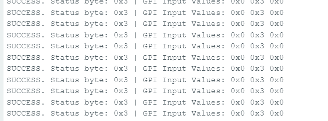
GPIピンの状態を読み取る
目標: 入力対応GPIOの状態を確認する(例:ミュートボタンの状態)。 コードのハイライト:
- 以下にコマンドを送信:
- リソースID: 36 (IO_CONFIG)
- コマンドID: 6 (GPI_VALUE_ALL)
- X1D09、X1D13、X1D34の状態を表す3つのGPIを受信
#include <Wire.h>

#define XMOS_ADDR 0x2C  // I2C 7-bit address of XVF3800

// Resource and command IDs for GPI
#define IO_CONFIG_SERVICER_RESID 36
#define IO_CONFIG_SERVICER_RESID_GPI_READ_VALUES 0
#define GPI_READ_NUM_BYTES 3   // From header: IO_CONFIG_SERVICER_RESID_GPI_READ_VALUES_NUM_VALUES

void setup() {
  Serial.begin(115200);
  while (!Serial);
  Wire.begin();
  delay(1000);
  Serial.println("XVF3800 GPI Read Test Starting...");
}

void loop() {
  uint8_t gpi_values[GPI_READ_NUM_BYTES] = {0};
  uint8_t status = 0xFF;

  bool success = read_gpi_values(gpi_values, &status);

  if (success) {
    Serial.print("I2C Communication SUCCESS. Status byte: 0x");
    Serial.print(status, HEX);
    Serial.print(" | GPI Input Values: ");
    for (uint8_t i = 0; i < GPI_READ_NUM_BYTES; i++) {
      Serial.print("0x");
      Serial.print(gpi_values[i], HEX);
      Serial.print(" ");
    }
    Serial.println();
  } else {
    Serial.println("Failed to read GPI values.");
  }

  delay(1000);
}

bool read_gpi_values(uint8_t *buffer, uint8_t *status) {
  const uint8_t resid = IO_CONFIG_SERVICER_RESID;
  const uint8_t cmd = IO_CONFIG_SERVICER_RESID_GPI_READ_VALUES | 0x80;  // Read command
  const uint8_t read_len = GPI_READ_NUM_BYTES;

  // Step 1: Send the command
  Wire.beginTransmission(XMOS_ADDR);
  Wire.write(resid);
  Wire.write(cmd);
  Wire.write(read_len + 1);  // +1 for status byte
  uint8_t result = Wire.endTransmission();

  if (result != 0) {
    Serial.print("I2C Write Error: ");
    Serial.println(result);
    return false;
  }

  // Step 2: Read response (status + payload)
  Wire.requestFrom(XMOS_ADDR, (uint8_t)(read_len + 1));
  if (Wire.available() < read_len + 1) {
    Serial.println("I2C Read Error: Not enough data received.");
    return false;
  }

  *status = Wire.read();  // first byte is status
  for (uint8_t i = 0; i < read_len; i++) {
    buffer[i] = Wire.read();
  }

  return true;
}
GPOピンへの書き込み – マイクミュートの例
目標: 出力GPIOを制御する、例えば、GPIO 30 (X0D30)を切り替えてマイクをミュートする。 コードのハイライト:
- 以下への書き込みコマンドを送信:
- リソースID: 20
- コマンドID: 1 (GPO_WRITE_VALUE)
- ペイロード: ピン番号、値
例: {30, 1} でミュート
便利な関数:
- muteMic() → GPIO 30をHIGHに設定してマイクをミュートし、赤色LEDを点灯
- unmuteMic() → GPIO 30をLOWに設定してマイクのミュートを解除し、LEDを消灯
#include <Wire.h>

// Define the 7-bit I2C address of the XVF3800 device
#define XMOS_ADDR 0x2C

// Define XVF3800 Resource and Command IDs
#define GPO_SERVICER_RESID 20                         // Resource ID for GPIO Output (GPO)
#define GPO_SERVICER_RESID_GPO_WRITE_VALUE 1          // Command ID to write value to GPIO
#define IO_CONFIG_SERVICER_RESID 36                   // Resource ID for IO Configuration
#define IO_CONFIG_SERVICER_RESID_GPI_VALUE_ALL 6      // Command ID to read all GPIO input values

void setup() {
  Wire.begin();                 // Initialize I2C communication
  Serial.begin(115200);        // Initialize serial communication for debugging
  delay(1000);                 // Short delay to allow device startup

  Serial.println("Muting Mic (Setting GPIO 30 HIGH)");
  muteMic();                   // Set GPIO 30 HIGH to mute microphone
  delay(5000);                 // Wait for 5 seconds

  Serial.println("Unmuting Mic (Setting GPIO 30 LOW)");
  unmuteMic();                 // Set GPIO 30 LOW to unmute microphone
  delay(3000);                 // Wait for 3 seconds

  Serial.println("Reading GPIO Status...");
  readGPIOStatus();            // Read and print the status of all GPIOs
}

void loop() {
  // Empty loop - no repeated actions for now
}

// Function to set GPIO 30 to a specific logic level (0 = LOW, 1 = HIGH)
void setGPIO30(uint8_t level) {
  uint8_t payload[2] = {30, level};  // Payload format: [GPIO index, value]
  xmos_write_bytes(GPO_SERVICER_RESID, GPO_SERVICER_RESID_GPO_WRITE_VALUE, payload, 2);

  Serial.print("Command Sent: GPIO 30 = ");
  Serial.println(level);
}

// Convenience function to mute the microphone (set GPIO 30 HIGH)
void muteMic() {
  setGPIO30(1);  // Logic HIGH to mute
}

// Convenience function to unmute the microphone (set GPIO 30 LOW)
void unmuteMic() {
  setGPIO30(0);  // Logic LOW to unmute
}

// Function to write a sequence of bytes over I2C to the XVF3800
void xmos_write_bytes(uint8_t resid, uint8_t cmd, uint8_t *value, uint8_t write_byte_num) {
  Wire.beginTransmission(XMOS_ADDR); // Begin I2C transmission to XVF3800
  Wire.write(resid);                 // Write the resource ID
  Wire.write(cmd);                   // Write the command ID
  Wire.write(write_byte_num);       // Write number of payload bytes
  for (uint8_t i = 0; i < write_byte_num; i++) {
    Wire.write(value[i]);           // Write each payload byte
  }
  Wire.endTransmission();           // End the I2C transmission
}

// Function to read the status of all GPIO inputs (32 bits) from XVF3800
void readGPIOStatus() {
  uint8_t buffer[4] = {0};  // Buffer to hold the 4-byte GPIO status response

  // --- Write phase: Send read request ---
  Wire.beginTransmission(XMOS_ADDR);                        // Begin I2C write transaction
  Wire.write(IO_CONFIG_SERVICER_RESID);                     // Write the resource ID for IO config
  Wire.write(IO_CONFIG_SERVICER_RESID_GPI_VALUE_ALL);       // Write the command ID to get all GPIO values
  Wire.write(1);                                             // Payload length (1 byte)
  Wire.endTransmission(false);                              // End transmission with repeated start (no stop)

  // --- Read phase: Read response from device ---
  Wire.requestFrom(XMOS_ADDR, 5); // Request 5 bytes: 1 status byte + 4 data bytes

  if (Wire.available() < 5) {
    Serial.println("Error: Not enough bytes received from XVF3800.");
    return;
  }

  uint8_t status = Wire.read();  // Read the status byte (should be 0 for success)

  // Read the 4-byte GPIO input status value
  for (int i = 0; i < 4; i++) {
    buffer[i] = Wire.read();
  }

  // Combine 4 bytes into a single 32-bit unsigned integer
  uint32_t gpio_status = ((uint32_t)buffer[3] << 24) |
                         ((uint32_t)buffer[2] << 16) |
                         ((uint32_t)buffer[1] << 8)  |
                         ((uint32_t)buffer[0]);

  Serial.print("GPIO Status Register = 0x");
  Serial.println(gpio_status, HEX);

  // Check and print the state of GPIO 30 specifically
  bool gpio30 = (gpio_status >> 30) & 0x01;
  Serial.print("GPIO 30 State: ");
  Serial.println(gpio30 ? "HIGH (Muted)" : "LOW (Unmuted)");
}
技術サポート & 製品ディスカッション
弊社製品をお選びいただき、ありがとうございます!お客様の製品体験を可能な限りスムーズにするため、さまざまなサポートを提供いたします。異なる好みやニーズに対応するため、複数のコミュニケーションチャネルをご用意しております。