XIAO ESP32S3(Sense) With FreeRTOS
このwikiはSeeed Studio XIAO ESP32S3のFreeRTOSサポートについて説明します。このガイドの支援により、ボードで利用可能な機能セットを活用できるようになります。
FreeRTOSとは

FreeRTOSは、リアルタイムカーネルと補完的な機能を実装するモジュラーライブラリのセットで構成されるCライブラリのコレクションです。FreeRTOSカーネルは、FreeRTOS上に構築されたアプリケーションがハードリアルタイム要件を満たすことを可能にするリアルタイムカーネル(またはリアルタイムスケジューラ)です。これにより、アプリケーションを独立した実行スレッドのコレクションとして整理することができます。
参考:Mastering the FreeRTOS Real Time Kernel
FreeRTOSポート
FreeRTOSは、ESP-IDFにコンポーネントとして統合されたオープンソースRTOS(リアルタイムオペレーティングシステム)カーネルです。したがって、すべてのESP-IDFアプリケーションと多くのESP-IDFコンポーネントはFreeRTOSベースで書かれています。FreeRTOSカーネルは、ESPチップで利用可能なすべてのアーキテクチャ(すなわち、XtensaとRISC-V)にポートされています。
私たちはFreeRTOSのESP IDFポートを使用します。
ハードウェア準備
私はSeed Studio XIAO ESP32S3 Senseと、オンボードカメラ、マイクロフォン、SDカードリーダー、そしてESP32S3のWifi機能を使用しています。
| Seeed Studio XIAO ESP32S3(Sense) |
|---|
 |
追加コンポーネント
- Grove - Expansion Board - I2Cディスプレイ RTC & ボタン
- Air Quality Sensor v1.3
- Grove - Temperature, Humidity, Pressure and Gas Sensor for Arduino - BME680
- Acrylic Case for Seeed Studio XIAO Expansion board
ソフトウェア準備
私はESP-IDFを使用したVisual Studio Code(Windows)を使用しています。
- VSCodeインストール
- ESP-IDFインストールガイド
- Gitリポジトリ
| VS Code | ESP-IDF for VSCode |
|---|---|
入門ガイド
ESP-IDFのセットアップ
Visual Studio Extensionをセットアップした後、ターミナルを開き、以下のコマンドを貼り付けて、通常のターミナル環境(VScode外)からESP-IDFコマンドラインツールにアクセスします。
VS-CodeのESP-IDF拡張機能の通常のインストールは90%のユースケースに対応します。環境外でESPコマンドラインツールが必要な場合のみ、以下の手順を実行してください。
PowerShell(Windows)
.$HOME\esp\v5.3\esp-idf\export.ps1
".$HOME\esp\v5.3\esp-idf"はユーザーによって異なる場合があります。これはデフォルトのインストールパスです。
お使いのデバイスのインストールパスに置き換えてください。
繰り返しセットアップを避けるために、管理者モードでPowerShellを起動し、以下のコマンドを入力してください
notepad $PSHOME\Profile.ps1
メモ帳のインスタンスが開きます。メモ帳にexportシェルコマンドを貼り付けて保存してください。 powershellのインスタンスを開くと、以下のような出力が表示されるはずです。
Done! You can now compile ESP-IDF projects.
すべてが適切に実行されている場合、以下のコマンド:
idf.py
は以下の出力を表示するはずです:
Usage: idf.py [OPTIONS] COMMAND1 [ARGS]... [COMMAND2 [ARGS]...]...

  ESP-IDF CLI build management tool. For commands that are not known to idf.py an attempt to execute it as a build
  system target will be made. Selected target: None
XIAO ESP32S3のボード設定
ESP-IDFをセットアップした後、8MB FlashおよびOctal PSRAMを含むハードウェア機能を活用するために、XIAO ESP32S3ボード専用にプロジェクトを設定する必要があります。
ターゲットデバイスの設定
ESP-IDFプロジェクトディレクトリで、ターゲットをESP32-S3に設定します:
idf.py set-target esp32s3
フルビルドオプションの有効化
プロジェクトのルートCMakeLists.txtで、MINIMAL_BUILDがOFFに設定されていることを確認してください:
idf_build_set_property(MINIMAL_BUILD OFF)
これにより、menuconfigですべての設定オプションが有効になります。
FlashとPSRAMの設定
設定メニューを開きます:
idf.py menuconfig
Flashサイズ設定:
- 移動先:Serial flasher config → Flash size
- 設定:8 MB
PSRAM設定:
- 移動先:Component config → ESP PSRAM
- 有効化:Support for external, SPI-connected RAM
- SPI RAM modeを設定:Octal Mode PSRAM
- SPI RAM clockを設定:80MHz
XIAO ESP32S3はOctal PSRAMを使用しており、Quadモードではありません。8MB PSRAMが適切に機能するためには、正しいモードを選択することが重要です。
メインコンポーネント依存関係の更新
/main/CMakeLists.txtで、PSRAMとSPIフラッシュコンポーネントが含まれていることを確認してください:
idf_component_register(
    SRCS "main.c"
    INCLUDE_DIRS "."
    PRIV_REQUIRES esp_psram spi_flash
)
ボードピン設定コンポーネントの作成
コードをより読みやすく、ポータブルにするために、XIAOピン定義の再利用可能なコンポーネントを作成します:
mkdir -p ./components/board_config/include/
./components/board_config/include/xiao_pins.hを作成:
// xiao_pins.h
#pragma once

#ifdef __cplusplus
extern "C" {
#endif

// Analog / Digital Pins
#define XIAO_D0     1
#define XIAO_D1     2
#define XIAO_D2     3
#define XIAO_D3     4
#define XIAO_D4     5
#define XIAO_D5     6
#define XIAO_D6     43
#define XIAO_D7     44
#define XIAO_D8     7
#define XIAO_D9     8
#define XIAO_D10    9

// Onboard User LED (Active Low)
#define XIAO_LED    21

// I2C Pins (Default)
#define XIAO_SDA    5   // Same as D4
#define XIAO_SCL    6   // Same as D5

// SPI Pins (Default)
#define XIAO_MISO   9   // Same as D10
#define XIAO_MOSI   10
#define XIAO_SCK    8   // Same as D9
#define XIAO_SS     7   // Same as D8

#ifdef __cplusplus
}
#endif
./components/board_config/CMakeLists.txtを作成:
idf_component_register(INCLUDE_DIRS "include")
これらのピン定義はXIAO ESP32S3ボード上のシルクスクリーンラベルと一致しており、コードをより読みやすくします。例えば、GPIO 21をハードコーディングする代わりにXIAO_LEDを使用してください。
コード内でのピン定義の使用
メインアプリケーションまたは任意のコンポーネントで、ヘッダーをインクルードします:
#include "xiao_pins.h"

void app_main(void) {
    // Example: Configure LED pin
    gpio_set_direction(XIAO_LED, GPIO_MODE_OUTPUT);
    gpio_set_level(XIAO_LED, 0);  // Turn on (active low)
}
ピンマッピングリファレンス
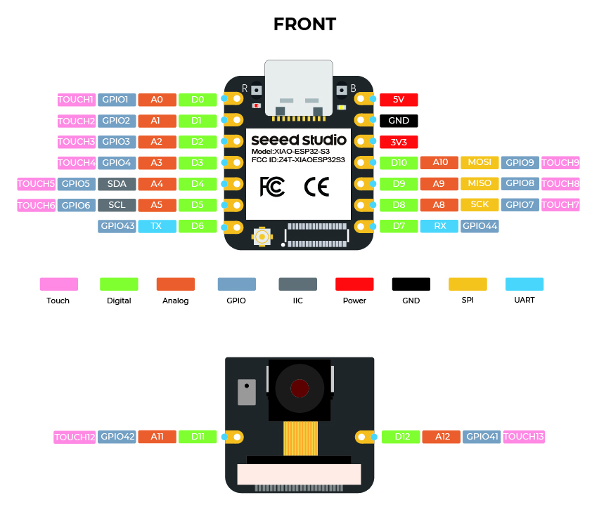
| ラベル | GPIO | 代替機能 |
|---|---|---|
| D0 | 1 | ADC1_CH0 |
| D1 | 2 | ADC1_CH1 |
| D2 | 3 | ADC1_CH2 |
| D3 | 4 | ADC1_CH3 |
| D4 | 5 | ADC1_CH4, SDA |
| D5 | 6 | ADC1_CH5, SCL |
| D6 | 43 | TX |
| D7 | 44 | RX |
| D8 | 7 | ADC1_CH6, SS |
| D9 | 8 | ADC1_CH7, SCK |
| D10 | 9 | ADC1_CH8, MISO |
- GPIO 19と20はUSB D-/D+に使用されており、再設定すべきではありません
- GPIO 21のオンボードLEDはアクティブLOW(点灯するには0に設定)です
- すべてのピンD0-D10はADC1を介してアナログ入力をサポートします
ビルドとフラッシュ
プロジェクトをビルドします:
idf.py build
XIAO ESP32-S3にフラッシュします:
idf.py -p /dev/ttyACM0 flash monitor
/dev/ttyACM0を実際のシリアルポートに置き換えてください(Windowsでは通常COM3、COM4など)。
ボード設定のトラブルシューティング
PSRAMが検出されない:
- Octalモードが選択されていることを確認(Quadではない)
- フラッシュサイズが8MBに設定されていることを確認
- ESP-IDFバージョンが4.4以降であることを確認
アップロードが失敗する:
- USB接続中にBOOTボタンを押し続ける
- アップロード速度を下げてみる:
idf.py -p PORT -b 115200 flash
ピンの競合:
- GPIOピン19と20(USB D-とD+)の使用を避ける
- XIAO_LED(GPIO 21)はオンボードLEDと共有されています
タスクとは?
タスクは、プロセッサが設定のセットで実行を要求される小さな関数/ジョブです。タスクは小さな関数から無限ループ関数まで様々です。 タスクは ESP-IDF アプリケーションにおける実行の基本単位です。これらは本質的に他のタスクと同時に実行される関数です。これにより効率的なマルチタスクと応答性が可能になります。
タスクプロパティとは?
このトピックの広範囲性により、このガイドで使用するプロパティのいくつかのみを取り上げます。
- TaskFunction: これはタスクの実際のロジックを含む関数です。タスクの実行のエントリーポイントです。
- StackSize: これはタスクのスタックに割り当てられるメモリ量を指定します。スタックはローカル変数、関数の戻りアドレス、一時データを格納するために使用されます。
- TaskPriority: これは他のタスクと比較したタスクの相対的な重要度を決定します。優先度の高いタスクは優先度の低いタスクより先に実行される可能性が高くなります。
- TaskParameters: これらはタスクが作成される際にタスク関数に渡すことができるオプションの引数です。タスクに追加のコンテキストや設定を提供するために使用できます。
- CoreAffinity: これはタスクが割り当てられるべき CPU コアを指定します。複数のコアを持つシステムでは、これはパフォーマンスを最適化したり、ワークロードのバランスを取るために使用できます。
タスクの作成
FreeRTOS でタスクを作成するには、xTaskCreate 関数を使用します。この関数はタスク関数、タスク名、スタックサイズ、パラメータ、優先度、作成されたタスクへのハンドルを含むいくつかのパラメータを取ります。
TaskHandle_t task;
xTaskCreate(
        taskFunction,             /* Function that implements the task. */
        "taskName",               /* Text name for the task. */
        configMINIMAL_STACK_SIZE, /* Stack size in words, or bytes. */
        NULL,                     /* Parameter passed into the task. */
        tskIDLE_PRIORITY,         /* Priority at which the task is created. */
        &task                     /* Used to pass out the created task's handle. */
        );
コアに固定されたタスクの作成
タスクを作成して特定のコアに固定するには(使用中のチップがデュアルコアの場合のみ)、xTaskCreatePinnedToCore 関数を使用します。この関数は xTaskCreate と似ていますが、コアを指定するための追加パラメータが含まれています。
TaskHandle_t task;
xTaskCreatePinnedToCore(
        taskFunction,             /* Function that implements the task. */
        "taskName",               /* Text name for the task. */
        configMINIMAL_STACK_SIZE, /* Stack size in words, or bytes. */
        NULL,                     /* Parameter passed into the task. */
        tskIDLE_PRIORITY,         /* Priority at which the task is created. */
        &task,                    /* Used to pass out the created task's handle. */
        0);                       /* Core ID */
タスク関数の呼び出し
タスク関数は、タスクによって実行される実際のコードです。
void taskFunction(void * pvParameters) {
  /*
  Function definition goes here
  */
}
タスクの可視化
FreeRTOS の動作を可視化するために、4つの簡単なタスクを作成しています。
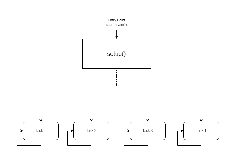
視覚的表現
CPU0
-----
taskFunction1 (1000ms delay)

CPU1
-----
taskFunction2 (500ms delay)
taskFunction3 (500ms delay)
taskFunction4 (500ms delay)
コード
#include <stdio.h>
#include "freertos/FreeRTOS.h"
#include "freertos/task.h"
#include "sdkconfig.h"
#include "esp_log.h"

TaskHandle_t task1,task2,task3,task4;

void taskFunction1(void * pvParameters) {
    while (true) {
        ESP_LOGI("Task1", "Hello from task 1");
        vTaskDelay(pdMS_TO_TICKS(1000)); // Add a delay to avoid overwhelming the output
    }
}

void taskFunction2(void * pvParameters) {
    while (true) {
        ESP_LOGI("Task2", "Hello from task 2");
        vTaskDelay(pdMS_TO_TICKS(500)); // Add a delay to avoid overwhelming the output
    }
}

void taskFunction3(void * pvParameters) {
    while (true) {
        ESP_LOGI("Task3", "Hello from task 3");
        vTaskDelay(pdMS_TO_TICKS(500)); // Add a delay to avoid overwhelming the output
    }
}

void taskFunction4(void * pvParameters) {
    while (true) {
        ESP_LOGI("Task4", "Hello from task 4");
        vTaskDelay(pdMS_TO_TICKS(500)); // Add a delay to avoid overwhelming the output
    }
}

void app_main(void) {
    xTaskCreatePinnedToCore(
        taskFunction1, /* Function that implements the task. */
        "task_1",        /* Text name for the task. */
        configMINIMAL_STACK_SIZE, /* Stack size in words, not bytes. */
        NULL,            /* Parameter passed into the task. */
        tskIDLE_PRIORITY, /* Priority at which the task is created. */
        &task1,         /* Used to pass out the created task's handle. */
        0);              /* Core ID */

    xTaskCreatePinnedToCore(
        taskFunction2, /* Function that implements the task. */
        "task_2",        /* Text name for the task. */
        configMINIMAL_STACK_SIZE, /* Stack size in words, not bytes. */
        NULL,            /* Parameter passed into the task. */
        tskIDLE_PRIORITY, /* Priority at which the task is created. */
        &task2,         /* Used to pass out the created task's handle. */
        1);              /* Core ID */

    xTaskCreatePinnedToCore(
        taskFunction3, /* Function that implements the task. */
        "task_3",        /* Text name for the task. */
        configMINIMAL_STACK_SIZE, /* Stack size in words, not bytes. */
        NULL,            /* Parameter passed into the task. */
        tskIDLE_PRIORITY, /* Priority at which the task is created. */
        &task3,         /* Used to pass out the created task's handle. */
        1);              /* Core ID */

    xTaskCreatePinnedToCore(
        taskFunction4, /* Function that implements the task. */
        "task_4",        /* Text name for the task. */
        configMINIMAL_STACK_SIZE, /* Stack size in words, not bytes. */
        NULL,            /* Parameter passed into the task. */
        tskIDLE_PRIORITY, /* Priority at which the task is created. */
        &task4,         /* Used to pass out the created task's handle. */
        1);              /* Core ID */
}
configMINIMAL_STACK_SIZE は sdkconfig で変更できます。
- 4つのタスク: コードは4つのタスクを定義します:taskFunction1、taskFunction2、taskFunction3、taskFunction4。
- タスク優先度: すべてのタスクは tskIDLE_PRIORITY で作成されます。これは同じ優先度を持つことを意味します。
- タスク固定: taskFunction1 は CPU0 に固定され、他の3つのタスクは CPU1 に固定されます。
- タスク遅延: taskFunction1 は 1000ms の遅延を持ち、他の3つは 500ms の遅延を持ちます。
CPU0 と CPU1 のタスクスケジュールの作成
CPU0 と CPU1 の基本的なタスクスケジュールを作成しました。
CPU0 タスクスケジュール
Task: taskFunction1
Priority: Idle (lowest)
Delay: 1000ms
Core: 0
CPU1 タスクスケジュール
Tasks: taskFunction2, taskFunction3, taskFunction4
Priorities: All Idle (same priority)
Delays: 500ms for all tasks
Core: 1
これは簡略化されたスケジュールです。リアルタイムシステムでの実際のタスクスケジューリングには、タスク優先度、デッドライン、リソース制約などのより複雑な要因が関わります。
出力
I (11412) Task1: Hello from task 1
I (11522) Task3: Hello from task 3
I (11522) Task2: Hello from task 2
I (11532) Task4: Hello from task 4
I (12032) Task3: Hello from task 3
I (12032) Task2: Hello from task 2
I (12042) Task4: Hello from task 4
I (12422) Task1: Hello from task 1
I (12542) Task3: Hello from task 3
I (12542) Task2: Hello from task 2
I (12552) Task4: Hello from task 4
I (13052) Task3: Hello from task 3
I (13052) Task2: Hello from task 2
I (13062) Task4: Hello from task 4
I (13432) Task1: Hello from task 1
I (13562) Task3: Hello from task 3
I (13562) Task2: Hello from task 2
I (13572) Task4: Hello from task 4
I (14072) Task3: Hello from task 3
I (14072) Task2: Hello from task 2
I (14082) Task4: Hello from task 4
FreeRTOS を使用したセンサーポーリング
これには、ESP_IDF_v5.3 と共にアナログセンサー Air Quality Sensor v1.3 を使用しています。
ハードウェアセットアップ
Xiao-S3 を Grove - Expansion Board に取り付け、Air Quality Sensor v1.3 をアナログコネクタに接続します。
ソフトウェアセットアップ
gitリポジトリをプルした後、VSCodeでフォルダを開きます。View->Command Palette->ESP-IDF: Add vscode Configuration Folderに移動します。 下部パネルから正しいCOMポート、チップ(ESP-S3)を選択し、ビルド、フラッシュ、モニターを実行します。
コード概要
このコードは、センサーから空気品質データを収集し、生データを処理して空気品質レベルを決定し、定期的に結果をコンソールに出力するように設計されています。
主要コンポーネント
- センサー初期化:
air_quality_sensor_t air_quality_sensor;

void sensor_setup()
{
    air_quality_sensor._io_num = ADC_CHANNEL_0;
    air_quality_sensor._adc_num = ADC_UNIT_1;
    printf("Starting Air Quality Sensor...\n");
    if(!initialize_air_quality_sensor(&air_quality_sensor))
    {
        printf("Sensor ready.\n");
    }
    else{
        printf("Sensor ERROR!\n");
    }
}
-
sensor_setup()関数は、センサーのI/Oピンとユニットを設定します。
-
initialize_air_quality_sensor()を使用してセンサーの初期化を試行します。
-
初期化が成功すると、センサーはデータ収集の準備が整います。
-
データ収集タスク:
void poll_read_air_quality_sensor(void *pvParameters)
{
    for (;;)
    {
        air_quality_sensor_slope(&air_quality_sensor);
        vTaskDelay(500 / portTICK_PERIOD_MS);
    }
}
-
poll_read_air_quality_sensor()タスクは、センサーから生データを継続的に読み取るために作成されます。
-
air_quality_sensor_slope()を呼び出して生データを処理し、空気品質の指標である傾きを計算します。
-
タスクは次のデータポイントを読み取る前に500ミリ秒遅延します。
-
データ出力タスク:
void print_read_air_quality_sensor(void *pvParameters)
{
    for (;;)
    {
        char buf[40];
        air_quality_error_to_message(air_quality_sensor._air_quality,buf);
        printf("Time : %lu\tSlope : %d\tRaw Value : %d\n%s\n", (uint32_t)esp_timer_get_time() / 1000, air_quality_sensor._air_quality, air_quality_sensor._sensor_raw_value,buf);
        vTaskDelay(1000 / portTICK_PERIOD_MS);
    }
}
- print_read_air_quality_sensor()タスクは、収集されたデータと計算された空気品質を定期的に出力するために作成されます。
- air_quality_error_to_message()を使用して現在の時刻、傾き、生の値、空気品質メッセージを取得します。
- タスクはフォーマットされた形式でデータをコンソールに出力します。
- タスクは次のデータポイントを出力する前に1000ミリ秒遅延します。
void app_main(void)
{
    sensor_setup();
    xTaskCreatePinnedToCore(
        poll_read_air_quality_sensor,   /* Function that implements the task. */
        "poll_read_air_quality_sensor", /* Text name for the task. */
        configMINIMAL_STACK_SIZE * 2,   /* Stack size in words, not bytes. */
        NULL,                           /* Parameter passed into the task. */
        tskIDLE_PRIORITY,               /* Priority at which the task is created. */
        NULL,                           /* Used to pass out the created task's handle. */
        0);                             /* Core ID */

    xTaskCreatePinnedToCore(
        print_read_air_quality_sensor,   /* Function that implements the task. */
        "print_read_air_quality_sensor", /* Text name for the task. */
        configMINIMAL_STACK_SIZE * 2,    /* Stack size in words, not bytes. */
        NULL,                            /* Parameter passed into the task. */
        tskIDLE_PRIORITY + 1,            /* Priority at which the task is created. */
        NULL,                            /* Used to pass out the created task's handle. */
        0);                              /* Core ID */
}
出力
Time : 37207    Slope : 3       Raw Value : 273
Fresh air.
Time : 38217    Slope : 3       Raw Value : 269
Fresh air.
Time : 39227    Slope : 3       Raw Value : 274
Fresh air.
Time : 40237    Slope : 3       Raw Value : 251
Fresh air.
Time : 41247    Slope : 3       Raw Value : 276
Fresh air.
Time : 42257    Slope : 3       Raw Value : 250
Fresh air.
Time : 43267    Slope : 3       Raw Value : 236
Fresh air.
Time : 44277    Slope : 3       Raw Value : 253
Fresh air.
Time : 45287    Slope : 3       Raw Value : 245
Fresh air.
Time : 46297    Slope : 3       Raw Value : 249
Fresh air.
Time : 47307    Slope : 3       Raw Value : 244
Fresh air.
Time : 48317    Slope : 3       Raw Value : 235
Fresh air.
Time : 49327    Slope : 3       Raw Value : 239
Fresh air.
Time : 50337    Slope : 3       Raw Value : 233
Fresh air.
Time : 51347    Slope : 3       Raw Value : 235
Fresh air.
FreeRTOSでのカメラとSDカードの使用
これには、ESP_IDF_v5.3と共にオンボードカメラとSDカードを使用しています。
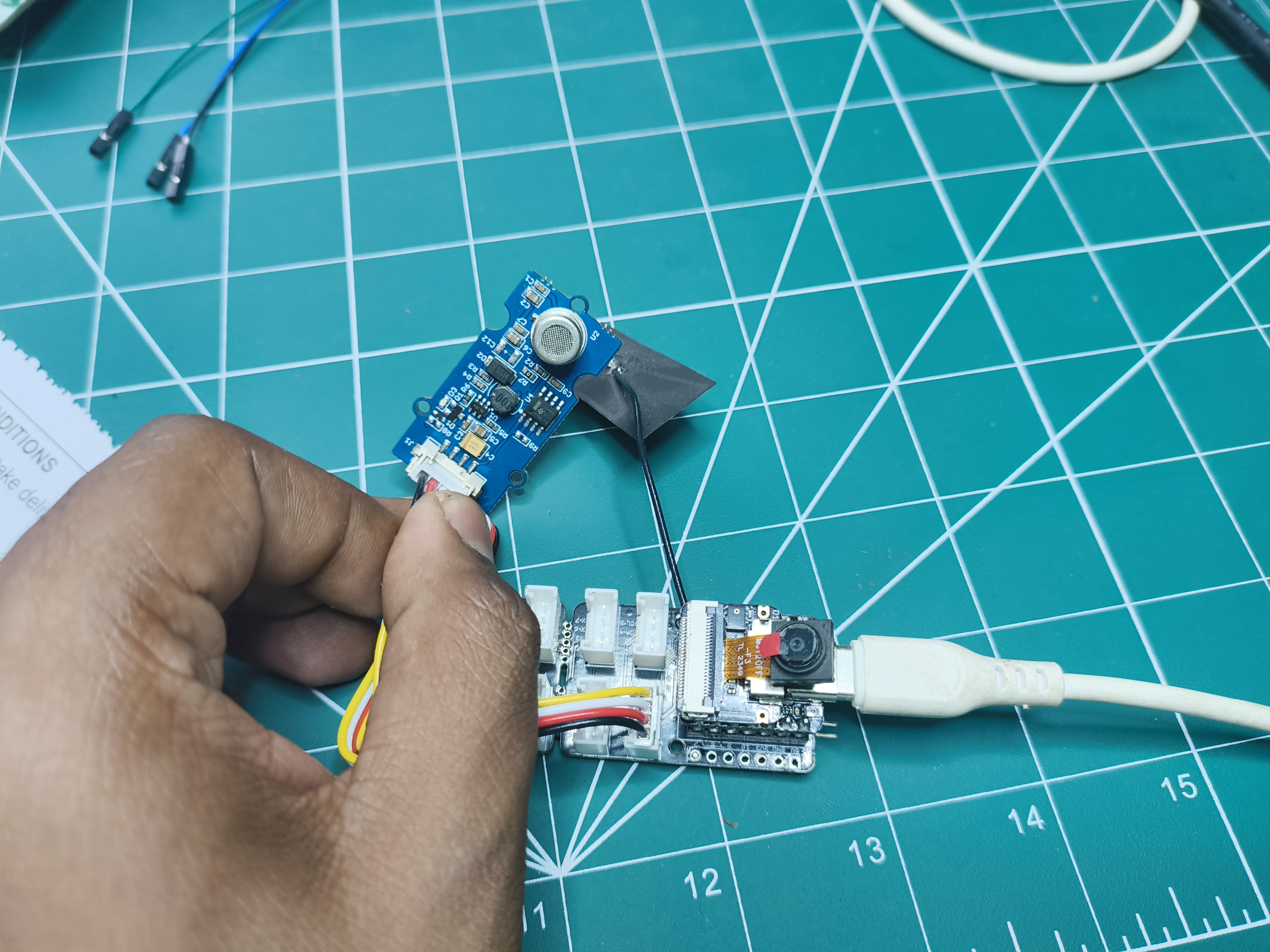
ハードウェアセットアップ
microSDカードガイドとカメラガイドに従って、カメラとmicroSDカード拡張ボードを取り付けます
- microSDカードをフォーマット(最大32GBまでサポート)
- microSDカードを拡張ボードに取り付け
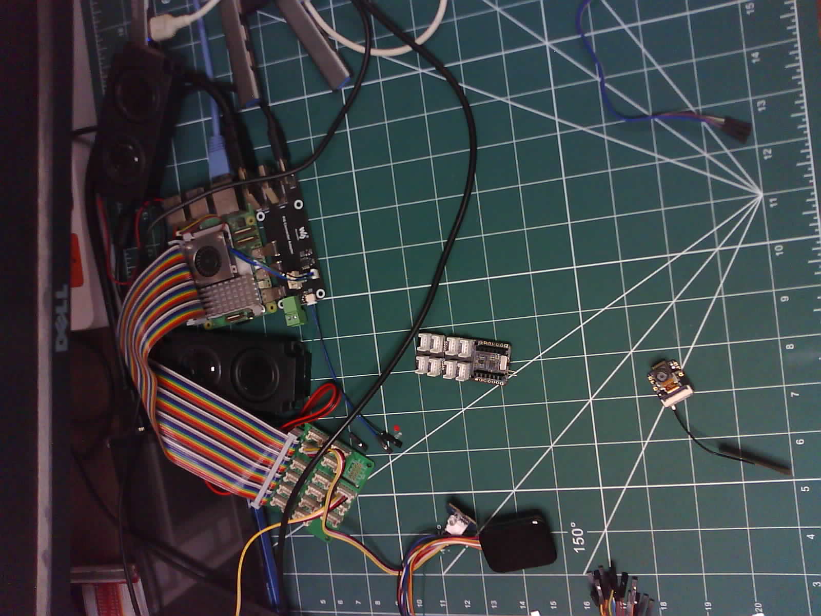
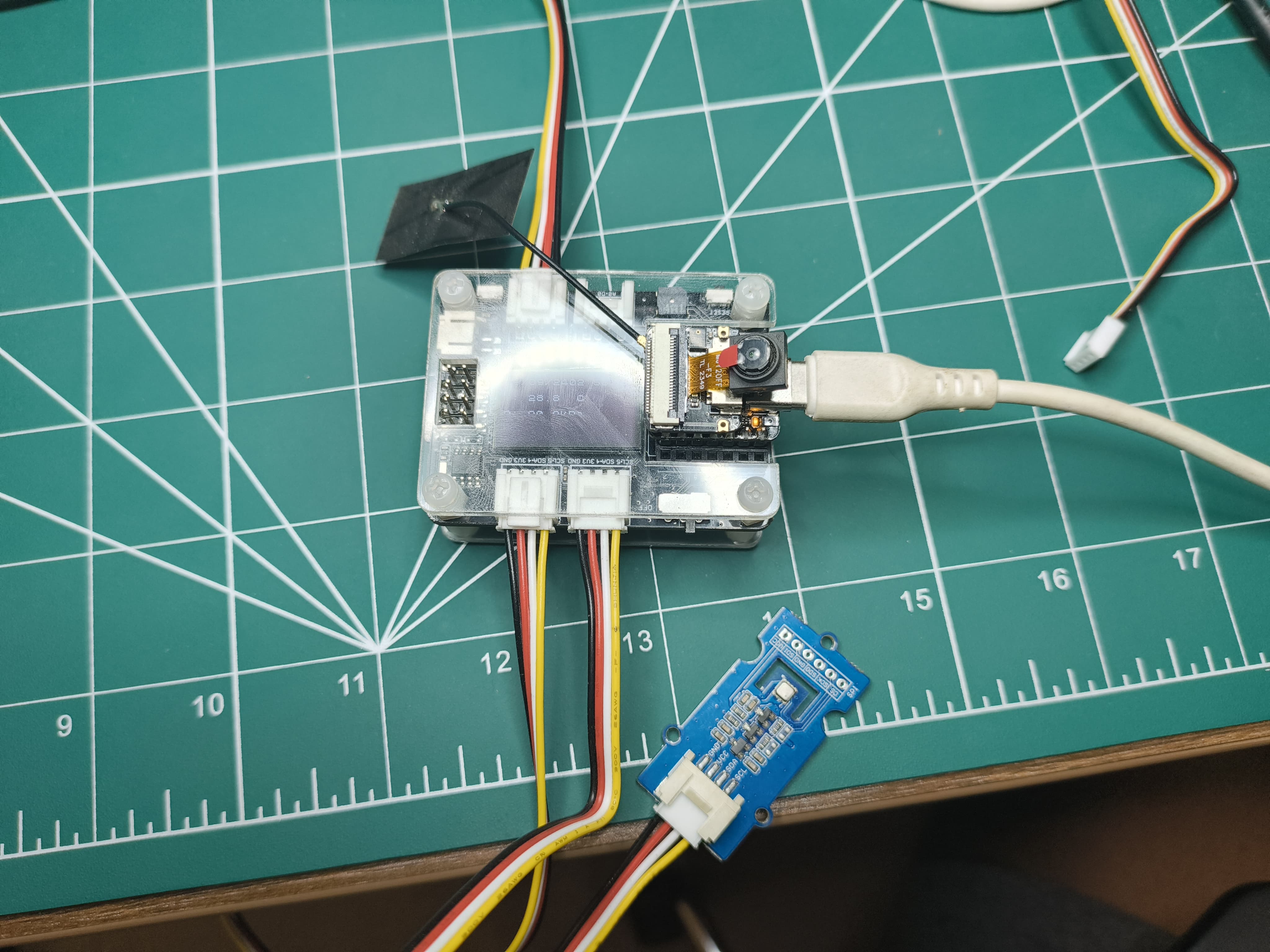
セットアップは次のようになります:
| 前面 | 背面 |
|---|---|
 |  |
ソフトウェアセットアップ
gitリポジトリをプルした後、VSCodeでフォルダを開きます。View->Command Palette->ESP-IDF: Add vscode Configuration Folderに移動します。 下部パネルから正しいCOMポート、チップ(ESP-S3)を選択し、ビルド、フラッシュ、モニターを実行します。
OV3660モデルを使用している場合、それを駆動できるようにIDFで設定する必要があります。ターミナルで**"idf.py menuconfig"**を入力してください
| ステップ1 | ステップ2 | ステップ3 |
|---|---|---|
 |  |  |
カメラコンポーネント
- カメラ設定:
- 様々なカメラ機能に使用されるGPIOピンを定義(PWDN、RESET、XCLK、SIOD、SIOC、Y9-Y2、VSYNC、HREF、PCLK、LED)。
- カメラパラメータのデフォルト値を設定(例:クロック周波数、フレームバッファ位置、ピクセル形式、フレームサイズ、JPEG品質、フレームバッファ数、グラブモード)。
#ifndef CAMERA_CONFIG_H
#define CAMERA_CONFIG_H

#define PWDN_GPIO_NUM     -1
#define RESET_GPIO_NUM    -1
#define XCLK_GPIO_NUM     10
#define SIOD_GPIO_NUM     40
#define SIOC_GPIO_NUM     39

#define Y9_GPIO_NUM       48
#define Y8_GPIO_NUM       11
#define Y7_GPIO_NUM       12
#define Y6_GPIO_NUM       14
#define Y5_GPIO_NUM       16
#define Y4_GPIO_NUM       18
#define Y3_GPIO_NUM       17
#define Y2_GPIO_NUM       15
#define VSYNC_GPIO_NUM    38
#define HREF_GPIO_NUM     47
#define PCLK_GPIO_NUM     13

#define LED_GPIO_NUM      21

#endif //CAMERA_CONFIG_H
-
カメラインターフェース:
initialize_camera()とcreateCameraTask()関数を宣言します。 -
カメラ実装:
- 定義された設定を使用してカメラを初期化します。
void initialize_camera(void)
{
  camera_config_t camera_config = {
      .pin_pwdn = PWDN_GPIO_NUM,
      .pin_reset = RESET_GPIO_NUM,
      .pin_xclk = XCLK_GPIO_NUM,
      .pin_sccb_sda = SIOD_GPIO_NUM,
      .pin_sccb_scl = SIOC_GPIO_NUM,
      .pin_d7 = Y9_GPIO_NUM,
      .pin_d6 = Y8_GPIO_NUM,
      .pin_d5 = Y7_GPIO_NUM,
      .pin_d4 = Y6_GPIO_NUM,
      .pin_d3 = Y5_GPIO_NUM,
      .pin_d2 = Y4_GPIO_NUM,
      .pin_d1 = Y3_GPIO_NUM,
      .pin_d0 = Y2_GPIO_NUM,
      .pin_vsync = VSYNC_GPIO_NUM,
      .pin_href = HREF_GPIO_NUM,
      .pin_pclk = PCLK_GPIO_NUM,

      .xclk_freq_hz = 20000000,          // The clock frequency of the image sensor
      .fb_location = CAMERA_FB_IN_PSRAM, // Set the frame buffer storage location
      .pixel_format = PIXFORMAT_JPEG,    // The pixel format of the image: PIXFORMAT_ + YUV422|GRAYSCALE|RGB565|JPEG
      .frame_size = FRAMESIZE_UXGA,      // The resolution size of the image: FRAMESIZE_ + QVGA|CIF|VGA|SVGA|XGA|SXGA|UXGA
      .jpeg_quality = 15,                // The quality of the JPEG image, ranging from 0 to 63.
      .fb_count = 2,                     // The number of frame buffers to use.
      .grab_mode = CAMERA_GRAB_LATEST    //  The image capture mode.
  };

  esp_err_t ret = esp_camera_init(&camera_config);
  if (ret == ESP_OK)
  {
      ESP_LOGI(cameraTag, "Camera configured successful");
  }
  else
  {
      ESP_LOGI(cameraTag, "Camera configured unsuccessful");
      return;
  }
}- カメラパラメータ(明度、コントラスト、彩度、特殊効果、ホワイトバランス、露出制御、AEC、AEレベル、AEC値、ゲイン制御、AGCゲイン、ゲイン上限、BPC、WPC、raw GMA、LENC、hmirror、vflip、DCW、colorbar)を設定します。
sensor_t *s = esp_camera_sensor_get();

  s->set_brightness(s, 0);                 // -2 to 2
  s->set_contrast(s, 0);                   // -2 to 2
  s->set_saturation(s, 0);                 // -2 to 2
  s->set_special_effect(s, 0);             // 0 to 6 (0 - No Effect, 1 - Negative, 2 - Grayscale, 3 - Red Tint, 4 - Green Tint, 5 - Blue Tint, 6 - Sepia)
  s->set_whitebal(s, 1);                   // 0 = disable , 1 = enable
  s->set_awb_gain(s, 1);                   // 0 = disable , 1 = enable
  s->set_wb_mode(s, 0);                    // 0 to 4 - if awb_gain enabled (0 - Auto, 1 - Sunny, 2 - Cloudy, 3 - Office, 4 - Home)
  s->set_exposure_ctrl(s, 1);              // 0 = disable , 1 = enable
  s->set_aec2(s, 0);                       // 0 = disable , 1 = enable
  s->set_ae_level(s, 0);                   // -2 to 2
  s->set_aec_value(s, 300);                // 0 to 1200
  s->set_gain_ctrl(s, 1);                  // 0 = disable , 1 = enable
  s->set_agc_gain(s, 0);                   // 0 to 30
  s->set_gainceiling(s, (gainceiling_t)0); // 0 to 6
  s->set_bpc(s, 0);                        // 0 = disable , 1 = enable
  s->set_wpc(s, 1);                        // 0 = disable , 1 = enable
  s->set_raw_gma(s, 1);                    // 0 = disable , 1 = enable
  s->set_lenc(s, 1);                       // 0 = disable , 1 = enable
  s->set_hmirror(s, 0);                    // 0 = disable , 1 = enable
  s->set_vflip(s, 0);                      // 0 = disable , 1 = enable
  s->set_dcw(s, 1);                        // 0 = disable , 1 = enable
s->set_colorbar(s, 0); // 0 = disable , 1 = enable- 画像をキャプチャしてSDカードに保存するtakePicture()関数を定義します。
void takePicture()
{
  ESP_LOGI(cameraTag, "Taking picture...");
  camera_fb_t *pic = esp_camera_fb_get();

  if (pic)
  {
      saveJpegToSdcard(pic);
  }

  ESP_LOGI(cameraTag, "Picture taken! Its size was: %zu bytes", pic->len);

  esp_camera_fb_return(pic);
}- 5秒ごとに継続的に写真を撮影するタスクcameraTakePicture_5_sec()を作成します。
void cameraTakePicture_5_sec(void *pvParameters)
{
    for (;;)
    {
        takePicture();
        vTaskDelay(5000 / portTICK_PERIOD_MS);
    }
}

void createCameraTask()
{
    TaskHandle_t task;
    xTaskCreate(
        cameraTakePicture_5_sec,      /* Function that implements the task. */
        "cameraTakePicture_5_sec",    /* Text name for the task. */
        configMINIMAL_STACK_SIZE * 4, /* Stack size in words, or bytes. */
        NULL,                         /* Parameter passed into the task. */
        tskIDLE_PRIORITY,             /* Priority at which the task is created. */
        &task                         /* Used to pass out the created task's handle. */
    );
}
コード構造:
- ヘッダーファイル(camera_config.h、camera_interface.h)と実装ファイル(camera_interface.c)。
- camera_config.hファイルはカメラ設定パラメータを定義します。
- camera_interface.hファイルはカメラ初期化とタスク作成の関数を宣言します。
- camera_interface.cファイルはカメラ初期化、写真撮影、タスク作成のロジックを実装します。
SdCardコンポーネント
- SDカード設定:
SDカードインターフェースに使用されるGPIOピン(MISO、MOSI、CLK、CS)を定義します。
#ifndef SDCARD_CONFIG_H
#define SDCARD_CONFIG_H

#define PIN_NUM_MISO  GPIO_NUM_8
#define PIN_NUM_MOSI  GPIO_NUM_9
#define PIN_NUM_CLK   GPIO_NUM_7
#define PIN_NUM_CS    GPIO_NUM_21

#endif //SDCARD_CONFIG_H
- SDカードインターフェース:
initialize_sdcard()、deinitialize_sdcard()、saveJpegToSdcard()関数を宣言します。
#ifndef SDCARD_INTERFACE_H
#define SDCARD_INTERFACE_H

#include "esp_camera.h"

void initialize_sdcard(void);
void deinitialize_sdcard();
void saveJpegToSdcard(camera_fb_t *);

#endif //SDCARD_INTERFACE_H
-
SDカード実装:
- 定義された設定を使用してSDカードを初期化し、SDカードをFATファイルシステムとしてマウントします。
sdmmc_card_t *card;
sdmmc_host_t host = SDSPI_HOST_DEFAULT();
const char mount_point[] = "/sd";

void initialize_sdcard()
{
    esp_err_t ret;

    // If format_if_mount_failed is set to true, SD card will be partitioned and
    // formatted in case when mounting fails.
    esp_vfs_fat_sdmmc_mount_config_t mount_config = {
#ifdef FORMAT_IF_MOUNT_FAILED
        .format_if_mount_failed = true,
#else
        .format_if_mount_failed = false,
#endif // EXAMPLE_FORMAT_IF_MOUNT_FAILED
        .max_files = 5,
        .allocation_unit_size = 32 * 1024};

    ESP_LOGI(sdcardTag, "Initializing SD card");

    // Use settings defined above to initialize SD card and mount FAT filesystem.
    // Note: esp_vfs_fat_sdmmc/sdspi_mount is all-in-one convenience functions.
    // Please check its source code and implement error recovery when developing
    // production applications.
    ESP_LOGI(sdcardTag, "Using SPI peripheral");

    // By default, SD card frequency is initialized to SDMMC_FREQ_DEFAULT (20MHz)
    // For setting a specific frequency, use host.max_freq_khz (range 400kHz - 20MHz for SDSPI)
    spi_bus_config_t bus_cfg = {
        .mosi_io_num = PIN_NUM_MOSI,
        .miso_io_num = PIN_NUM_MISO,
        .sclk_io_num = PIN_NUM_CLK,
        .quadwp_io_num = -1,
        .quadhd_io_num = -1,
        .max_transfer_sz = host.max_freq_khz,
    };
    ret = spi_bus_initialize(host.slot, &bus_cfg, SDSPI_DEFAULT_DMA);
    if (ret != ESP_OK)
    {
        ESP_LOGE(sdcardTag, "Failed to initialize bus.");
        return;
    }

    // This initializes the slot without card detect (CD) and write protect (WP) signals.
    // Modify slot_config.gpio_cd and slot_config.gpio_wp if your board has these signals.
    sdspi_device_config_t slot_config = SDSPI_DEVICE_CONFIG_DEFAULT();
    slot_config.gpio_cs = PIN_NUM_CS;
    slot_config.host_id = host.slot;

    ESP_LOGI(sdcardTag, "Mounting filesystem");
    ret = esp_vfs_fat_sdspi_mount(mount_point, &host, &slot_config, &mount_config, &card);

    if (ret != ESP_OK)
    {
        if (ret == ESP_FAIL)
        {
            ESP_LOGE(sdcardTag, "Failed to mount filesystem. "
                                "If you want the card to be formatted, set the FORMAT_IF_MOUNT_FAILED in sdcard_config.h");
        }
        else
        {
            ESP_LOGE(sdcardTag, "Failed to initialize the card (%s). "
                                "Make sure SD card lines have pull-up resistors in place.",
                    esp_err_to_name(ret));
        }
        return;
    }
    ESP_LOGI(sdcardTag, "Filesystem mounted");

    // Card has been initialized, print its properties
    sdmmc_card_print_info(stdout, card);

    // Format FATFS
#ifdef FORMAT_SD_CARD
    ret = esp_vfs_fat_sdcard_format(mount_point, card);
    if (ret != ESP_OK)
    {
        ESP_LOGE(sdcardTag, "Failed to format FATFS (%s)", esp_err_to_name(ret));
        return;
    }

    if (stat(file_foo, &st) == 0)
    {
        ESP_LOGI(sdcardTag, "file still exists");
        return;
    }
    else
    {
        ESP_LOGI(sdcardTag, "file doesnt exist, format done");
    }
#endif // CONFIG_EXAMPLE_FORMAT_SD_CARD
}- JPEG画像をSDカードに保存する関数を提供します。
uint16_t lastKnownFile = 0;

void saveJpegToSdcard(camera_fb_t *captureImage)
{
  // Find the next available filename
  char filename[32];

  sprintf(filename, "%s/%u_img.jpg", mount_point, lastKnownFile++);

  // Create the file and write the JPEG data
  FILE *fp = fopen(filename, "wb");
  if (fp != NULL)
  {
      fwrite(captureImage->buf, 1, captureImage->len, fp);
      fclose(fp);
      ESP_LOGI(sdcardTag, "JPEG saved as %s", filename);
  }
  else
  {
      ESP_LOGE(sdcardTag, "Failed to create file: %s", filename);
  }
}
コンポーネント構造:
- ヘッダーファイル(sdcard_config.h、sdcard_interface.h)と実装ファイル(sdcard_interface.c)。
- sdcard_config.hファイルはSDカード設定パラメータを定義します。
- sdcard_interface.hファイルはSDカード初期化、終了処理、画像保存の関数を宣言します。
- sdcard_interface.cファイルはSDカード初期化、終了処理、画像保存のロジックを実装します。
メイン関数
// main.c
#include <stdio.h>
#include "camera_interface.h"
#include "sdcard_interface.h"

void initialize_drivers()
{
    initialize_sdcard();
    initialize_camera();
}

void start_tasks()
{
    createCameraTask();
}

void app_main(void)
{
    initialize_drivers();
    start_tasks();
}
- カメラとSDカードインターフェースに必要なヘッダーファイルをインクルードします。
- 提供された関数を使用してSDカードとカメラの両方を初期化します。
- 継続的に写真を撮影するカメラタスクを開始します
出力
UART出力
I (1119) main_task: Calling app_main()
I (1123) sdcard: Initializing SD card
I (1127) sdcard: Using SPI peripheral
I (1132) sdcard: Mounting filesystem
I (1137) gpio: GPIO[21]| InputEn: 0| OutputEn: 1| OpenDrain: 0| Pullup: 0| Pulldown: 0| Intr:0
I (1146) sdspi_transaction: cmd=52, R1 response: command not supported
I (1195) sdspi_transaction: cmd=5, R1 response: command not supported
I (1219) sdcard: Filesystem mounted
Name: SD32G
Type: SDHC/SDXC
Speed: 20.00 MHz (limit: 20.00 MHz)
Size: 30448MB
CSD: ver=2, sector_size=512, capacity=62357504 read_bl_len=9
SSR: bus_width=1
I (1226) s3 ll_cam: DMA Channel=1
I (1230) cam_hal: cam init ok
I (1234) sccb: pin_sda 40 pin_scl 39
I (1238) sccb: sccb_i2c_port=1
I (1252) camera: Detected camera at address=0x30
I (1255) camera: Detected OV2640 camera
I (1255) camera: Camera PID=0x26 VER=0x42 MIDL=0x7f MIDH=0xa2
I (1344) cam_hal: buffer_size: 16384, half_buffer_size: 1024, node_buffer_size: 1024, node_cnt: 16, total_cnt: 375
I (1344) cam_hal: Allocating 384000 Byte frame buffer in PSRAM
I (1351) cam_hal: Allocating 384000 Byte frame buffer in PSRAM
I (1357) cam_hal: cam config ok
I (1361) ov2640: Set PLL: clk_2x: 0, clk_div: 0, pclk_auto: 0, pclk_div: 12
I (1453) camera: Camera configured successful
I (1487) main_task: Returned from app_main()
I (1487) camera: Taking picture...
I (1997) sdcard: JPEG saved as /sd/0_img.jpg
I (1997) camera: Picture taken! Its size was: 45764 bytes
I (6997) camera: Taking picture...
I (7348) sdcard: JPEG saved as /sd/1_img.jpg
I (7349) camera: Picture taken! Its size was: 51710 bytes
I (12349) camera: Taking picture...
I (12704) sdcard: JPEG saved as /sd/2_img.jpg
I (12705) camera: Picture taken! Its size was: 51853 bytes
I (17706) camera: Taking picture...
I (18054) sdcard: JPEG saved as /sd/3_img.jpg
I (18055) camera: Picture taken! Its size was: 51919 bytes
I (23055) camera: Taking picture...
I (23414) sdcard: JPEG saved as /sd/4_img.jpg
I (23414) camera: Picture taken! Its size was: 51809 bytes
I (28415) camera: Taking picture...
I (28768) sdcard: JPEG saved as /sd/5_img.jpg
I (28768) camera: Picture taken! Its size was: 51747 bytes
I (33771) camera: Taking picture...
I (34117) sdcard: JPEG saved as /sd/6_img.jpg
I (34117) camera: Picture taken! Its size was: 51968 bytes
出力画像
Arduino IDE 用 FreeRtos
FreeRtos は Arduino IDE ベースの XIAO-S3 ビルドで使用できます。ESP-IDF と同様に使用可能ですが、単一コアでのみ動作し、ESP-IDF 向けに最適化されていません。
ハードウェアセットアップ
Xiao-S3 を Grove - Expansion Board(OLED ディスプレイと RTC)に接続し、Grove - Temperature, Humidity, Pressure and Gas Sensor for Arduino - BME680 を I2C バスに接続します。
ソフトウェアセットアップ
pcf8563、U8x8lib、bme680 ライブラリの Arduino ライブラリをインストールします。Arduino 用ライブラリのインストール方法については、ライブラリのインストール方法を参照してください。
#include "time.h"
#include <WiFi.h>
#include <PCF8563.h>
#include <U8x8lib.h>
#include <Wire.h>
#include "seeed_bme680.h"

#define IIC_ADDR uint8_t(0x76)
Seeed_BME680 bme680(IIC_ADDR); /* IIC PROTOCOL */

// I2C communication library for the PCF8563 real-time clock
PCF8563 pcf;

// OLED display library
U8X8_SSD1306_128X64_NONAME_HW_I2C u8x8(/* clock=*/D4, /* data=*/D5, /* reset=*/U8X8_PIN_NONE);  // OLEDs without Reset of the Display

// WiFi network credentials
const char* ssid = "REPLACE_WITH_YOUR_SSID";
const char* password = "REPLACE_WITH_YOUR_PASSWORD";

// NTP server for time synchronization
const char* ntpServer = "pool.ntp.org";

// Timezone offset (adjust based on your location)
const long gmtOffset_sec = 5.5 * 60 * 60;  // Hours * Minutes * Seconds (here, GMT+5:30)
const int daylightOffset_sec = 0;          // No daylight saving time assumed

// Global variable to store current time information
static Time nowTime;

// Function prototypes for tasks
void printDateAndTime(void* pvParameters);
void updateTime(void* pvParameters);
void ledBlink2Hz(void* pvParameters);
void oledDisplayUpdate(void* pvParameters);
void taskBME680(void* pvParameters);

// Setup function (runs once at startup)
void setup() {

  Serial.begin(115200);  // Initialize serial communication for debugging

  // Set built-in LED pin as output for blinking
  pinMode(LED_BUILTIN, OUTPUT);

  Serial.print("Connecting to ");
  Serial.println(ssid);
  WiFi.begin(ssid, password);  // Connect to WiFi network
  while (WiFi.status() != WL_CONNECTED) {
    delay(500);
    Serial.print(".");
  }

  while (!bme680.init()) {
    Serial.println("bme680 init failed ! can't find device!");
    delay(10000);
  }

  pcf.init();  // Initialize the PCF8563 real-time clock

  // Stop the clock before setting the time
  pcf.stopClock();

  // Configure time synchronization using NTP server
  configTime(gmtOffset_sec, daylightOffset_sec, ntpServer);
  static struct tm timeinfo;
  while (!getLocalTime(&timeinfo)) {
    Serial.println("no received time info ... Waiting ...");
  }

  // Set the time on the PCF8563 clock based on retrieved time
  pcf.setYear(timeinfo.tm_year);
  pcf.setMonth(timeinfo.tm_mon);
  pcf.setDay(timeinfo.tm_mday);
  pcf.setHour(timeinfo.tm_hour);
  pcf.setMinut(timeinfo.tm_min);
  pcf.setSecond(timeinfo.tm_sec);

  pcf.startClock();  // Start the clock after setting the time

  Serial.println("WiFi connected at " + WiFi.localIP());

  u8x8.begin();         // Initialize the OLED display
  u8x8.setFlipMode(1);  // Optionally rotate OLED display content

  // Create tasks for different functionalities
  xTaskCreate(
    updateTime,
    "Get LocalTime",
    configMINIMAL_STACK_SIZE * 2,
    (void*)1,
    tskIDLE_PRIORITY + 1,
    NULL);

  xTaskCreate(
    ledBlink2Hz,
    "Task 2",
    configMINIMAL_STACK_SIZE,
    (void*)1,
    tskIDLE_PRIORITY + 1,
    NULL);

  xTaskCreate(
    oledDisplayUpdate,
    "OLED Display Task",
    configMINIMAL_STACK_SIZE * 2,
    (void*)1,
    tskIDLE_PRIORITY,
    NULL);

  xTaskCreate(
    printDateAndTime,
    "Print Uart",
    configMINIMAL_STACK_SIZE * 2,
    (void*)1,
    tskIDLE_PRIORITY,
    NULL);

  xTaskCreate(
    taskBME680,
    "BME680 Sensor Poll",
    configMINIMAL_STACK_SIZE * 2,
    (void*)1,
    tskIDLE_PRIORITY + 1,
    NULL);
}

// Loop function (doesn't do anything in this case, tasks handle everything)
void loop() {
  // Nothing to do here, all work is done in the tasks
}

// Function that will run as a task: Prints current date and time to serial port
void printDateAndTime(void* pvParameters) {
  for (;;) {
    // Print current time in formatted string (DD/MM/YY\tHH:MM:SS) to serial port
    Serial.printf("%02d/%02d/%02d\t%02d:%02d:%02d\n",
                  nowTime.day, nowTime.month + 1, nowTime.year % 100,
                  nowTime.hour, nowTime.minute, nowTime.second);
    // Delay for 1 second before reading time again
    vTaskDelay(1000 / portTICK_PERIOD_MS);
  }
}

// Function that will run as a task: Reads current time from PCF8563 clock
void updateTime(void* pvParameters) {
  for (;;) {
    // Update the global `nowTime` variable with the current time from the PCF8563 clock
    nowTime = pcf.getTime();
    // Delay for 0.5 second before reading time again (can be adjusted for desired update frequency)
    vTaskDelay(500 / portTICK_PERIOD_MS);
  }
}

// Function that will run as a task: Blinks the built-in LED at 2Hz
void ledBlink2Hz(void* pvParameters) {
  bool state = true;  // Initial state for LED (on or off)
  for (;;) {
    // Set LED state (HIGH for on, LOW for off)
    digitalWrite(LED_BUILTIN, (state ? HIGH : LOW));
    // Delay for 0.5 second to create a 2Hz blinking frequency (one cycle on/off)
    vTaskDelay(500 / portTICK_PERIOD_MS);
    // Toggle LED state for the next cycle
    state = !state;
  }
}

// Function that will run as a task: Updates OLED display with date and time
void oledDisplayUpdate(void* pvParameters) {
  for (;;) {

    // Set font for the first line (date)
    u8x8.setFont(u8x8_font_chroma48medium8_r);

    // Set cursor position for the first line (centered)
    u8x8.setCursor(0, 0);

    char buffer1[12];  // Buffer to hold formatted date string
    std::snprintf(buffer1, sizeof(buffer1), "%02d/%02d/%02d",
                  nowTime.day, nowTime.month + 1, nowTime.year % 100);
    u8x8.print(buffer1);

    // Format time string (HH:MM:SS) into buffer2 using std::snprintf
    std::snprintf(buffer1, sizeof(buffer1), "%02d:%02d:%02d",
                  nowTime.hour, nowTime.minute, nowTime.second);
    // Print formatted time string to OLED display
    u8x8.print(buffer1);

    // Adjust cursor position for the second line (below the first line)
    u8x8.setCursor(0, 10);

    char buffer2[20];  // Buffer to hold formatted sensor data

    std::snprintf(buffer2, sizeof(buffer2), "T: %.1f°C", bme680.sensor_result_value.temperature);
    u8x8.print(buffer2);
    u8x8.setCursor(0, 20);

    std::snprintf(buffer2, sizeof(buffer2), "P: %.1fkPa", bme680.sensor_result_value.pressure / 1000.0);
    u8x8.print(buffer2);

    u8x8.setCursor(0, 30);

    std::snprintf(buffer2, sizeof(buffer2), "H: %.1f%%", bme680.sensor_result_value.humidity);
    u8x8.print(buffer2);

    // std::snprintf(buffer2, sizeof(buffer2), "G: %.1f Kohms", bme680.sensor_result_value.gas / 1000.0);
    // u8x8.print(buffer2);

    vTaskDelay(100 / portTICK_PERIOD_MS);  // Update every 0.1 seconds (adjust as needed)
  }
}

void taskBME680(void* pvParameters) {
  for (;;) {
    if (bme680.read_sensor_data()) {
      Serial.println("Failed to perform reading :(");
    } else {
      Serial.print("T: ");
      Serial.print(bme680.sensor_result_value.temperature, 2);
      Serial.print(" C  P: ");
      Serial.print(bme680.sensor_result_value.pressure / 1000.0, 2);
      Serial.print(" KPa  H: ");
      Serial.print(bme680.sensor_result_value.humidity, 2);
      Serial.print(" %  G: ");
      Serial.print(bme680.sensor_result_value.gas / 1000.0, 2);
      Serial.println(" Kohms");
    }

    vTaskDelay(1000 / portTICK_PERIOD_MS);
  }
}
出力
シリアルモニター出力
09/09/24 03:17:20
T: 29.01 C  P: 90.86 KPa  H: 63.41 %  G: 47.41 Kohms
09/09/24 03:17:21
T: 29.03 C  P: 90.86 KPa  H: 63.34 %  G: 47.85 Kohms
Arduino FreeRtos vs ESP-IDF FreeRtos
| 機能 | Arduino FreeRTOS | ESP-IDF FreeRTOS |
|---|---|---|
| 抽象化レイヤー | 高レベル抽象化、初心者に優しい | 低レベル抽象化、経験豊富なユーザーにより多くの制御を提供 |
| 開発環境 | Arduino IDE | ESP-IDF コマンドラインツール |
| 互換性 | 主に Arduino ベースのボードと互換 | より幅広い ESP32 および ESP32-S2 ボードと互換 |
| 機能 | 基本的な RTOS 機能、タスク作成、スケジューリング、同期 | 包括的な RTOS 機能、タスク作成、スケジューリング、同期、イベントグループ、キュー、ミューテックス、セマフォ |
| パフォーマンス | 抽象化レイヤーのため一般的にパフォーマンスが劣る | ハードウェアと RTOS API への直接アクセスによりパフォーマンスが向上 |
| カスタマイゼーション | 限定的なカスタマイゼーションオプション | 設定ファイルと API による広範なカスタマイゼーションオプション |
| 学習曲線 | 初心者にとって学習しやすい | コマンドラインツールと C/C++ に慣れていない人には急な学習曲線 |
| 使用例 | シンプルな IoT プロジェクト、プロトタイピング | 複雑な IoT アプリケーション、リアルタイムシステム、カスタムハードウェア |
トラブルシューティング
ハードウェア接続、ソフトウェアデバッグ、またはアップロードの過程で問題が発生する場合があります。
技術サポート & 製品ディスカッション
弊社製品をお選びいただき、ありがとうございます!お客様の製品体験を可能な限りスムーズにするため、さまざまなサポートを提供いたします。異なる好みやニーズに対応するため、複数のコミュニケーションチャンネルをご用意しています。