Seeed Studio XIAO RP2350 と C/C++ SDK
はじめに
RP2350 マイクロコントローラーを搭載した Seeed Studio XIAO RP2350 は、小型フォームファクターで堅牢なパフォーマンスを提供します。このガイドでは、XIAO RP2350 で C/C++ SDK をセットアップして使用するための重要な手順を説明します。
前提条件
開始する前に、以下のものが必要です:
- Windows、macOS、または Linux を実行するコンピューター
- XIAO RP2350 をコンピューターに接続するための USB ケーブル
- C/C++ プログラミングの基本知識
VSCode を使用したインストールガイド
ネイティブ開発環境を好む方は、Raspberry Pi Pico C/C++ SDK ドキュメント または Raspberry Pi Pico SDK | GitHub をご覧ください。
SDK プログラミングでより簡単で合理化された体験を得るために、特に初心者の方には、Visual Studio Code(VSCode)用の Raspberry Pi Pico 拡張機能をインストールすることをお勧めします。
この拡張機能は、必要なツールチェーンのインストールをガイドすることでセットアップ プロセスを簡素化し、各ツールを個別に手動でインストールする必要がありません。ただし、システムがプラットフォーム要件を満たしていることを確認する必要があります:Windows x64、macOS(Sonoma 以降)、Linux x64、または arm64。
お使いのオペレーティング システムに合わせた詳細なインストール手順については、VSCode 用 Raspberry Pi Pico 拡張機能 ページを参照してください。
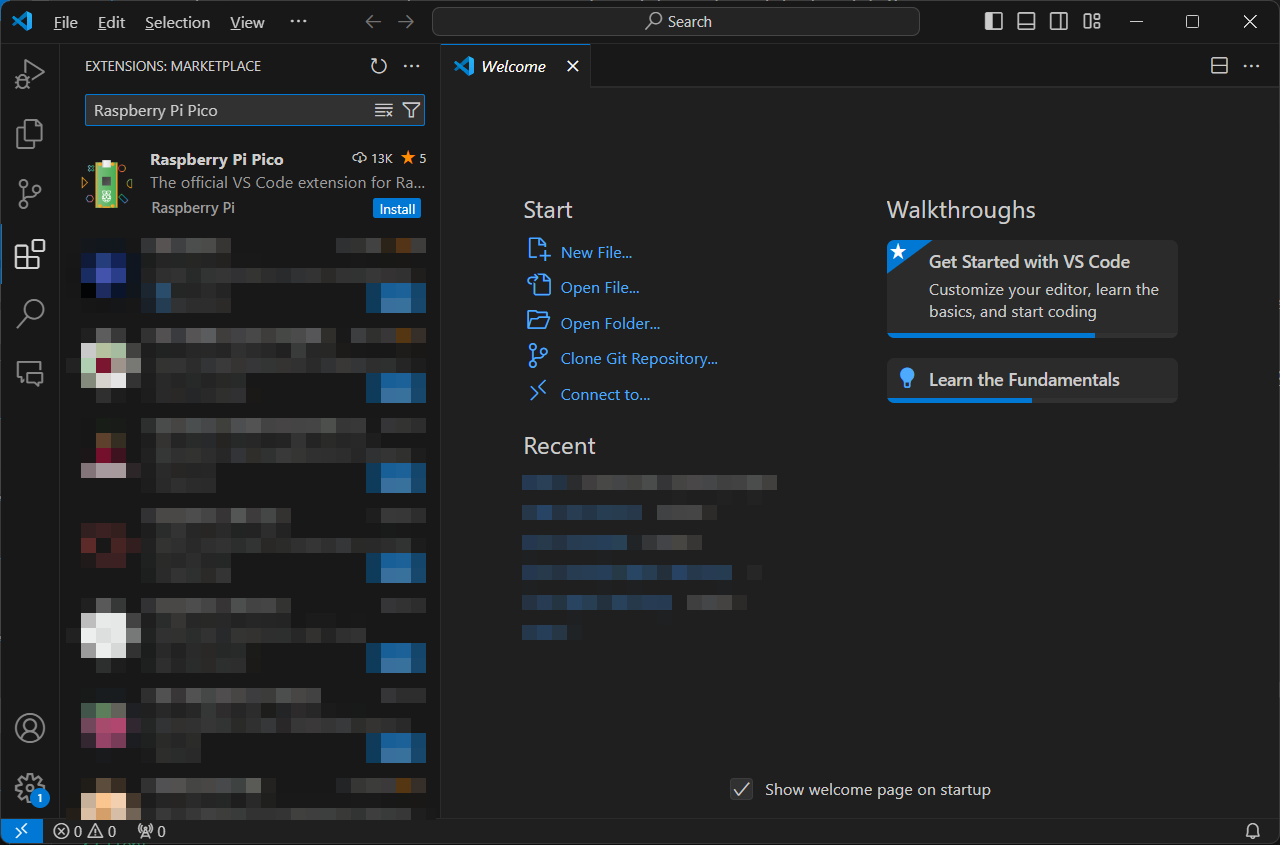
ステップ 1:拡張機能をインストールする
ステップ 2:新しいプロジェクトを作成する
ページが読み込まれると、必要なコンテンツが表示されます。
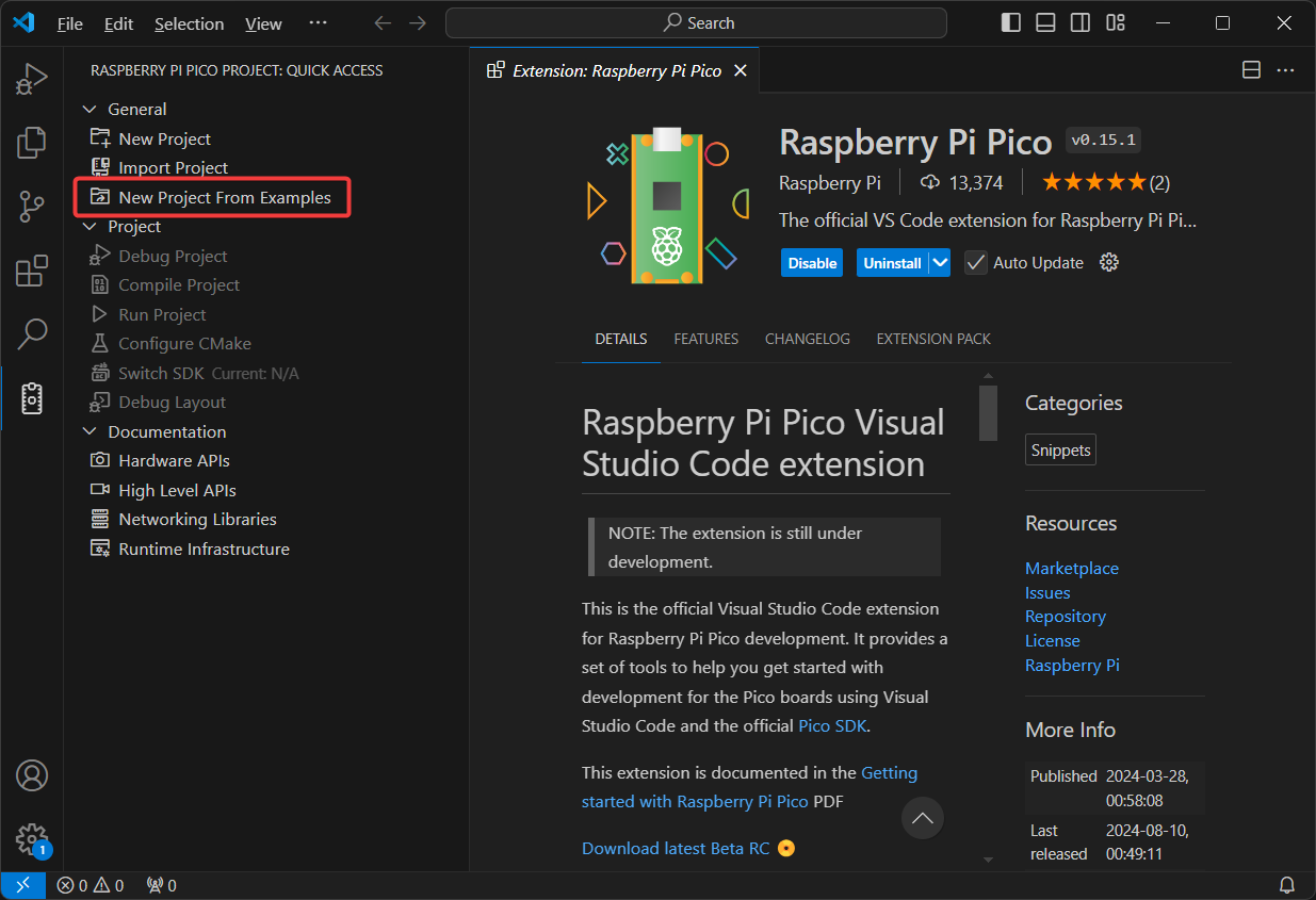
New Project From Examples を使用してプロジェクトを作成してみてください。
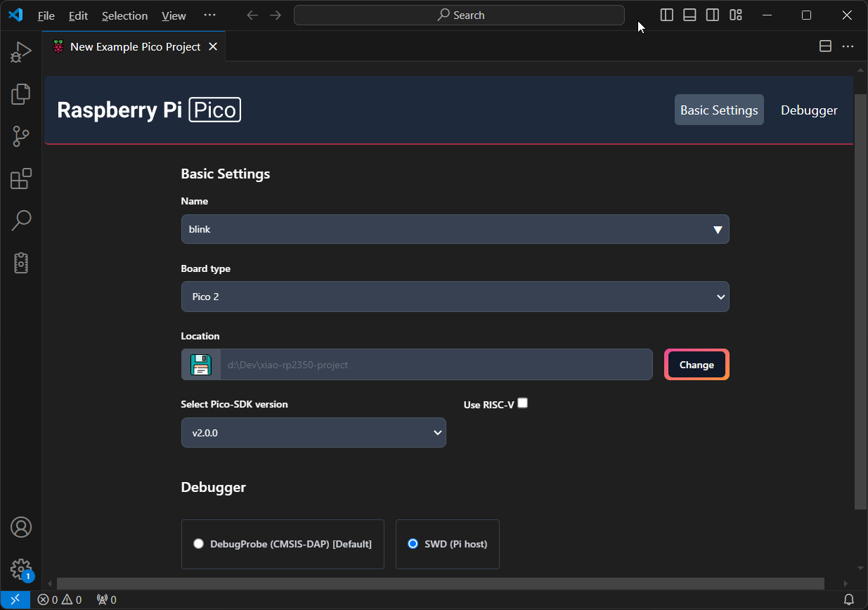
ステップ 3:プロジェクトを設定する
- Name: 通常、これはサンプル プロジェクト名になります。この場合、
blinkプロジェクトを選択します。 - Board Type:
Pico 2 - Location: XIAO RP2350 プロジェクトを保存する場所を選択します。
- SDK Version: バージョン
v2.0.0以降である必要があります。 - Debugger: SWD デバッグ インターフェースを使用する予定がある場合は、SWD Debugger オプションをチェックして後でデバッグを有効にします。
- プロジェクトの設定
- 詳細オプション
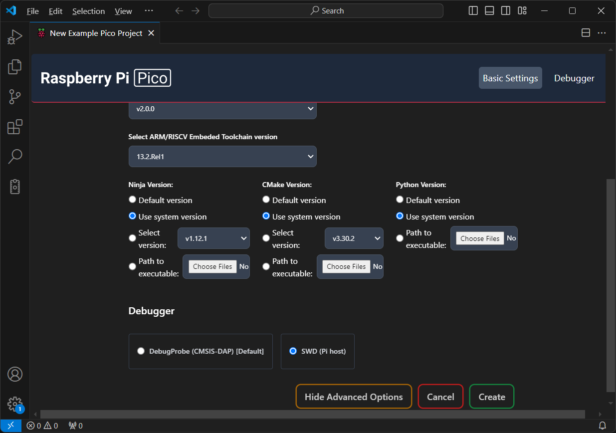
ツールチェーンのセットアップを細かく調整し、冗長なリソースのダウンロードを避けたい場合は、Advanced Options をチェックしてください。ここで、Ninja や CMake などのツールのパスを指定できます。以前に CMake や Python 環境をインストールしていない場合、または心配したくない場合は、この手順をスキップできます。
この例では、Windows マシンにすでにインストールされ、システム PATH に追加されているシステム バージョンを使用します。したがって、Use system version を選択します。
これが初回セットアップの場合、Create をクリックすると、拡張機能が SDK をダウンロードして管理します。Windows では、SDK は通常 %userprofile%.pico-sdk に配置されます。セットアップにかかる時間は、インターネット速度によって異なります。完了すると、プロジェクトを含む新しいウィンドウが開きます。
ステップ 4:プロジェクトをビルドする
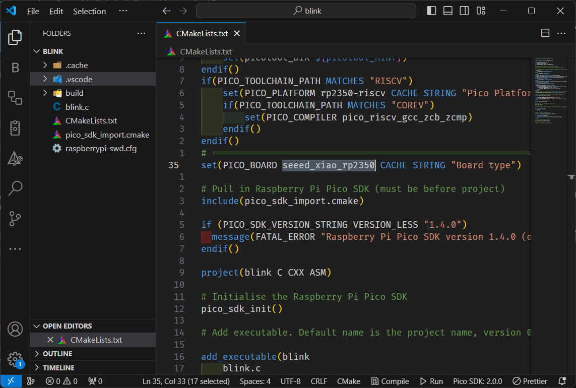
プロジェクトを初めてセットアップする際は、拡張機能にはデフォルトで XIAO RP2350 ボードが含まれていないため、CMake プロジェクトでボード タイプを手動で変更する必要があります。以下に示すように、ボードを seeed_xiao_rp2350 に設定してください:
ボード タイプを変更した後、build フォルダーをクリーンアップして、%userprofile%/.pico-sdk/sdk/2.0.0/src/boards/include/boards/seeed_xiao_rp2350.h から正しいボード設定を使用することを確認してください。次に、以下のコマンドを入力して、build フォルダーに CMake キャッシュを生成します:
cmake .. # in build folder
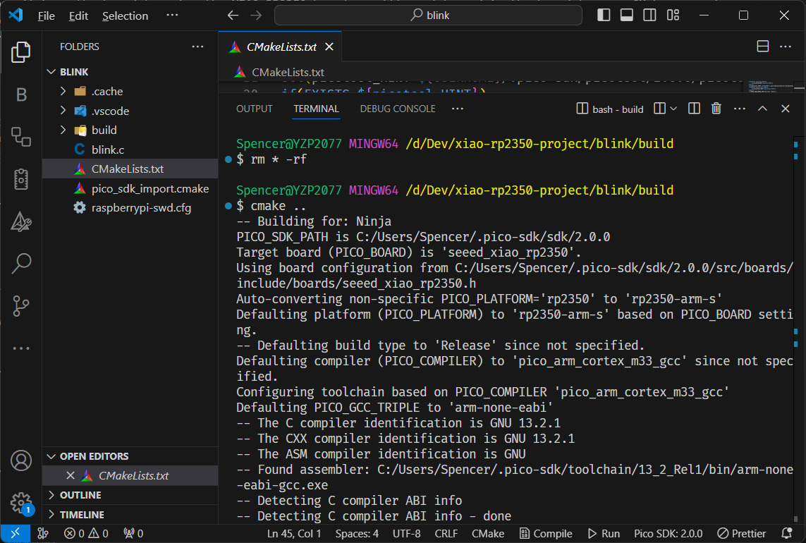
これにより、拡張機能のコンパイルタスクが正常に動作するようになります。
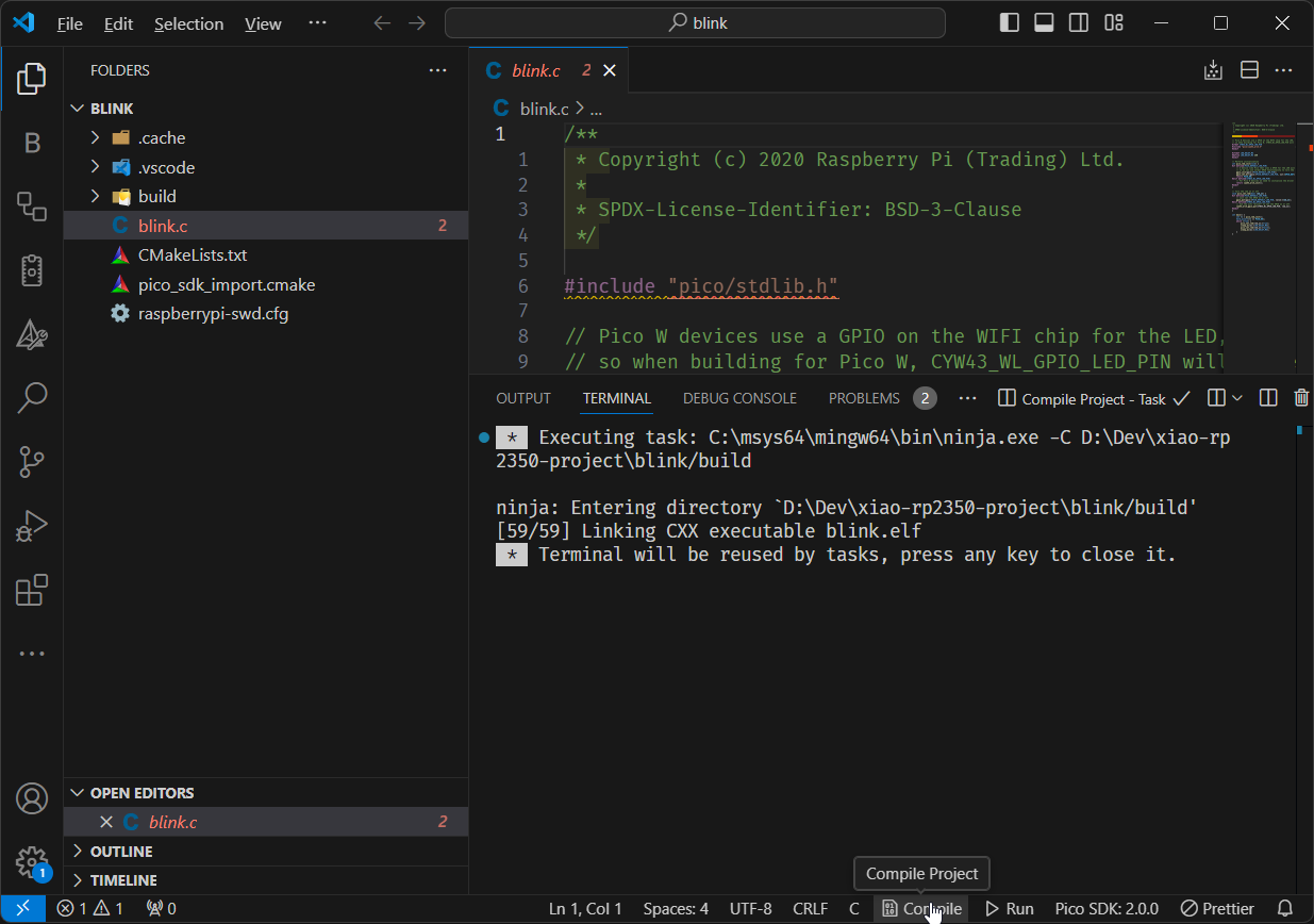
- Compile Project
- Run Project
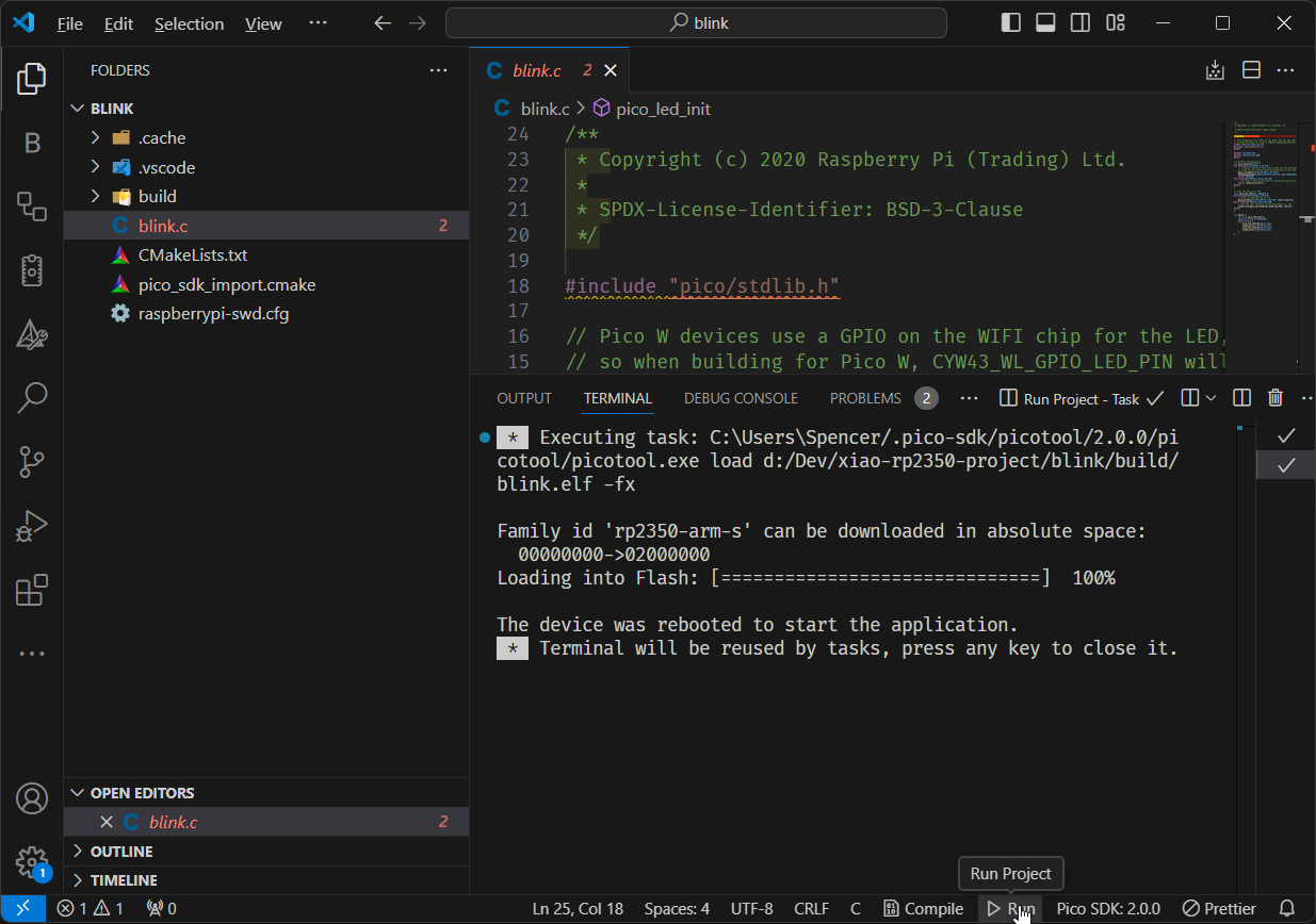
これでCompileボタンを押してプロジェクトをビルドできます。これによりbuildフォルダにblink.uf2ファイルが生成され、コンピューターが認識するRP2350ドライブにドラッグアンドドロップできます。
デバイスがBOOTモードの場合、Runボタンを押してコンパイルし、.uf2ファイルをRP2350に自動的にコピーできます。これにより、手動でファイルをドラッグアンドドロップする必要がなくなります。
開発環境をセットアップし、VSCode用Raspberry Pi Pico拡張機能を使用して新しいプロジェクトを正常に作成しました。プロジェクトの準備とツールの設定が完了したので、XIAO RP2350でコードを簡単にコンパイルして実行でき、開発プロセスを効率化できます。
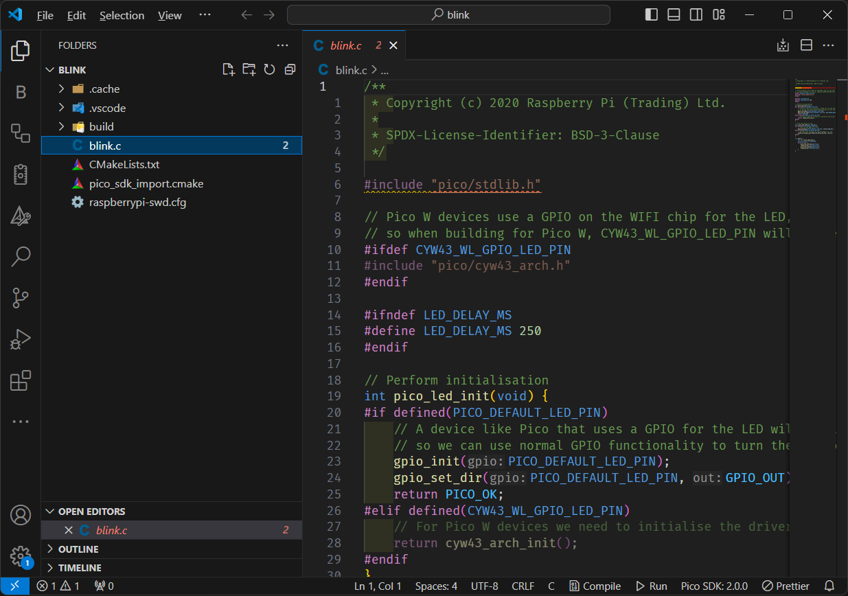
例1: LED点滅
基本的なSDKの使用方法を実演するため、以下の例では内蔵LEDを点滅させるプログラミングについて詳しく説明します:
#include "pico/stdlib.h"

const int sleep_time = 250;

int main() {
    const uint LED_PIN = PICO_DEFAULT_LED_PIN; // GPIO25
    gpio_init(LED_PIN);
    gpio_set_dir(LED_PIN, GPIO_OUT);
    while (true) {
        gpio_put(LED_PIN, 1);
        sleep_ms(sleep_time);
        gpio_put(LED_PIN, 0);
        sleep_ms(sleep_time);
    }
}
例2: RGB点滅
- ws2812.c
- ws2812.pio
- CMakeLists.txt
/**
 * Copyright (c) 2020 Raspberry Pi (Trading) Ltd.
 *
 * SPDX-License-Identifier: BSD-3-Clause
 */

#include <stdio.h>
#include <stdlib.h>

#include "pico/stdlib.h"
#include "hardware/pio.h"
#include "hardware/clocks.h"
#include "ws2812.pio.h"

#define IS_RGBW true
#define NUM_PIXELS 1

#ifdef PICO_DEFAULT_WS2812_PIN
#define WS2812_PIN PICO_DEFAULT_WS2812_PIN
#else
// default to pin 2 if the board doesn't have a default WS2812 pin defined
#define WS2812_PIN 22
#endif

static inline void put_pixel(uint32_t pixel_grb) {
    pio_sm_put_blocking(pio0, 0, pixel_grb << 8u);
}

static inline uint32_t urgb_u32(uint8_t r, uint8_t g, uint8_t b) {
    return
            ((uint32_t) (r) << 8) |
            ((uint32_t) (g) << 16) |
            (uint32_t) (b);
}

void pattern_snakes(uint len, uint t) {
    for (uint i = 0; i < len; ++i) {
        uint x = (i + (t >> 1)) % 64;
        if (x < 10)
            put_pixel(urgb_u32(0xff, 0, 0));
        else if (x >= 15 && x < 25)
            put_pixel(urgb_u32(0, 0xff, 0));
        else if (x >= 30 && x < 40)
            put_pixel(urgb_u32(0, 0, 0xff));
        else
            put_pixel(0);
    }
}

void pattern_random(uint len, uint t) {
    if (t % 8)
        return;
    for (int i = 0; i < len; ++i)
        put_pixel(rand());
}

void pattern_sparkle(uint len, uint t) {
    if (t % 8)
        return;
    for (int i = 0; i < len; ++i)
        put_pixel(rand() % 16 ? 0 : 0xffffffff);
}

void pattern_greys(uint len, uint t) {
    int max = 100; // let's not draw too much current!
    t %= max;
    for (int i = 0; i < len; ++i) {
        put_pixel(t * 0x10101);
        if (++t >= max) t = 0;
    }
}

typedef void (*pattern)(uint len, uint t);
const struct {
    pattern pat;
    const char *name;
} pattern_table[] = {
        {pattern_snakes,  "Snakes!"},
        {pattern_random,  "Random data"},
        {pattern_sparkle, "Sparkles"},
        {pattern_greys,   "Greys"},
};

int main() {
    //set_sys_clock_48();
    stdio_init_all();

    const int RGB_POWER = 23;
    gpio_init(RGB_POWER);
    gpio_set_dir(RGB_POWER, GPIO_OUT);
    gpio_put(RGB_POWER, 1);

    printf("WS2812 Smoke Test, using pin %d", WS2812_PIN);

    // todo get free sm
    PIO pio = pio0;
    int sm = 0;
    uint offset = pio_add_program(pio, &ws2812_program);

    ws2812_program_init(pio, sm, offset, WS2812_PIN, 800000, IS_RGBW);

    int t = 0;
    while (1) {
        int pat = rand() % count_of(pattern_table);
        int dir = (rand() >> 30) & 1 ? 1 : -1;
        puts(pattern_table[pat].name);
        puts(dir == 1 ? "(forward)" : "(backward)");
        for (int i = 0; i < 1000; ++i) {
            pattern_table[pat].pat(NUM_PIXELS, t);
            sleep_ms(10);
            t += dir;
        }
    }
}
;
; Copyright (c) 2020 Raspberry Pi (Trading) Ltd.
;
; SPDX-License-Identifier: BSD-3-Clause
;

.program ws2812
.side_set 1

.define public T1 2
.define public T2 5
.define public T3 3

.lang_opt python sideset_init = pico.PIO.OUT_HIGH
.lang_opt python out_init     = pico.PIO.OUT_HIGH
.lang_opt python out_shiftdir = 1

.wrap_target
bitloop:
    out x, 1       side 0 [T3 - 1] ; Side-set still takes place when instruction stalls
    jmp !x do_zero side 1 [T1 - 1] ; Branch on the bit we shifted out. Positive pulse
do_one:
    jmp  bitloop   side 1 [T2 - 1] ; Continue driving high, for a long pulse
do_zero:
    nop            side 0 [T2 - 1] ; Or drive low, for a short pulse
.wrap

% c-sdk {
#include "hardware/clocks.h"

static inline void ws2812_program_init(PIO pio, uint sm, uint offset, uint pin, float freq, bool rgbw) {

    pio_gpio_init(pio, pin);
    pio_sm_set_consecutive_pindirs(pio, sm, pin, 1, true);

    pio_sm_config c = ws2812_program_get_default_config(offset);
    sm_config_set_sideset_pins(&c, pin);
    sm_config_set_out_shift(&c, false, true, rgbw ? 32 : 24);
    sm_config_set_fifo_join(&c, PIO_FIFO_JOIN_TX);

    int cycles_per_bit = ws2812_T1 + ws2812_T2 + ws2812_T3;
    float div = clock_get_hz(clk_sys) / (freq * cycles_per_bit);
    sm_config_set_clkdiv(&c, div);

    pio_sm_init(pio, sm, offset, &c);
    pio_sm_set_enabled(pio, sm, true);
}
%}

.program ws2812_parallel

.define public T1 2
.define public T2 5
.define public T3 3

.wrap_target
    out x, 32
    mov pins, !null [T1-1]
    mov pins, x     [T2-1]
    mov pins, null  [T3-2]
.wrap

% c-sdk {
#include "hardware/clocks.h"

static inline void ws2812_parallel_program_init(PIO pio, uint sm, uint offset, uint pin_base, uint pin_count, float freq) {
    for(uint i=pin_base; i<pin_base+pin_count; i++) {
        pio_gpio_init(pio, i);
    }
    pio_sm_set_consecutive_pindirs(pio, sm, pin_base, pin_count, true);

    pio_sm_config c = ws2812_parallel_program_get_default_config(offset);
    sm_config_set_out_shift(&c, true, true, 32);
    sm_config_set_out_pins(&c, pin_base, pin_count);
    sm_config_set_set_pins(&c, pin_base, pin_count);
    sm_config_set_fifo_join(&c, PIO_FIFO_JOIN_TX);

    int cycles_per_bit = ws2812_parallel_T1 + ws2812_parallel_T2 + ws2812_parallel_T3;
    float div = clock_get_hz(clk_sys) / (freq * cycles_per_bit);
    sm_config_set_clkdiv(&c, div);

    pio_sm_init(pio, sm, offset, &c);
    pio_sm_set_enabled(pio, sm, true);
}
%}
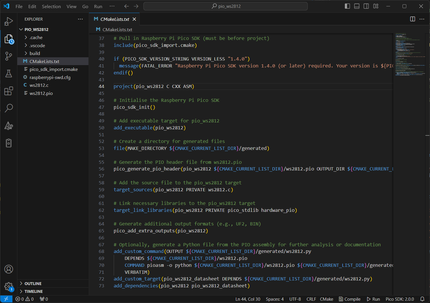
以下のスニペットをコピーして、CMakeLists.txt ファイルに追加してください。
project(pio_ws2812 C CXX ASM)

# Initialise the Raspberry Pi Pico SDK
pico_sdk_init()

# Add executable target for pio_ws2812
add_executable(pio_ws2812)

# Create a directory for generated files
file(MAKE_DIRECTORY ${CMAKE_CURRENT_LIST_DIR}/generated)

# Generate the PIO header file from ws2812.pio
pico_generate_pio_header(pio_ws2812 ${CMAKE_CURRENT_LIST_DIR}/ws2812.pio OUTPUT_DIR ${CMAKE_CURRENT_LIST_DIR}/generated)

# Add the source file to the pio_ws2812 target
target_sources(pio_ws2812 PRIVATE ws2812.c)

# Link necessary libraries to the pio_ws2812 target
target_link_libraries(pio_ws2812 PRIVATE pico_stdlib hardware_pio)

# Generate additional output formats (e.g., UF2, BIN)
pico_add_extra_outputs(pio_ws2812)

# Optionally, generate a Python file from the PIO assembly for further analysis or documentation
add_custom_command(OUTPUT ${CMAKE_CURRENT_LIST_DIR}/generated/ws2812.py
    DEPENDS ${CMAKE_CURRENT_LIST_DIR}/ws2812.pio
    COMMAND pioasm -o python ${CMAKE_CURRENT_LIST_DIR}/ws2812.pio ${CMAKE_CURRENT_LIST_DIR}/generated/ws2812.py
    VERBATIM)
add_custom_target(pio_ws2812_datasheet DEPENDS ${CMAKE_CURRENT_LIST_DIR}/generated/ws2812.py)
add_dependencies(pio_ws2812 pio_ws2812_datasheet)
例3: UART出力
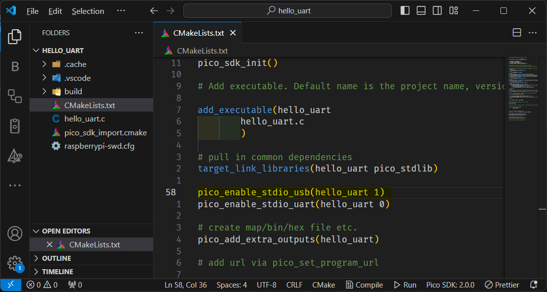
printf 出力をUSB経由でコンピュータに有効にしたい場合は、プロジェクトの CMakeLists.txt ファイルに以下の行を追加して設定する必要があります:
pico_enable_stdio_usb(your_project_name 1)
さらに、メイン関数に stdio_init_all(); を追加して、コード内で標準I/Oを初期化することを確認してください。
#include "hardware/uart.h"
#include "pico/stdlib.h"
#include <pico/stdio.h>
#include <pico/time.h>
#include <stdio.h>

#define UART_ID uart0
#define BAUD_RATE 115200

// We are using pins 0 and 1, but see the GPIO function select table in the
// datasheet for information on which other pins can be used.
#define UART_TX_PIN 0
#define UART_RX_PIN 1

int main() {
   stdio_init_all();
  // Set up our UART with the required speed.
  uart_init(UART_ID, BAUD_RATE);

  // Set the TX and RX pins by using the function select on the GPIO
  // Set datasheet for more information on function select
  gpio_set_function(UART_TX_PIN, UART_FUNCSEL_NUM(UART_ID, UART_TX_PIN));
  gpio_set_function(UART_RX_PIN, UART_FUNCSEL_NUM(UART_ID, UART_RX_PIN));

  // Use some the various UART functions to send out data
  // In a default system, printf will also output via the default UART

  // Send out a character without any conversions
  uart_putc_raw(UART_ID, 'A');

  // Send out a character but do CR/LF conversions
  uart_putc(UART_ID, 'B');

  // Send out a string, with CR/LF conversions
  uart_puts(UART_ID, " Hello, UART!\n");

  // Print test
  int i = 0;
  for (;;) {
    sleep_ms(500);
    printf("Hello %d", i++);
  }
}
例 4: バッテリー電圧の読み取り
#include <stdio.h>
#include "pico/stdlib.h"
#include "hardware/gpio.h"
#include "hardware/adc.h"

void init_gpio() {
    const int gpio = 19;

    gpio_init(gpio);
    gpio_set_dir(gpio, GPIO_OUT);
    gpio_put(gpio, 1);
}

int main() {
    stdio_init_all();
    printf("ADC battery Example - GPIO29 A3\n");

    init_gpio();
    adc_init();

    // Make sure GPIO is high-impedance, no pullups etc
    adc_gpio_init(29);
    // Select ADC input 0 (GPIO26)
    adc_select_input(3);

    while (1) {
        // 12-bit conversion, assume max value == ADC_VREF == 3.3 V
        const float conversion_factor = 3.3f / (1 << 12);
        uint16_t result = adc_read();
        printf("Raw value: 0x%03x, voltage: %f V\n", result, result * conversion_factor * 2);
        sleep_ms(500);
    }
}
FAQ
TinyUSB サブモジュールが初期化されていません;USB サポートが利用できません
問題: プロジェクトをビルドする際に、この警告が表示される場合があります:
TinyUSB submodule has not been initialized; USB support will be unavailable
解決方法:
-
ターミナルを開く Linux/macOSの場合、またはWindowsの場合はコマンドプロンプト/PowerShell/Git Bashを開く。
-
Pico SDKディレクトリに移動:
cd /path/to/your/pico-sdk -
サブモジュールを初期化する:
git submodule update --init
これにより、プロジェクトでUSBサポートが有効になります。
Resources
- 🔗 [Link] Raspberry Pi Pico SDK | GitHub
- 📄 [PDF] Raspberry Pi Pico-series C/C++SDK SDK APIを文書化した書籍
- 📄 [PDF] Getting started with Raspberry Pi Pico-series - 公式Raspberry Piドキュメント。
- 📽️ [Video] Intro to Raspberry Pi Pico and RP2040 - ビデオチュートリアル。
技術サポート・製品ディスカッション
私たちの製品をお選びいただき、ありがとうございます!私たちは、お客様の製品体験が可能な限りスムーズになるよう、さまざまなサポートを提供しています。異なる好みやニーズに対応するため、複数のコミュニケーションチャンネルを提供しています。