Seeed Studio XIAO ESP32C3 と MicroPython
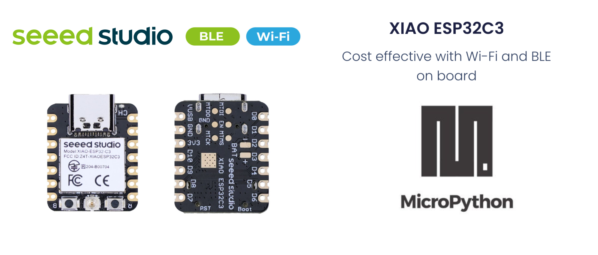
MicroPython は、部分的なネイティブコードコンパイル機能を持つPythonインタープリターです。組み込みプロセッサーや制約のあるシステム向けに実装されたPython 3.5機能のサブセットを提供します。CPythonとは異なり、その違いについてはこちらで詳しく読むことができます。
MicroPython のインストール
Esptool のインストール
まだ esptool.py をインストールしていない場合は、PC上でpipを使用してインストールできます:
pip install esptool
XIAO ESP32C3 MicroPython ファームウェアをダウンロードする
micropython.orgからファームウェアバイナリファイルをダウンロードする必要があります。 正しいbinファイルをダウンロードした後、そのフォルダに移動し、そこでcmdターミナルを開きます。 最終稿の時点で、binファイルの最新バージョンは以下の通りです:
ESP32_GENERIC_C3-20230602-v1.23.0.bin
XIAO ESP32C3 をPCに接続する
XIAO ESP32C3 ボードのBOOTボタンを押し続けながら、Type C USBケーブルでPCに接続して「ブートローダー」モードに入る必要があります。
ポートを確認する
PC上のすべてのシリアルデバイスを見つけます。
- Linux
Linuxでは、dmesg コマンドを使用して接続されたデバイスを表示できます:
dmesg | grep tty
または、lsを使用してシリアルデバイスを一覧表示することもできます:
ls /dev/ttyS* /dev/ttyUSB*
- Windows
Windowsでは、デバイスマネージャーを通じてシリアルポートを確認できます。利用可能なシリアルポートを確認するには、「ポート (COM と LPT)」セクションを探してください。また、コマンドプロンプトでmodeコマンドを使用してシリアルポートを一覧表示することもできます:
mode
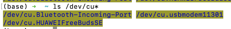
- macOS
macOSでは、lsコマンドを使用して利用可能なシリアルポートを一覧表示できます:
ls /dev/cu*
これにより、すべてのシリアルポートデバイスが表示されます。
ポートがビジー状態の場合、以下のコマンドを使用してポートを使用しているプロセスを見つけて終了できます(macOS上で): ポートを使用しているプロセスを特定する:
lsof | grep port
このコマンドは開いているファイルを一覧表示し、指定されたポートを使用しているプロセスを検索します。 出力からプロセスID(PID)を見つけて、そのプロセスを終了させます:
kill -9 <PID>
PID を実際に見つかったプロセス ID に置き換えてください。
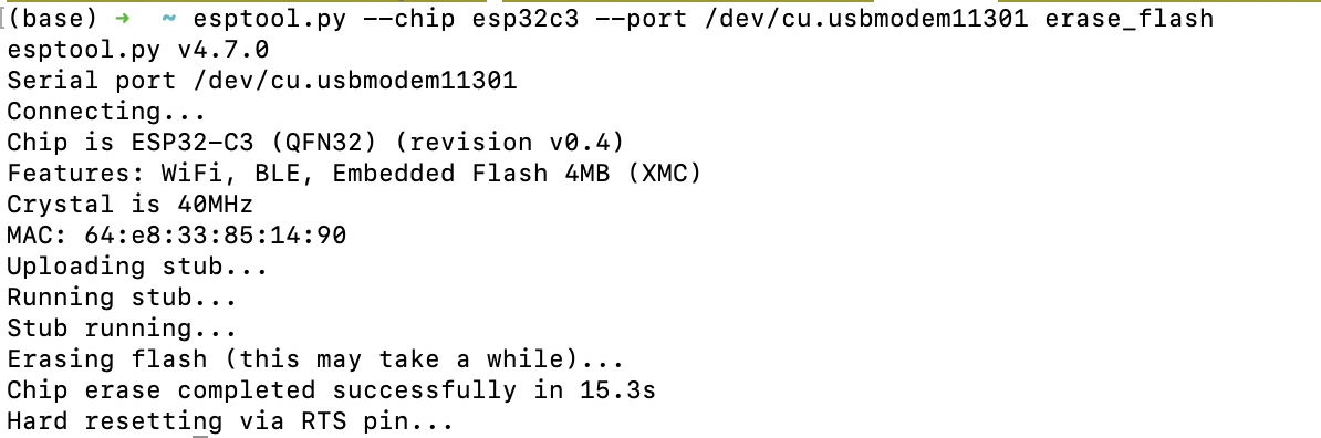
フラッシュの消去
esptool.py --chip esp32c3 --port /dev/cu.usbmodem11301 erase_flash
'/dev/cu.usbmodem11301' をあなたのシステムの正しいポート名に置き換えてください(例:Windowsでは COM3、Linuxでは /dev/ttyUSB0)。
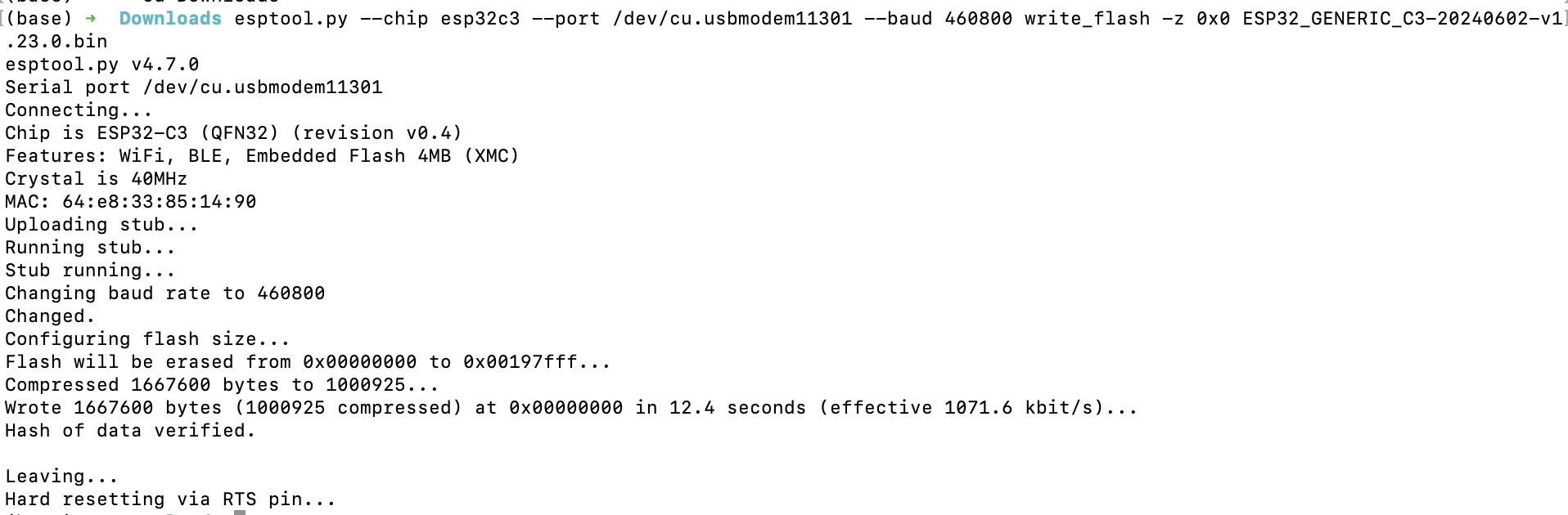
フラッシュ書き込み
XIAO ESP32C3 にファームウェアをフラッシュします:
esptool.py --chip esp32c3 --port /dev/cu.usbmodem11301 --baud 460800 write_flash -z 0x0 ESP32_GENERIC_C3-20240602-v1.23.0.bin
再度、'/dev/cu.usbmodem11301' を正しいポート名に、'ESP32_GENERIC_C3-20240602-v1.23.0.bin' をブランクファームウェアファイルのパスに置き換えてください。
その後、お好みのツールを使用してESP32にスクリプトをコンパイルし始めることができます!
MicroPythonの推奨エディタ
人気のあるツールの一部を以下に示します。
1. Thonny
Thonnyをインストールして開き、以下の手順に従ってThonnyを設定します:
pip install thonny
#open thonny after installation
thonny
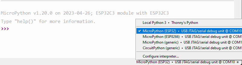
Run-->Configure Interpreterに移動し、Thonnyオプションのインタープリタータブが以下のように表示されることを確認し、"CircuitPython (generic)"とポートを選択してください:
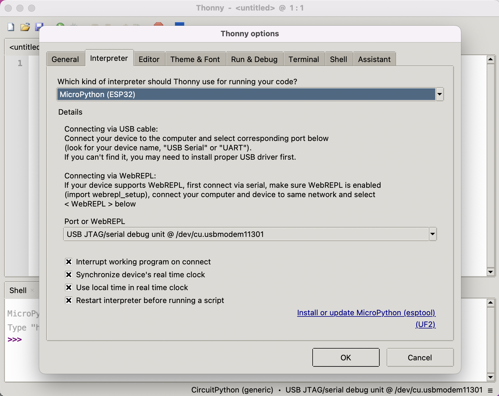
ダイアログで「OK」をクリックすると、下図に示すようにthonnyウィンドウの下部にMicropythonシェルが表示されます。 フラッシュとSRAMサイズを取得するために、シェルにスクリプトを1行ずつ入力してください:
import gc
gc.mem_free()

import esp
esp.flash_size()
XIAO ESP32C3でThonnyを使用してMicroPythonのセットアップが正常に完了しました。おめでとうございます!
2. MicroPython用Arduino Lab
Arduino lab for MicroPythonをダウンロードし、デバイスをPCに接続します。
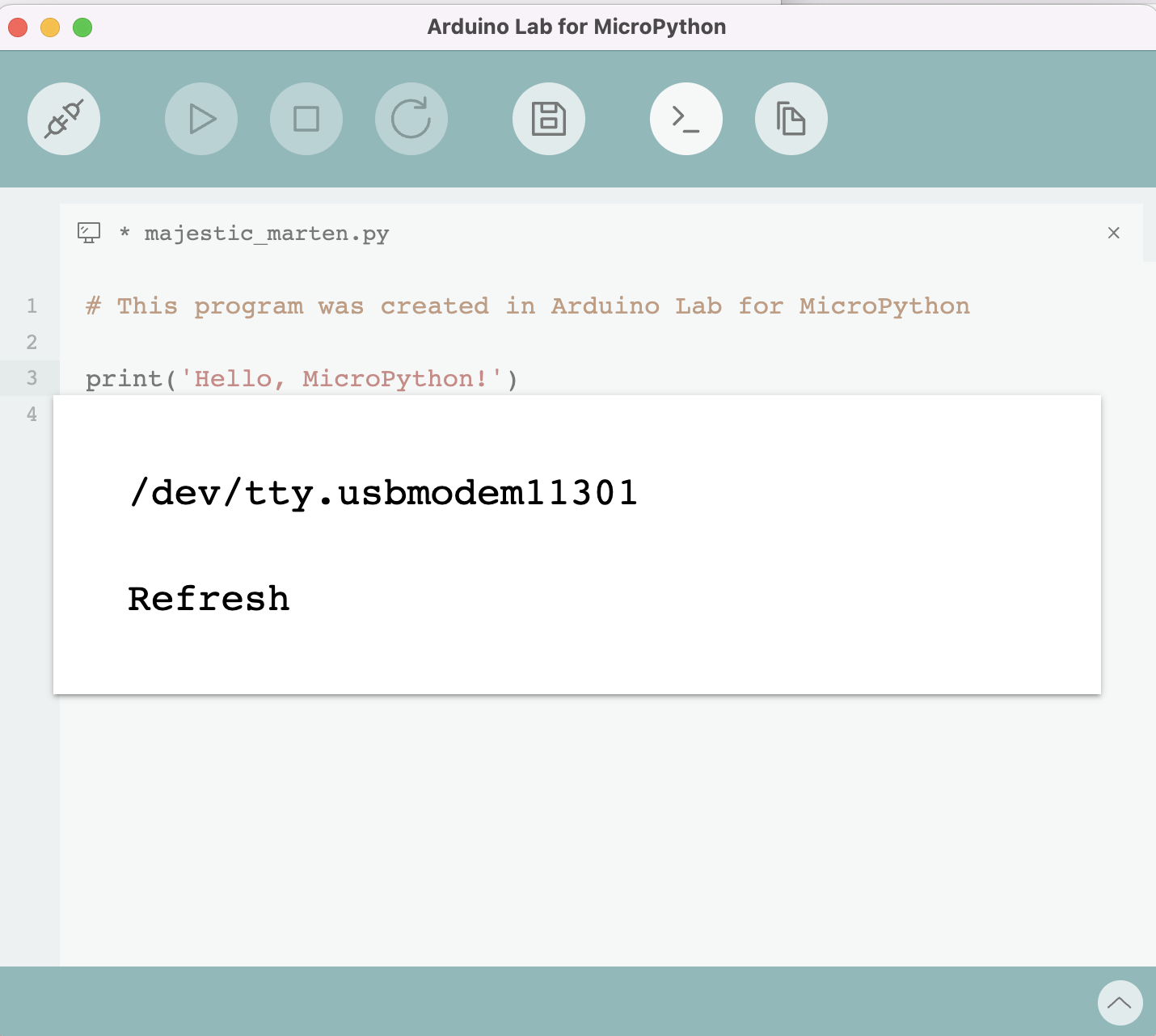
次のようにコードを書きます:
from machine import Pin
import time

# Define the LED pin
led = Pin(7, Pin.OUT)  # Use the correct GPIO number instead of D10

# Blink the LED in a loop
while True:
    led.value(1)   # Turn the LED on
    time.sleep(1)  # Wait for a second
    led.value(0)   # Turn the LED off
    time.sleep(1)  # Wait for a second
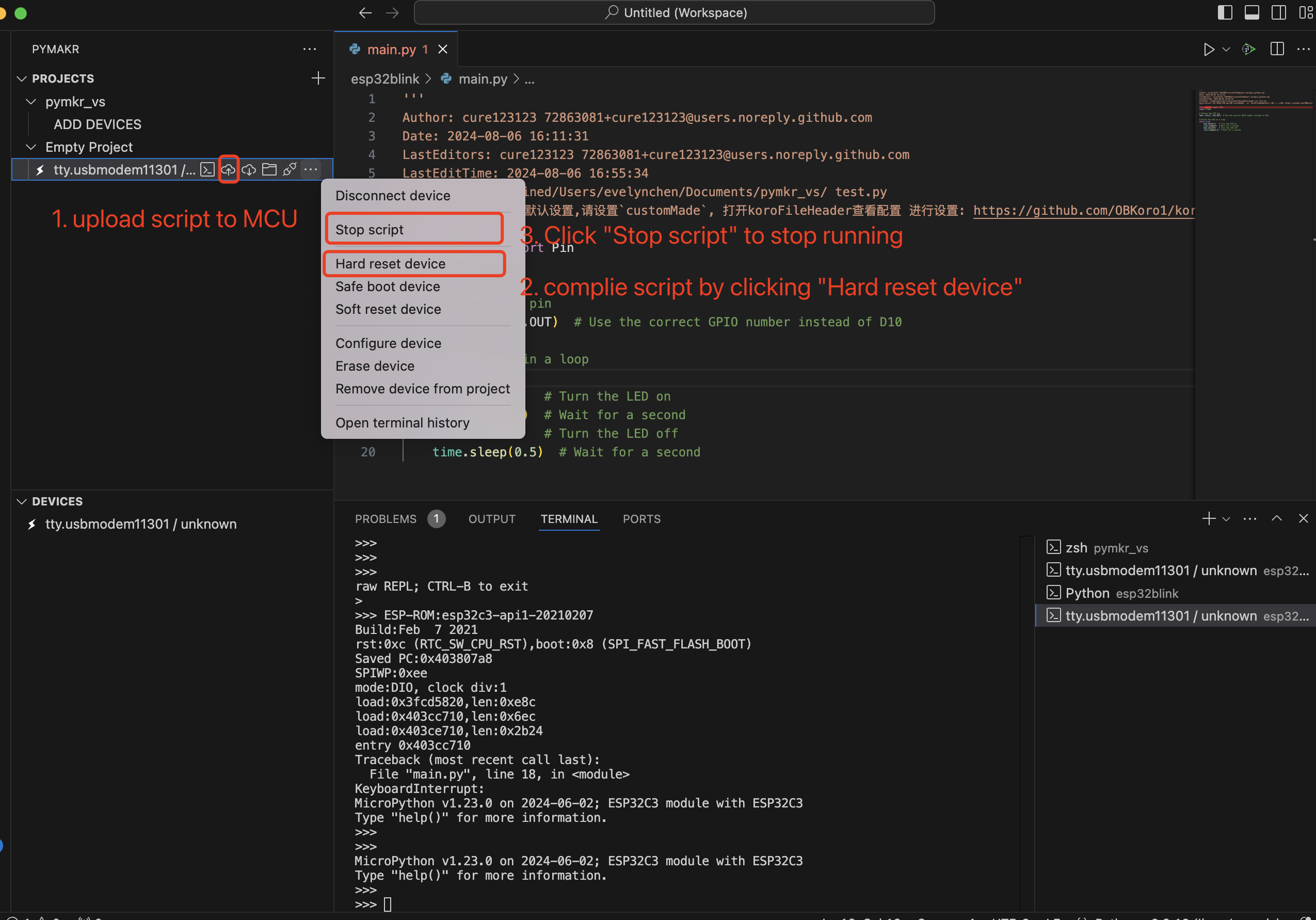
3. Visual Studio Code上のPymakr
-
Pymakrのインストール インストール手順に従ってPymakrをインストールしてください。
-
XIAO ESP32C3をコンピュータに接続します。
-
新しいプロジェクトを作成 VS Codeを開き、マイクロコントローラー用の新しいプロジェクトを作成します。
-
新しいPythonファイルを追加 プロジェクト内に新しいPythonファイルを作成します。
-
スクリプトをMCUにアップロードしてスクリプトをコンパイル
4. uPtCraft IDE
ピンアウト/ポート情報
- 詳細情報についてはハードウェア概要を参照してください
- Seeed Studio XIAO ESP32C3 回路図
XIAO ESP32C3でのMicroPythonの開始
こちらはmicropythonによるESP32操作のクイックリファレンスです。 micropythonライブラリについての詳細な知識については、こちらを参照してください。
一般的なボード制御
MicroPython REPL(Read-Eval-Print-Loop)はUART0(GPIO1=TX、GPIO3=RX)上でボーレート115200で動作します。タブ補完は、オブジェクトが持つメソッドを調べるのに便利です。ペーストモード(ctrl-E)は、大きなPythonコードの塊をREPLに貼り付けるのに便利です。 MicroPython(Pythonと同様)で*dir()関数を使用して、オブジェクトの属性とメソッドをリストできます。 例えば、シェルにdir(machine)*と入力します:
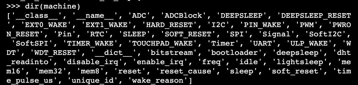
machineモジュール:
import machine
machine.freq()          # get the current frequency of the CPU, for esp32c3 is 160000000
machine.freq(160000000) # set the CPU frequency to 160 MHz
esp モジュール:
import esp

esp.osdebug(None)       # turn off vendor O/S debugging messages
esp.osdebug(0)          # redirect vendor O/S debugging messages to UART(0)

# low level methods to interact with flash storage
esp.flash_size()
esp.flash_user_start()
esp.flash_erase(sector_no)
esp.flash_write(byte_offset, buffer)
esp.flash_read(byte_offset, buffer)
esp32 モジュール: ESP32C3、ESP32S2、および ESP32S3 には内蔵温度センサーが利用可能で、摂氏温度を返します:
import esp32
esp32.mcu_temperature() # read the internal temperature of the MCU, in Celsius
Network-WLAN
Network モジュール: 詳細情報についてはこちらを参照してください。
import network

wlan = network.WLAN(network.STA_IF) # create station interface
wlan.active(True)       # activate the interface
wlan.scan()             # scan for access points
wlan.isconnected()      # check if the station is connected to an AP
wlan.connect('ssid', 'key') # connect to an AP
wlan.config('mac')      # get the interface's MAC address
wlan.ifconfig()  # get the interface's IPv4 addresses

ap = network.WLAN(network.AP_IF) # create access-point interface
ap.config(ssid='ESP-AP') # set the SSID of the access point
ap.config(max_clients=10) # set how many clients can connect to the network
ap.active(True)         # activate the interface
ローカルWiFiネットワークに接続するための便利な関数は以下の通りです:
def do_connect():
    import network
    wlan = network.WLAN(network.STA_IF)
    wlan.active(True)
    if not wlan.isconnected():
        print('connecting to network...')
        wlan.connect('ssid', 'key') #replace the ssid and key
        while not wlan.isconnected():
            pass
    print('network config:', wlan.ifconfig())
遅延とタイミング
The time module:
import time

time.sleep(1)           # sleep for 1 second
time.sleep_ms(500)      # sleep for 500 milliseconds
time.sleep_us(10)       # sleep for 10 microseconds
start = time.ticks_ms() # get millisecond counter
delta = time.ticks_diff(time.ticks_ms(), start) # compute time difference
タイマー
ESP32ポートには4つのハードウェアタイマーがあります。0から3(含む)のタイマーIDでクラスを使用してください:
from machine import Timer

tim0 = Timer(0)
tim0.init(period=5000, mode=Timer.ONE_SHOT, callback=lambda t:print(0))

tim1 = Timer(1)
tim1.init(period=2000, mode=Timer.PERIODIC, callback=lambda t:print(1))
この期間はミリ秒単位です。 仮想タイマーは現在このポートではサポートされていません。
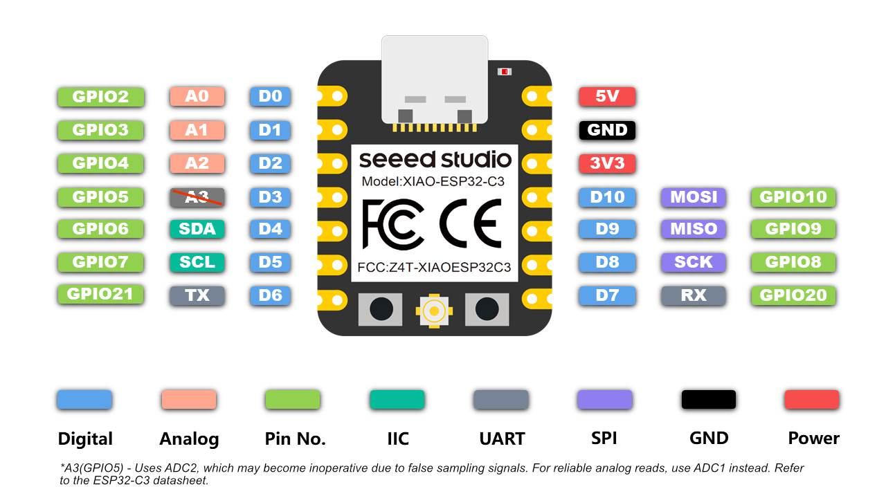
ピンとGPIO
machine.Pinクラス:
from machine import Pin

p2 = Pin(2, Pin.OUT)    # create output pin on GPIO2
p2.on()                 # set pin to "on" (high) level
p2.off()                # set pin to "off" (low) level
p2.value(1)             # set pin to on/high

p3 = Pin(3, Pin.IN)     # create input pin on GPIO3
print(p3.value())       # get value, 0 or 1

p4 = Pin(4, Pin.IN, Pin.PULL_UP) # enable internal pull-up resistor
p5 = Pin(5, Pin.OUT, value=1) # set pin high on creation
p6 = Pin(6, Pin.OUT, drive=Pin.DRIVE_3) # set maximum drive strength
利用可能なピンは以下の範囲(両端を含む)からです:2,3,4,5,6,7,8,9,10,20,21。これらはESP32C3チップの実際のGPIOピン番号に対応しています。
UART(シリアルバス)
machine.UARTクラス:
from machine import UART

uart1 = UART(1, baudrate=9600, tx=21, rx=20)
uart1.write('hello')  # write 5 bytes
uart1.read(5)         # read up to 5 bytes
ESP32C3には1つのハードウェアUARTがあります。以下にピンを示します:
| UART | Pin |
|---|---|
| TX | 21 |
| RX | 20 |
PWM(パルス幅変調)
PWMは出力可能なすべてのピンで有効にできます。基本周波数は1Hzから40MHzまでの範囲ですが、トレードオフがあります;基本周波数が増加するとデューティ分解能が減少します。 machine.PWMクラス:
from machine import Pin, PWM

pwm2 = PWM(Pin(2), freq=5000, duty_u16=32768) # create PWM object from a pin
freq = pwm2.freq()         # get current frequency
pwm2.freq(1000)            # set PWM frequency from 1Hz to 40MHz

duty = pwm2.duty()         # get current duty cycle, range 0-1023 (default 512, 50%)
pwm2.duty(256)             # set duty cycle from 0 to 1023 as a ratio duty/1023, (now 25%)

duty_u16 = pwm2.duty_u16() # get current duty cycle, range 0-65535
pwm2.duty_u16(2**16*3//4)  # set duty cycle from 0 to 65535 as a ratio duty_u16/65535, (now 75%)

duty_ns = pwm2.duty_ns()   # get current pulse width in ns
pwm2.duty_ns(250_000)      # set pulse width in nanoseconds from 0 to 1_000_000_000/freq, (now 25%)

pwm2.deinit()              # turn off PWM on the pin

pwm3 = PWM(Pin(3), freq=20000, duty=512)  # create and configure in one go
print(pwm3)                               # view PWM settings
ESP チップには異なるハードウェア周辺機器があります:
| ハードウェア仕様 | ESP32C3 | ESP32 |
|---|---|---|
| グループ数(スピードモード) | 1 | 2 |
| グループあたりのタイマー数 | 4 | 4 |
| グループあたりのチャンネル数 | 6 | 8 |
| 異なるPWM周波数(グループ × タイマー) | 4 | 8 |
| 総PWMチャンネル数(ピン、デューティ)(グループ × チャンネル) | 6 | 16 |
ADC(アナログ・デジタル変換)
XIAO ESP32C3 では、ADC機能はピン2、3、4で利用できます。
A3(GP105) - ADC2を使用しており、偽のサンプリング信号により動作不能になる可能性があります。アナログ読み取りには、代わりにADC1(A0/A1/A2)を使用してください。XIAO ESP32C3 データシートを参照してください。
machine.ADC クラス:
from machine import ADC

adc = ADC(pin)        # create an ADC object acting on a pin
val = adc.read_u16()  # read a raw analog value in the range 0-65535
val = adc.read_uv()   # read an analog value in microvolts
SPI
ソフトウェア SPI バス
ソフトウェア SPI(ビットバンギングを使用)はすべてのピンで動作し、machine.SoftSPI クラス経由でアクセスされます:
from machine import Pin, SoftSPI

# construct a SoftSPI bus on the given pins
# polarity is the idle state of SCK
# phase=0 means sample on the first edge of SCK, phase=1 means the second
spi = SoftSPI(baudrate=100000, polarity=1, phase=0, sck=Pin(2), mosi=Pin(4), miso=Pin(6))

spi.init(baudrate=200000) # set the baudrate

spi.read(10)            # read 10 bytes on MISO
spi.read(10, 0xff)      # read 10 bytes while outputting 0xff on MOSI

buf = bytearray(50)     # create a buffer
spi.readinto(buf)       # read into the given buffer (reads 50 bytes in this case)
spi.readinto(buf, 0xff) # read into the given buffer and output 0xff on MOSI

spi.write(b'12345')     # write 5 bytes on MOSI

buf = bytearray(4)      # create a buffer
spi.write_readinto(b'1234', buf) # write to MOSI and read from MISO into the buffer
spi.write_readinto(buf, buf) # write buf to MOSI and read MISO back into buf
ハードウェア SPI バス
ハードウェア SPI は machine.SPI クラス経由でアクセスされ、上記のソフトウェア SPI と同じメソッドを持ちます:
from machine import Pin, SPI

hspi = SPI(1, 10000000)
hspi = SPI(1, 10000000, sck=Pin(8), mosi=Pin(10), miso=Pin(9))
| SPI | ピン |
|---|---|
| SCK | D8 |
| MOSI | D10 |
| MISO | D9 |
I2C
ソフトウェアI2Cバス
ソフトウェアI2C(ビットバンギングを使用)は、すべての出力可能なピンで動作し、machine.SoftI2C クラスを介してアクセスされます:
from machine import Pin, SoftI2C

i2c = SoftI2C(scl=Pin(7), sda=Pin(6), freq=100000)

i2c.scan()              # scan for devices

i2c.readfrom(0x3a, 4)   # read 4 bytes from device with address 0x3a
i2c.writeto(0x3a, '12') # write '12' to device with address 0x3a

buf = bytearray(10)     # create a buffer with 10 bytes
i2c.writeto(0x3a, buf)  # write the given buffer to the peripheral
ハードウェアI2Cバス
ドライバは machine.I2C クラス経由でアクセスされ、上記のソフトウェアI2Cと同じメソッドを持ちます:
from machine import Pin, I2C
i2c = I2C(0, scl=Pin(7), sda=Pin(6), freq=400000)
| I2C | GPIO | Pin |
|---|---|---|
| SCL | GPIO7 | D5 |
| SDA | GPIO6 | D4 |
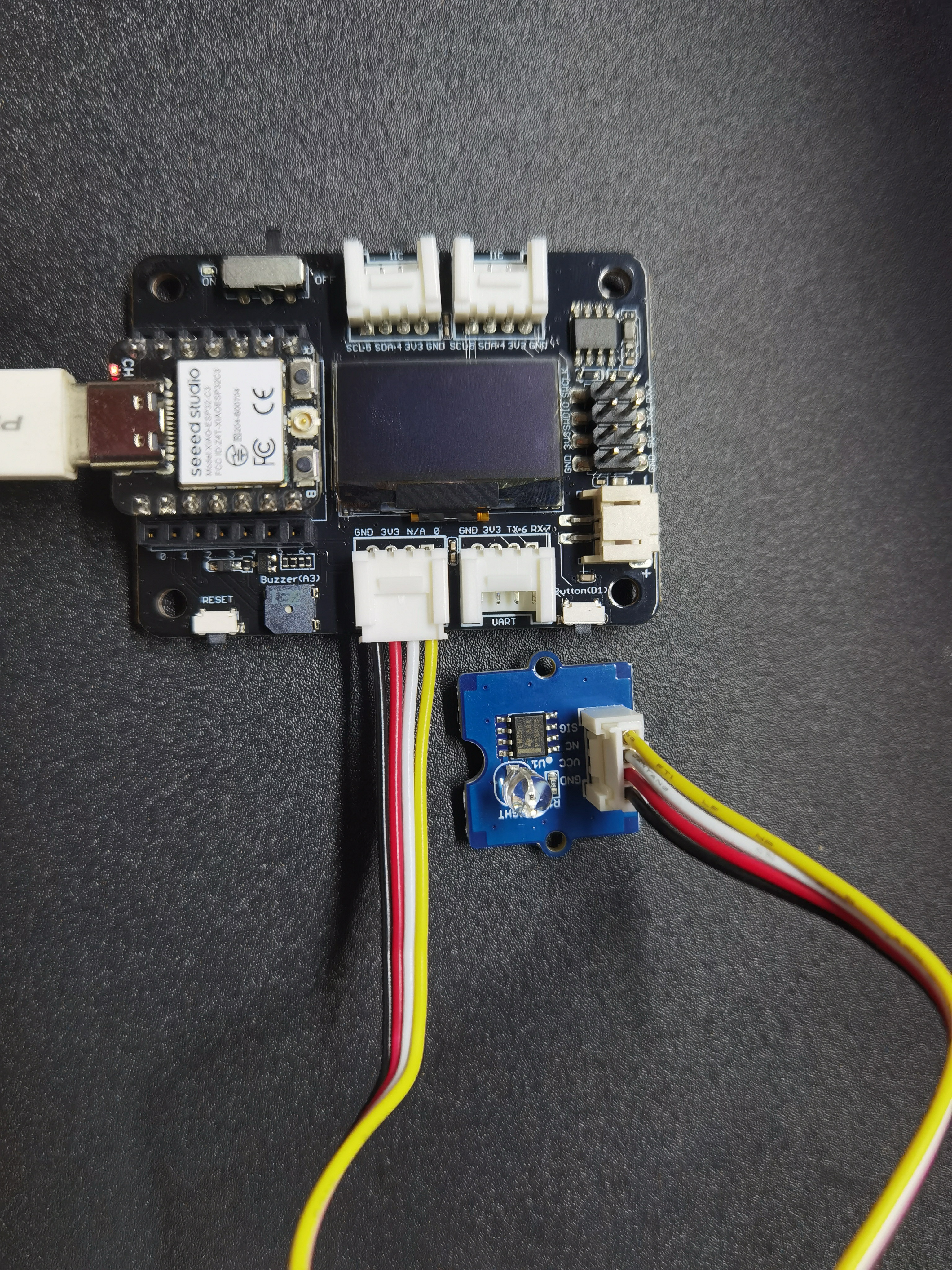
XIAO用拡張ボードベース
前提条件:
| ヘッダーはんだ付け済み XIAO ESP32C3 | XIAO用拡張ボードベース | Grove 光センサー |
|---|---|---|
 |  |  |
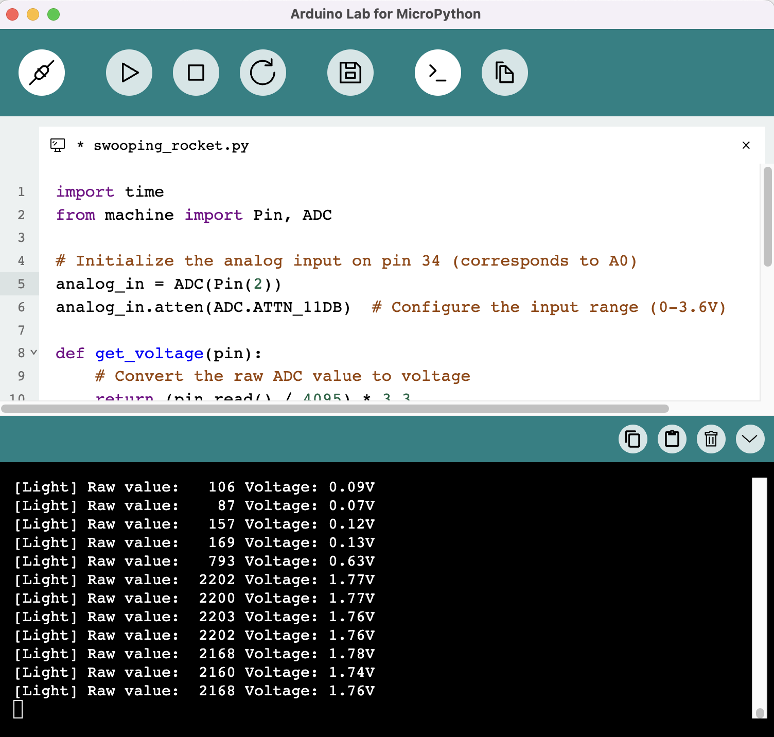
光センサーデータの読み取り
import time
from machine import Pin, ADC

# Initialize the analog input on pin 2 (corresponds to A0)
analog_in = ADC(Pin(2))
analog_in.atten(ADC.ATTN_11DB)  # Configure the input range (0-3.6V)

def get_voltage(pin):
    # Convert the raw ADC value to voltage
    return (pin.read() / 4095) * 3.3

while True:
    # Read the raw analog value
    raw_value = analog_in.read()
    # Convert the raw value to voltage
    voltage = get_voltage(analog_in)

    # Print the raw value and voltage to the serial console
    print("[Light] Raw value: {:5d} Voltage: {:.2f}V".format(raw_value, voltage))

    # Delay for a short period of time before reading again
    time.sleep(1)
OLEDスクリーンを点灯させる
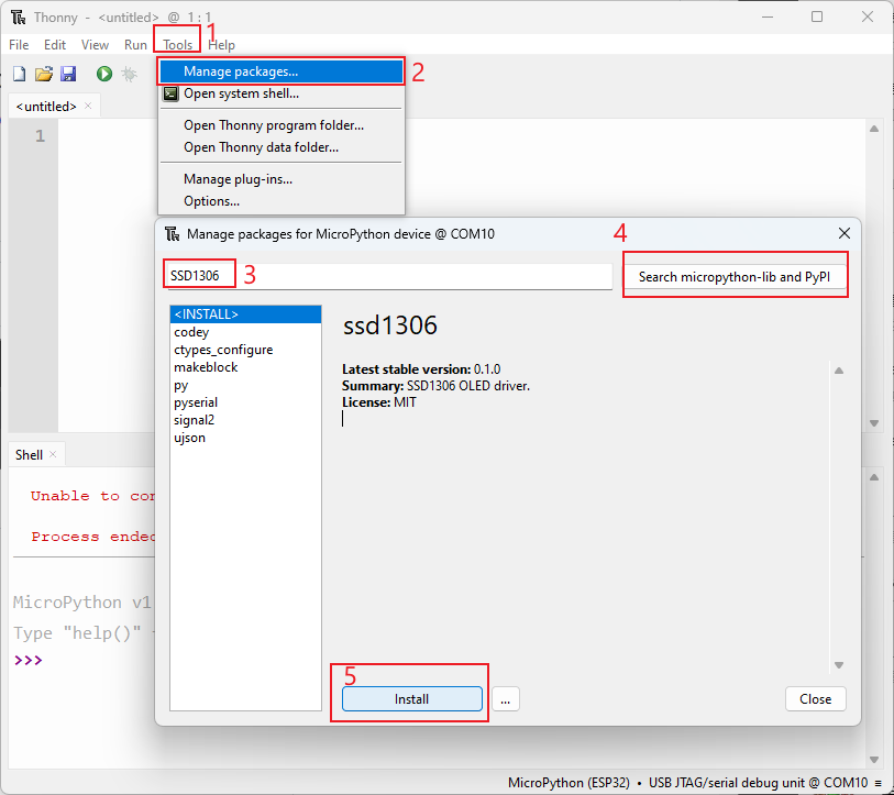
XIAO ESP32C3を接続し、Thonnyを開いて右下をクリックしてインタープリターを設定します インタープリター - Micropython (ESP32) を選択し、ポート >>> OKをクリック
すべてがうまくいけば、シェルに出力が表示されます 必要なライブラリをインストールします 「Tools」をクリック >>> 「Management Packages」をクリック >>> ライブラリ名を入力 >>> 「Search micropython-lib and PyPl」をクリック
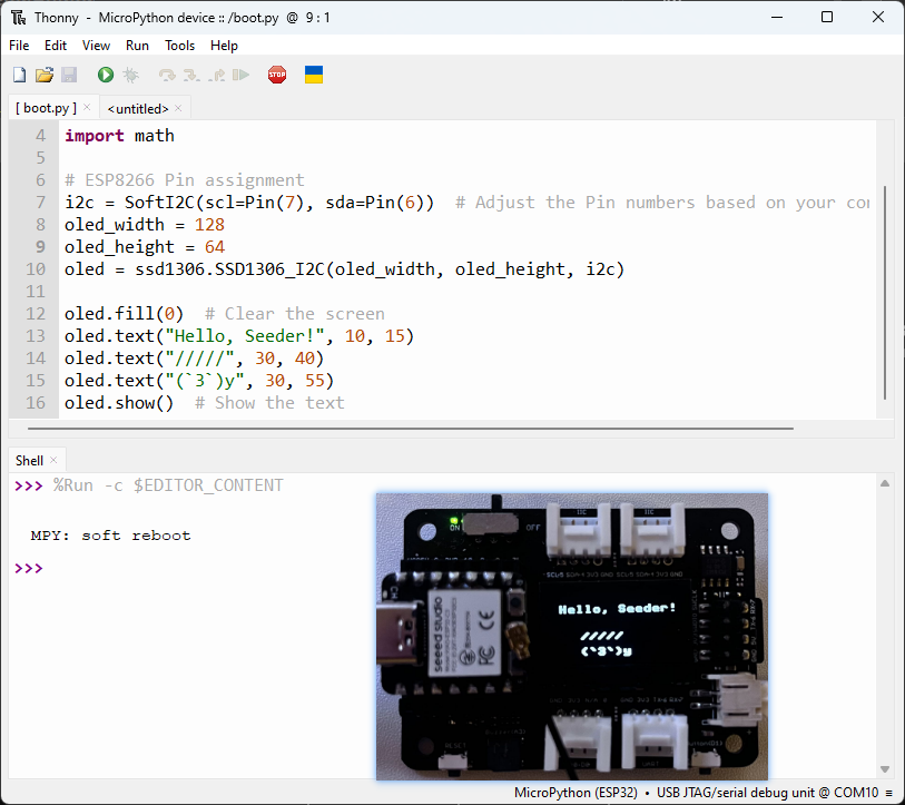
スクリプトを実行してボードにフラッシュします。 コーディングが完了したら、緑色のボタンをクリックしてスクリプトを実行します。
import time
from machine import Pin, SoftI2C
import ssd1306
import math

# Pin assignment
i2c = SoftI2C(scl=Pin(7), sda=Pin(6))  # Adjust the Pin numbers based on your connections
oled_width = 128
oled_height = 64
oled = ssd1306.SSD1306_I2C(oled_width, oled_height, i2c)

oled.fill(0)  # Clear the screen
oled.text("Hello, Seeder!", 10, 15)
oled.text("/////", 30, 40)
oled.text("(`3`)y", 30, 55)
oled.show()  # Show the text
この記事をお読みいただき、ありがとうございました!コメントでご意見をお聞かせください。
リソース
- MicroPythonを搭載したXIAO ESP32C3用のファームウェアバイナリファイル
技術サポート & 製品ディスカッション
弊社製品をお選びいただき、ありがとうございます!弊社では、お客様の製品体験が可能な限りスムーズになるよう、さまざまなサポートを提供しています。異なる好みやニーズに対応するため、複数のコミュニケーションチャンネルをご用意しています。