Seeed Studio XIAO ESP32-C5 でのピン多重化
| Seeed Studio XIAO ESP32-C5 |
|---|
 |
Seeed Studio XIAO ESP32-C5 は、様々な周辺インターフェースと GPIO ピンを備えた強力で多用途な開発ボードです。これらのピンは、他のデバイスとの通信、アナログセンサーの読み取り、LED の制御など、様々な目的に使用できます。このチュートリアルでは、XIAO ESP32-C5 の多重化ピンの使用方法をガイドします。
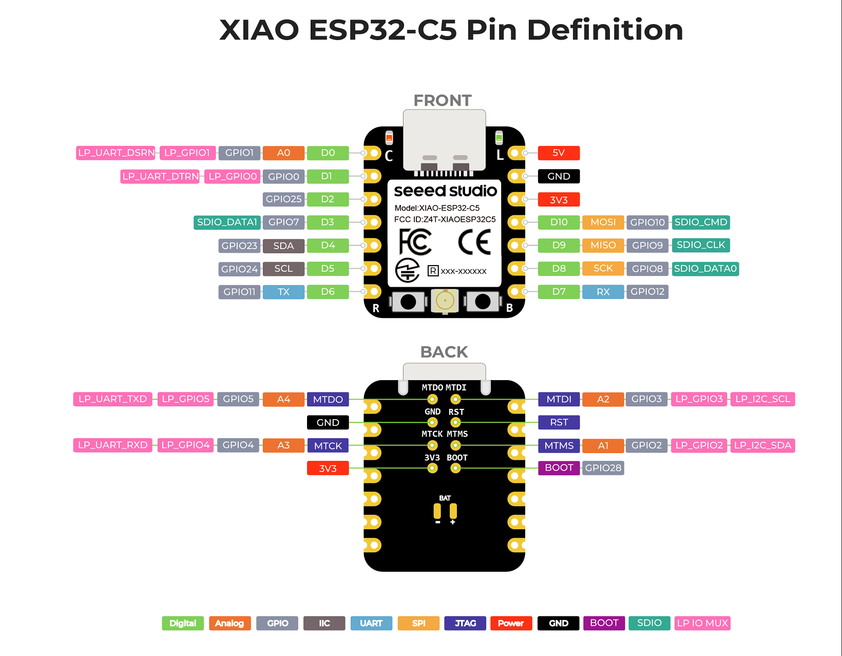
要約すると、XIAO ESP32-C5 は 1×I2C、1×SPI、2×UART、最大 11×GPIO(PWM 対応)、5×ADC チャンネル、および JTAG(裏面のパッド)ボンディングパッドインターフェースを備えています。
入門ガイド
次に、PlatformIO と Arduino IDE の 2 つのプラットフォームに基づいて、それぞれサンプルチュートリアルとコードを提供します。具体的な状況に応じて開発プラットフォームを選択できます。
Arduino IDE を使用したことがない場合は、Seeed Studio XIAO ESP32-C5 入門ガイド を参照してください。
PlatfromIO を使用したことがない場合は、Platform IO with Seeed Studio XIAO ESP32-C5 を参照してください。
ピン配置概要
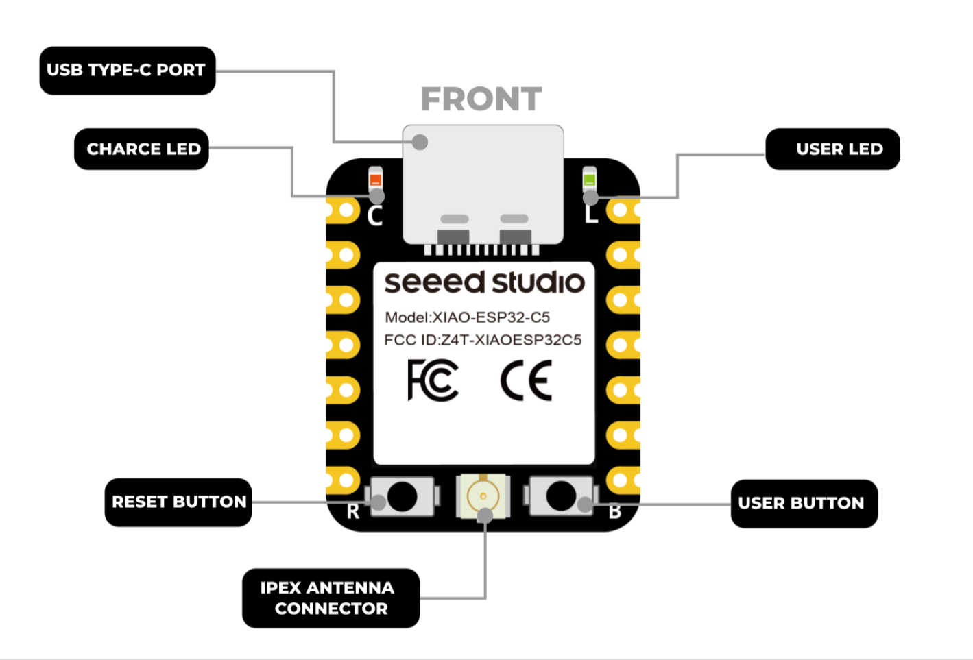
始める前に、XIAO ESP32-C5 が持つすべてのピンとその機能を以下の回路図で確認しましょう。
| XIAO ESP32-C5 表示図 |
|---|
 |
| XIAO ESP32-C5 ピンリスト |
 |
デジタル
XIAO ESP32-C5 の 11 個の IO ピン(D0–D10)はすべてデジタル機能をサポートしています。以下は、デジタル機能を使用してライトのオン/オフ状態を制御する実用的な例で、特定の要件に応じてこれらのピンを多重化できます。
ハードウェア準備
| Seeed Studio XIAO ESP32-C5 | Seeed Studio Grove Base for XIAO | Grove - Variable Color LED | Grove - Button |
|---|---|---|---|
|  |  |  |
ソフトウェア
以下のコード例は Arduino IDE と PlatformIO にそれぞれ基づいており、同じ制御効果を実現します。実際の開発状況に応じて適切なコードを選択して再利用できます。
- Arduino IDE
- PlatformIO
- 参考コード
const int buttonPin = D1;   // Button pin
const int ledPin    = D0;   // LED pin

bool ledState = false;      // LED current state (OFF/ON)

// Debounce
const unsigned long DEBOUNCE_MS = 30;
bool lastReading = HIGH;          // because INPUT_PULLUP idle is HIGH
bool stableState = HIGH;
unsigned long lastChangeTime = 0;

void setup() {
  pinMode(ledPin, OUTPUT);

  pinMode(buttonPin, INPUT_PULLUP);

}

void loop() {
  bool reading = digitalRead(buttonPin);

  // Detect a level change and start timing (for debouncing)
  if (reading != lastReading) {
    lastChangeTime = millis();
    lastReading = reading;
  }

  if (millis() - lastChangeTime >= DEBOUNCE_MS) {
    if (stableState != reading) {
      stableState = reading;


      if (stableState == LOW) {
        ledState = !ledState;                 // toggle
        digitalWrite(ledPin, ledState ? HIGH : LOW);
      }
    }
  }
}
platform.iniの内容が以下のようになっていることを確認してください。
[env:seeed-xiao-esp32-c5]
platform = Seeed Studio
board = seeed-xiao-esp32-c5
framework = arduino
- 参考コード
#include <Arduino.h>

const int buttonPin = D1;   // Button pin
const int ledPin    = D0;   // LED pin

bool ledState = false;      // LED current state (OFF/ON)

// Debounce
const unsigned long DEBOUNCE_MS = 30;
bool lastReading = HIGH;          // because INPUT_PULLUP idle is HIGH
bool stableState = HIGH;
unsigned long lastChangeTime = 0;

void setup() {
  pinMode(ledPin, OUTPUT);

  pinMode(buttonPin, INPUT_PULLUP);

}

void loop() {
  bool reading = digitalRead(buttonPin);

  // Detect a level change and start timing (for debouncing)
  if (reading != lastReading) {
    lastChangeTime = millis();
    lastReading = reading;
  }

  if (millis() - lastChangeTime >= DEBOUNCE_MS) {
    if (stableState != reading) {
      stableState = reading;


      if (stableState == LOW) {
        ledState = !ledState;                 // toggle
        digitalWrite(ledPin, ledState ? HIGH : LOW);
      }
    }
  }
}
結果
- コードをアップロードした後、ボタンを押してください。押すたびに LED がオン/オフを切り替え、実際のライト制御効果をシミュレートします。
ボタンを押しても上記の効果が得られない場合は、まずオンボードの RESET ボタンを押してボードを起動する必要があるかもしれません。
PWM
XIAO ESP32-C5 のピン D0–D11 はすべて PWM 機能をサポートしています。PWM は、サーボ、モーター、LED ライトなどのデバイスを駆動するために使用できます。以下は、PWM の機能を実証する PWM 制御ブリージングライトの例です。
ハードウェア準備
| Seeed Studio XIAO ESP32-C5 | Seeed Studio Grove Base for XIAO | Grove - Variable Color LED |
|---|---|---|
| | |
ソフトウェア
以下のコード例は、それぞれArduino IDEとPlatformIOに基づいており、同じ制御効果を実現します。実際の開発状況に応じて適切なコードを選択して再利用できます。
- Arduino IDE
- PlatformIO
- 参考コード
int ledPin = D1;    // LED connected to digital pin 10

void setup() {
  // declaring LED pin as output
  pinMode(ledPin, OUTPUT);
}

void loop() {
  // fade in from min to max in increments of 5 points:
  for (int fadeValue = 0 ; fadeValue <= 255; fadeValue += 5) {
    // sets the value (range from 0 to 255):
    analogWrite(ledPin, fadeValue);
    // wait for 30 milliseconds to see the dimming effect
    delay(30);
  }

  // fade out from max to min in increments of 5 points:
  for (int fadeValue = 255 ; fadeValue >= 0; fadeValue -= 5) {
    // sets the value (range from 0 to 255):
    analogWrite(ledPin, fadeValue);
    // wait for 30 milliseconds to see the dimming effect
    delay(30);
  }
}
platform.iniの内容が以下のようになっていることを確認してください。
[env:seeed-xiao-esp32-c5]
platform = Seeed Studio
board = seeed-xiao-esp32-c5
framework = arduino
- 参考コード
#include <Arduino.h>

int ledPin = D0;    // LED connected to digital pin 10

void setup() {
  // declaring LED pin as output
  pinMode(ledPin, OUTPUT);
}

void loop() {
  // fade in from min to max in increments of 5 points:
  for (int fadeValue = 0 ; fadeValue <= 255; fadeValue += 5) {
    // sets the value (range from 0 to 255):
    analogWrite(ledPin, fadeValue);
    // wait for 30 milliseconds to see the dimming effect
    delay(30);
  }

  // fade out from max to min in increments of 5 points:
  for (int fadeValue = 255 ; fadeValue >= 0; fadeValue -= 5) {
    // sets the value (range from 0 to 255):
    analogWrite(ledPin, fadeValue);
    // wait for 30 milliseconds to see the dimming effect
    delay(30);
  }
}
結果
コードをアップロードした後、Grove - Variable Color LEDがブリージング(呼吸)ライト効果を表示します。
アナログ
XIAO ESP32-C5では、ピンA0〜A5がアナログ読み取り機能をサポートしています。ADC読み取りは、バッテリー電圧の測定やロータリーエンコーダーの読み取りなどのシナリオに適用できます。次に、Grove-Rotary Angle Sensorの電圧測定を例に、ADC読み取り機能をデモンストレーションします。
ハードウェア準備
| Seeed Studio XIAO ESP32-C5 | Seeed Studio Grove Base for XIAO | Grove - Rotary Angle Sensor |
|---|---|---|
| |  |
ソフトウェア
以下のコード例は、それぞれArduino IDEとPlatformIOに基づいており、同じ制御効果を実現します。実際の開発状況に応じて適切なコードを選択して再利用できます。
- Arduino IDE
- PlatformIO
iconst int analogPin = A0;

void setup() {
  // Initialize serial communication at 115200 bits per second
  Serial.begin(115200);

  // Set the resolution to 12 bits (0-4095)
  analogReadResolution(12);
}

void loop() {
  // Read the analog value and millivolts for the analogPin
  int analogValue = analogRead(analogPin);
  int analogVolts = analogReadMilliVolts(analogPin);

  // Convert millivolts to volts
  float voltage = analogVolts / 1000.0;

  // Print the values to the Serial Monitor
  Serial.printf("ADC analog value = %d\n", analogValue);
  Serial.printf("ADC millivolts value = %d\n", analogVolts);
  Serial.printf("Voltage = %.3f V\n", voltage);

  delay(1000); // Delay for clear reading from serial
}
platform.iniの内容が以下のようになっていることを確認してください。
[env:seeed-xiao-esp32-c5]
platform = Seeed Studio
board = seeed-xiao-esp32-c5
framework = arduino
- 参考コード
#include <Arduino.h>

iconst int analogPin = A0;

void setup() {
  // Initialize serial communication at 115200 bits per second
  Serial.begin(115200);

  // Set the resolution to 12 bits (0-4095)
  analogReadResolution(12);
}

void loop() {
  // Read the analog value and millivolts for the analogPin
  int analogValue = analogRead(analogPin);
  int analogVolts = analogReadMilliVolts(analogPin);

  // Convert millivolts to volts
  float voltage = analogVolts / 1000.0;

  // Print the values to the Serial Monitor
  Serial.printf("ADC analog value = %d\n", analogValue);
  Serial.printf("ADC millivolts value = %d\n", analogVolts);
  Serial.printf("Voltage = %.3f V\n", voltage);

  delay(1000); // Delay for clear reading from serial
}
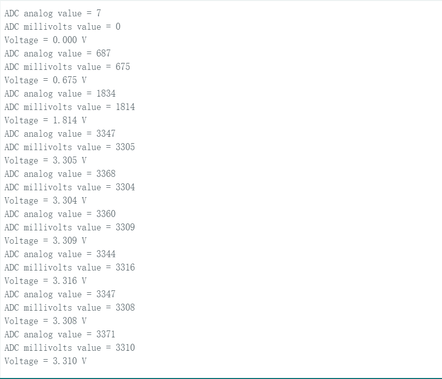
結果
シリアルモニターを開くと、Grove-Rotary Angle Sensorから読み取った生のADC値(analogValue)、ミリボルト値(analogVolts)、電圧値(voltage)が印刷されます。Grove-Rotary Angle Sensorを回転させると明らかな変化が発生します。
シリアル通信
XIAO ESP32-C5は、USB SerialとUART1 Serialの2つのハードウェアシリアル通信インターフェースを備えており、シリアル通信に利用できます。さらに、他の汎用ピンを使用してシリアル通信インターフェースをシミュレートすることもできます。
USB / UART1 Serial
USB Serialの場合、ボードをUSB-C経由で直接コンピューターに接続してモニタリングします。これは前の例で使用されたインターフェースです。UART1 Serialの場合、モニタリングにはSeeed Studio XIAO Debug Mateを使用します。
ハードウェア準備

ソフトウェア
以下のコード例は、それぞれArduino IDEとPlatformIOに基づいており、同じ制御効果を実現します。実際の開発状況に応じて適切なコードを選択して再利用できます。
Serial1の対応ピンはRX_PIN - D7とTX_PIN - D6です。
- Arduino IDE
- PlatformIO
- 参考コード
#define RX_PIN D7
#define TX_PIN D6
#define BAUD 115200

void setup() {
    Serial.begin(115200);
    Serial1.begin(BAUD,SERIAL_8N1,RX_PIN,TX_PIN);
}

void loop() {
    Serial.print("PC Serial \n");
    Serial1.print("Hello XIAO ESP32-C5\n");
  delay(1000);
}
- platform.iniの内容が以下のようになっていることを確認してください。
[env:seeed-xiao-esp32-c5]
platform = Seeed Studio
board = seeed-xiao-esp32-c5
framework = arduino
- 参考コード
#include <Arduino.h>

#define RX_PIN D7
#define TX_PIN D6
#define BAUD 115200

void setup() {
    Serial.begin(115200);
    Serial1.begin(BAUD,SERIAL_8N1,RX_PIN,TX_PIN);
}

void loop() {
    Serial.print("PC Serial \n");
    Serial1.print("Hello XIAO ESP32-C5\n");
  delay(1000);
}
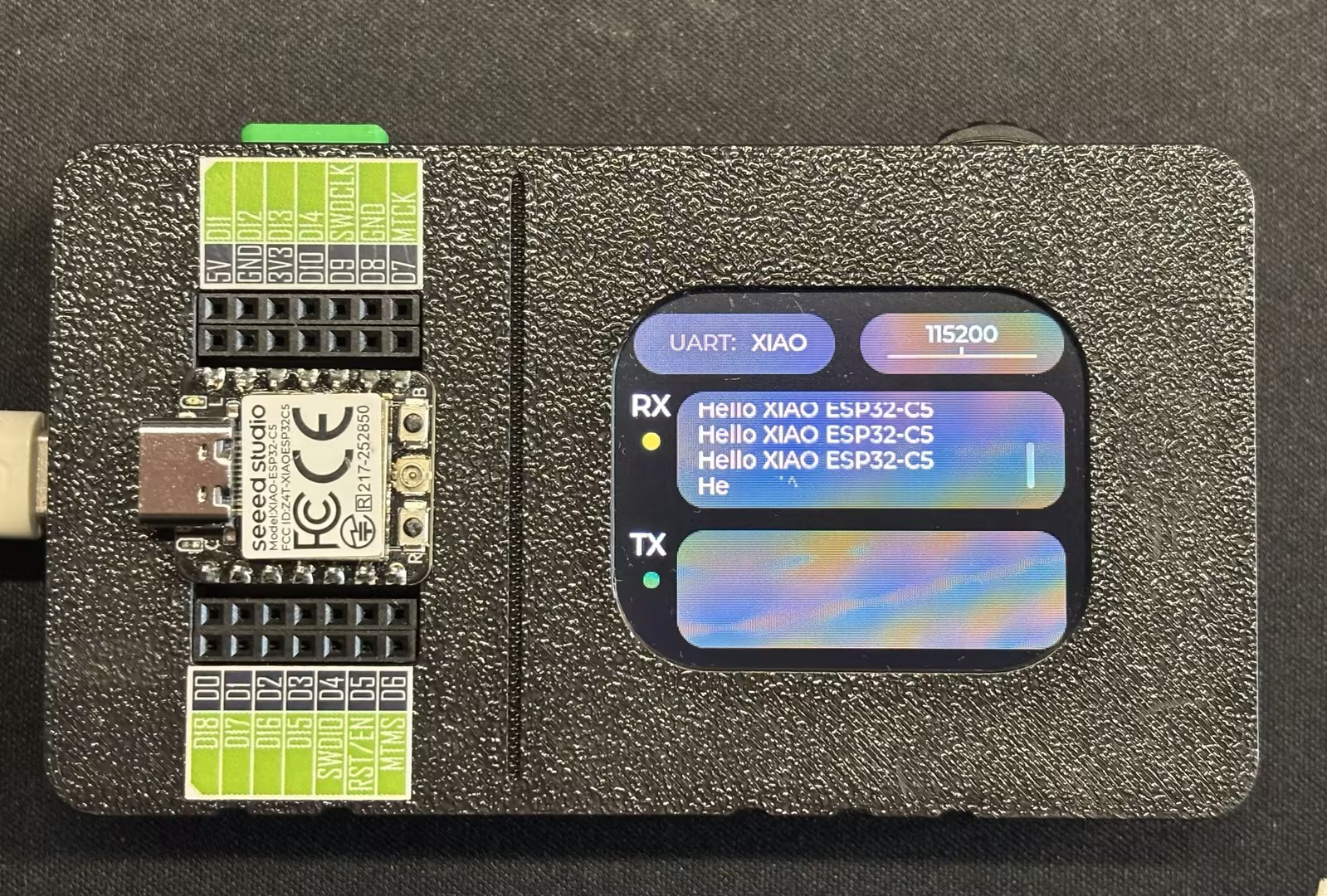
結果
プログラムをアップロードした後、Seeed Studio XIAO Debug Mate の UART 機能を使用して監視できます。
Seeed Studio XIAO Debug Mate を以前に使用したことがない場合は、Getting Started with XIAO Debug Mate をご覧ください。
ソフトウェアシリアル
このセクションでは、汎用ピンを使用してシリアル通信ピンをシミュレートすることで、ソフトウェアシリアル通信の機能を実演します。
ハードウェア準備

ソフトウェア
以下のコード例は、それぞれ Arduino IDE と PlatformIO に基づいており、同じ制御効果を実現します。実際の開発状況に応じて適切なコードを選択して再利用できます。
対応するソフトウェアシミュレートピンは RX_PIN - D2 と TX_PIN - D1 です。
- Arduino IDE
- PlatformIO
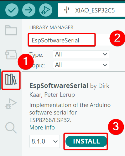
EspSoftwareSerial依存ライブラリをインストールします。
- 参考コード
#include <SoftwareSerial.h>

#define MYPORT_TX D1
#define MYPORT_RX D2

EspSoftwareSerial::UART mySerial;

String receivedData = "";  // Used for storing the received data
unsigned long lastReceiveTime = 0;  // Record the last reception time
const unsigned long TIMEOUT = 100;  // 100ms timeout period

void setup() {
  Serial.begin(115200); //USB-C
  mySerial.begin(38400, SWSERIAL_8N1, MYPORT_RX, MYPORT_TX, false);
}

void loop() {
  // Process the data received via the serial port of the software
  while (mySerial.available()) {
    char incomingChar = mySerial.read();
    receivedData += incomingChar;
    lastReceiveTime = millis();  // The latest time of reception
  }

  // Check if the time limit has been exceeded. If it has, consider that the reception of one frame of data is complete.
  if (receivedData.length() > 0 && (millis() - lastReceiveTime > TIMEOUT)) {
    Serial.print("Received via software serial: ");
    Serial.println(receivedData);
    receivedData = "";  // Clear the buffer area
  }

  // Process the data received through the hardware serial port
  if (Serial.available()) {
    String data = Serial.readString();  // Read the entire string at once
    mySerial.print("Received via hardware serial: ");
    mySerial.println(data);
  }
}
platform.iniの内容が以下のようになっていることを確認してください。
[env:seeed-xiao-esp32-c5]
platform = Seeed Studio
board = seeed-xiao-esp32-c5
framework = arduino
lib_deps = plerup/EspSoftwareSerial@^8.2.0
- 参考コード
#include <Arduino.h>
#include <SoftwareSerial.h>

#define MYPORT_TX D1
#define MYPORT_RX D2

EspSoftwareSerial::UART mySerial;

String receivedData = "";  // Used for storing the received data
unsigned long lastReceiveTime = 0;  // Record the last reception time
const unsigned long TIMEOUT = 100;  // 100ms timeout period

void setup() {
  Serial.begin(115200); //USB-C
  mySerial.begin(38400, SWSERIAL_8N1, MYPORT_RX, MYPORT_TX, false);
}

void loop() {
  // Process the data received via the serial port of the software
  while (mySerial.available()) {
    char incomingChar = mySerial.read();
    receivedData += incomingChar;
    lastReceiveTime = millis();  // The latest time of reception
  }

  // Check if the time limit has been exceeded. If it has, consider that the reception of one frame of data is complete.
  if (receivedData.length() > 0 && (millis() - lastReceiveTime > TIMEOUT)) {
    Serial.print("Received via software serial: ");
    Serial.println(receivedData);
    receivedData = "";  // Clear the buffer area
  }

  // Process the data received through the hardware serial port
  if (Serial.available()) {
    String data = Serial.readString();  // Read the entire string at once
    mySerial.print("Received via hardware serial: ");
    mySerial.println(data);
  }
}
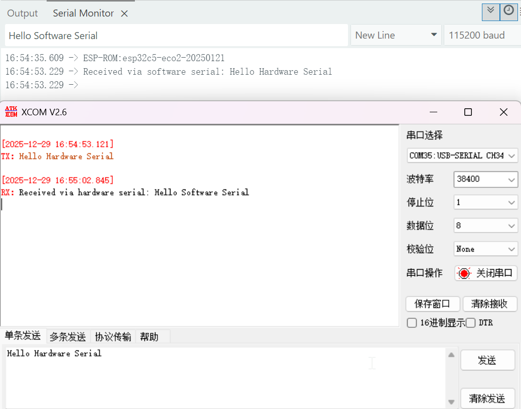
結果
- 配線図
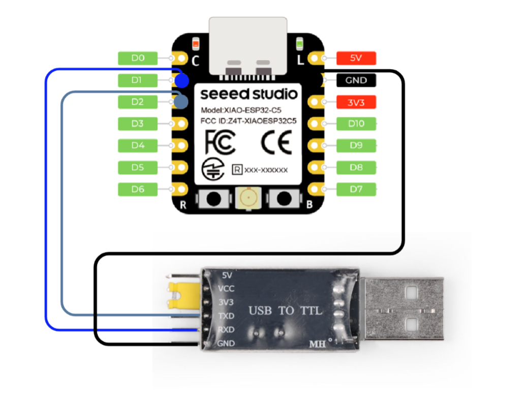
- プログラムをアップロードした後、ボードを任意のシリアルツールに接続し、対応するボーレートを設定すると、双方向通信を確立できます。
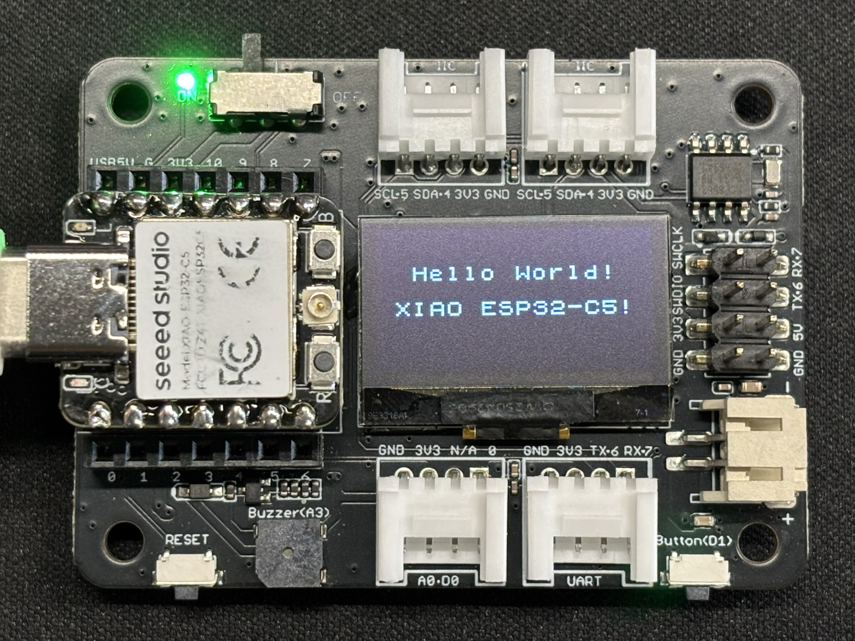
I2C
XIAO ESP32-C5 チップは I2C インターフェースを統合しており、フラッシュメモリ、ディスプレイ、センサーなどの外部 I2C デバイスの接続に使用できます。次に、Seeed Studio Expansion Board Base for XIAO を例として I2C の使用方法を実演します。
ハードウェア準備

ソフトウェア
以下のコード例は、それぞれ Arduino IDE と PlatformIO に基づいており、同じ表示効果を実現します。実際の開発シナリオに応じて適切なコードを選択して再利用できます。
- Arduino IDE
- PlatformIO
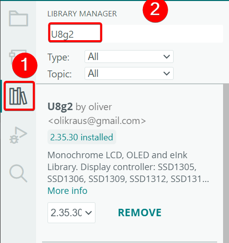
- U8g2 ライブラリをインストールします。
- 参考コード
#include <U8x8lib.h>
#include <Wire.h>

#define SCL D5
#define SDA D4

U8X8_SSD1306_128X64_NONAME_HW_I2C u8x8(/* clock=*/ SCL, /* data=*/ SDA, /* reset=*/ U8X8_PIN_NONE);   // OLEDs without Reset of the Display

void setup(void) {
  u8x8.begin();
  u8x8.setFlipMode(0);
}

void loop(void) {
  u8x8.setFont(u8x8_font_chroma48medium8_r);

  u8x8.setCursor(2, 10);
  u8x8.print("Hello World!");
  u8x8.setCursor(1, 28);
  u8x8.print("XIAO ESP32-C5!");
}
platform.iniの内容が以下のようになっていることを確認してください。
[env:seeed-xiao-esp32-c5]
platform = Seeed Studio
board = seeed-xiao-esp32-c5
framework = arduino
lib_deps =
	olikraus/U8g2@^2.36.15
- 参考コード
#include <Arduino.h>
#include <U8x8lib.h>
#include <Wire.h>

#define SCL D5
#define SDA D4

U8X8_SSD1306_128X64_NONAME_HW_I2C u8x8(/* clock=*/ SCL, /* data=*/ SDA, /* reset=*/ U8X8_PIN_NONE);   // OLEDs without Reset of the Display

void setup(void) {
  u8x8.begin();
  u8x8.setFlipMode(0);
}

void loop(void) {
  u8x8.setFont(u8x8_font_chroma48medium8_r);

  u8x8.setCursor(2, 10);
  u8x8.print("Hello World!");
  u8x8.setCursor(1, 28);
  u8x8.print("XIAO ESP32-C5!");
}
結果
- プログラムをアップロードした後、画面に
Hello World!とXIAO ESP32-C5!のテキストが表示されます。
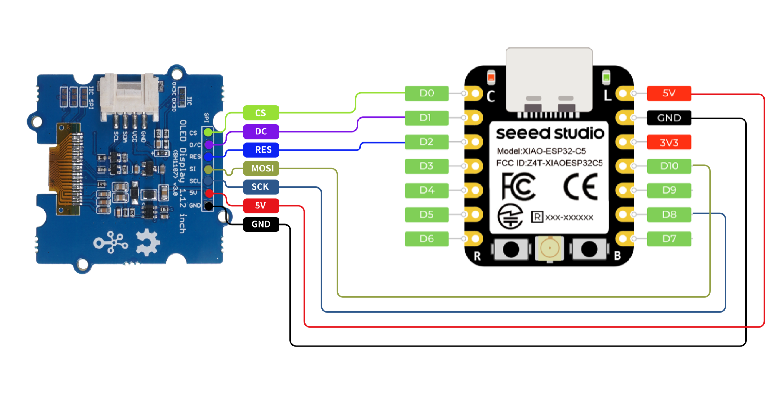
SPI
XIAO ESP32-C5 チップは SPI インターフェースを統合しており、フラッシュメモリ、ディスプレイ、センサーなどの外部 SPI デバイスの接続に使用できます。この例では、SPI 画面を使用して SPI の機能を実演します。
ハードウェア準備

ソフトウェア
以下のコードスニペットは、それぞれArduino IDEとPlatformIOに基づいており、同じ表示効果を実現します。実際の開発ニーズに応じて適切なコードを選択して再利用できます。
- Arduino IDE
- PlatformIO
- U8g2ライブラリをインストールします。
- 参考コード
#include <U8g2lib.h>
#include <SPI.h>
#include <Wire.h>

U8G2_SH1107_128X128_1_4W_HW_SPI u8g2(U8G2_R3,
  /* cs=*/    D0,
  /* dc=*/    D1,
  /* reset=*/ D2);

void setup(void) {
  u8g2.begin();
}

void loop(void) {
  const char* msg = "Hello XIAO ESP32-C5";

  u8g2.firstPage();
  do {
    u8g2.setFont(u8g2_font_luBIS08_tf);

    int16_t w = u8g2.getStrWidth(msg);
    int16_t x = (128 - w) / 2;

    int16_t ascent  = u8g2.getAscent();
    int16_t descent = u8g2.getDescent();
    int16_t h = ascent - descent;
    int16_t y = (128 - h) / 2 + ascent;

    u8g2.drawStr(x, y, msg);
  } while (u8g2.nextPage());
}
platform.iniの内容が以下のようになっていることを確認してください。
[env:seeed-xiao-esp32-c5]
platform = Seeed Studio
board = seeed-xiao-esp32-c5
framework = arduino
lib_deps =
  olikraus/U8g2@^2.36.15
- 参考コード
#include <Arduino.h>
#include <U8g2lib.h>
#include <SPI.h>
#include <Wire.h>

U8G2_SH1107_128X128_1_4W_HW_SPI u8g2(U8G2_R3,
  /* cs=*/    D0,
  /* dc=*/    D1,
  /* reset=*/ D2);

void setup(void) {
  u8g2.begin();
}

void loop(void) {
  const char* msg = "Hello XIAO ESP32-C5";

  u8g2.firstPage();
  do {
    u8g2.setFont(u8g2_font_luBIS08_tf);

    int16_t w = u8g2.getStrWidth(msg);
    int16_t x = (128 - w) / 2;

    int16_t ascent  = u8g2.getAscent();
    int16_t descent = u8g2.getDescent();
    int16_t h = ascent - descent;
    int16_t y = (128 - h) / 2 + ascent;

    u8g2.drawStr(x, y, msg);
  } while (u8g2.nextPage());
}
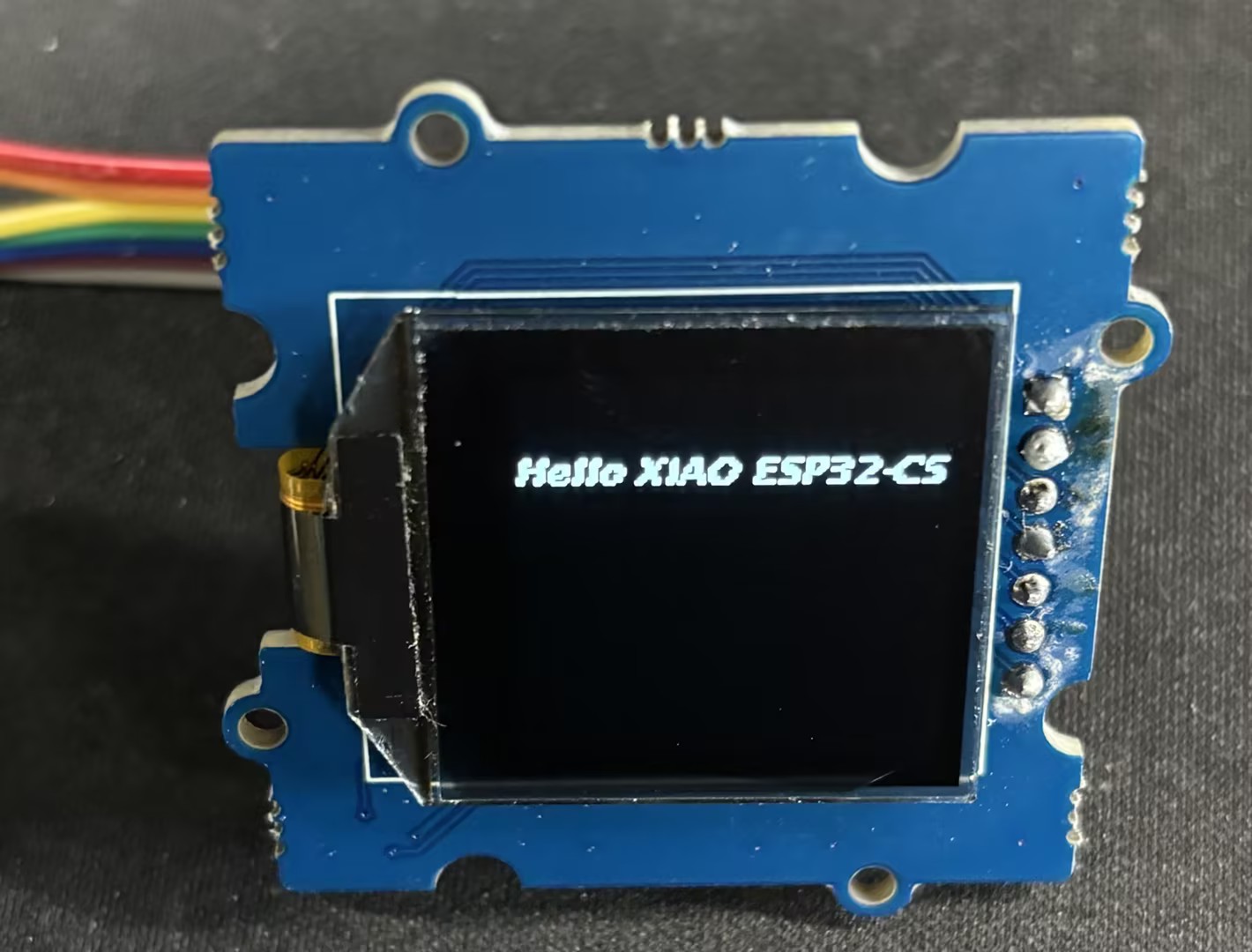
結果
- 配線図
- コードをアップロードした後、画面に「Hello XIAO ESP32-C5」のテキストが表示されます。
技術サポート & 製品ディスカッション
弊社製品をお選びいただき、ありがとうございます!弊社製品での体験が可能な限りスムーズになるよう、さまざまなサポートを提供しています。異なる好みやニーズに対応するため、複数のコミュニケーションチャンネルを用意しています。