Seeed Studio XIAO ESP32C5 Zigbee クイックスタートガイド (Arduino)
このチュートリアルでは、Seeed Studio XIAO ESP32-C5 開発ボードで Zigbee アプリケーションを実装する方法をガイドします。このボードは Wi-Fi、Bluetooth Low Energy (BLE)、Zigbee 接続を組み合わせており、IoT アプリケーション に最適です。このガイドの例では、esp-arduino Zigbee SDK を使用して Zigbee 機能を実現します。
Arduino IDE の準備がまだの場合は、入門ガイド を参照してください。
Zigbee 概要
Zigbee は IEEE 802.15.4 標準に基づく 低消費電力、低帯域幅 のワイヤレス通信プロトコルです。ホームオートメーション、スマートシティ、産業制御 などの IoT シナリオに特化しており、動的環境での信頼性の高い通信のための堅牢なメッシュネットワーク機能を提供します。
- Zigbee 関連の内容について簡単に説明します。アプリケーション例を直接参照したい場合は、先に進むこともできます。
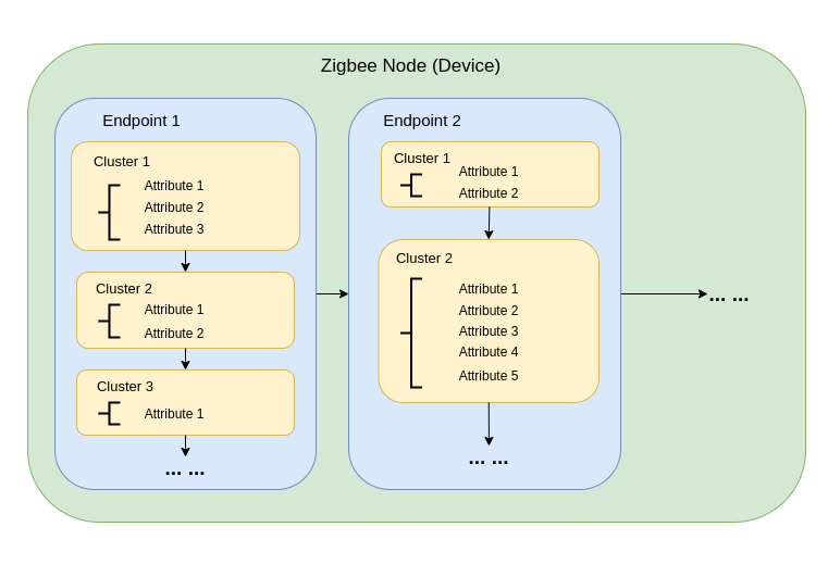
Zigbee データモデル
Zigbee 通信は Zigbee Cluster Library (ZCL) に依存しており、デバイスがその機能をどのように整理し、相互作用するかを定義します。主要なコンポーネントには以下が含まれます:
-
デバイスタイプ Zigbee デバイス(スイッチ、センサー、ライトなど)は特定の動作で事前定義されており、機能的な クラスター にグループ化されています。
-
クラスター クラスターは以下の論理的なグループです:
- 属性:明度や温度などのデバイス状態を表します。
- コマンド:ライトをオンにしたり、明度を50%に設定するなどのアクションをトリガーします。
例:
- On/Off クラスター:電源などのバイナリ状態を制御します。
- Level Control クラスター:強度や明度を調整します。
- Temperature Measurement クラスター:温度測定値を送信します。
- Scenes クラスター:プリセット設定を保存・呼び出しします。
-
属性とコマンド 属性はデバイスデータ(状態、設定など)を保存し、コマンドはアクションを開始します。
Zigbee ネットワークアーキテクチャ
Zigbee ネットワークは3つの主要なノードタイプで構成されます:
-
Zigbee コーディネーター (ZC)
- ネットワークの中央ハブとして機能します。
- ネットワークの作成、デバイス認証、アドレス割り当てを処理します。
- ネットワークの初期化と管理を担当します。
- 各 Zigbee ネットワークには 1つのコーディネーター のみ存在できます。
-
Zigbee ルーター (ZR)
- デバイス間でメッセージを中継してネットワーク範囲を拡張します。
- 追加デバイスのネットワーク参加をサポートします。
- 通常は主電源で動作し、継続的な動作と信頼性の高いメッセージ中継を確保します。
- バッテリー駆動のルーターも可能ですが、エネルギー需要が高いため一般的ではありません。
-
Zigbee エンドデバイス (ZED)
- 親ノード(コーディネーターまたはルーター)と通信する軽量で電力効率の良いデバイスです。
- 他のデバイスにメッセージをルーティングしません。
- バッテリー動作に最適化されており、通常はエネルギー節約のためスリープモードに入ります。
-
アドレッシングとルーティング:
- Zigbee は16ビットアドレッシング方式を使用します。デバイスは直接アドレッシングと間接アドレッシングの組み合わせで通信します。
- ルーティング決定は、AODV(Ad hoc On-demand Distance Vector)などのアルゴリズムを使用してルーターによって行われます。
-
電源管理:
- Zigbee エンドデバイスは低消費電力に最適化されています。多くの場合スリープモードで動作し、必要な時のみ起動します。
- ルーターとコーディネーターは一般的に主電源で動作し、一貫した可用性を確保します。
ネットワークトポロジー
Zigbee は、アプリケーション要件と環境に応じて、3つの主要なネットワークトポロジーをサポートします:
1. メッシュトポロジー
-
1つのコーディネーターと複数のルーターが自己修復可能で堅牢なネットワークを形成します。
-
通信パスが中断された場合、デバイスは動的にメッセージを再ルーティングでき、高い信頼性を確保します。
-
広範囲のカバレッジと冗長性を必要とする大規模ネットワークに最適です。
-
主な特徴:
- 動的再ルーティングにより高い信頼性を確保します。
- スケーラブルなカバレッジで大規模ネットワークをサポートします。
- 自己修復メカニズムにより障害耐性が向上します。
2. ツリートポロジー
-
コーディネーターが階層構造のルートとして機能し、ルーターがブランチを形成します。
-
各ブランチには複数のエンドデバイスや追加のルーターを持つことができ、ツリー状の構造を作成します。
-
通信は階層パスに依存するため、潜在的な単一障害点が発生します。
-
主な特徴:
- 構造化された環境でうまく機能します。
- メッシュネットワークよりもセットアップと管理が簡単です。
- ブランチの障害に脆弱で、サブネットワーク全体が切断される可能性があります。
3. スタートポロジー
-
すべてのデバイスがコーディネーターと直接通信します。
-
展開は簡単ですが、コーディネーターが単一障害点となります。
-
デバイスがコーディネーターの近くに配置されている小規模ネットワークに最適です。
-
主な特徴:
- セットアップと管理が簡単です。
- 範囲とデバイス容量の制約によりスケーラビリティが制限されます。
- すべての通信をコーディネーターに依存するため、障害耐性が低下します。
Arduino Zigbee を始める
Arduino IDE 内で XIAO ESP32-C5 上の Zigbee_On_Off_Light と Zigbee_On_Off_Switch を使用して、Zigbee ネットワーク機能をデモンストレーションします。
ハードウェアの準備
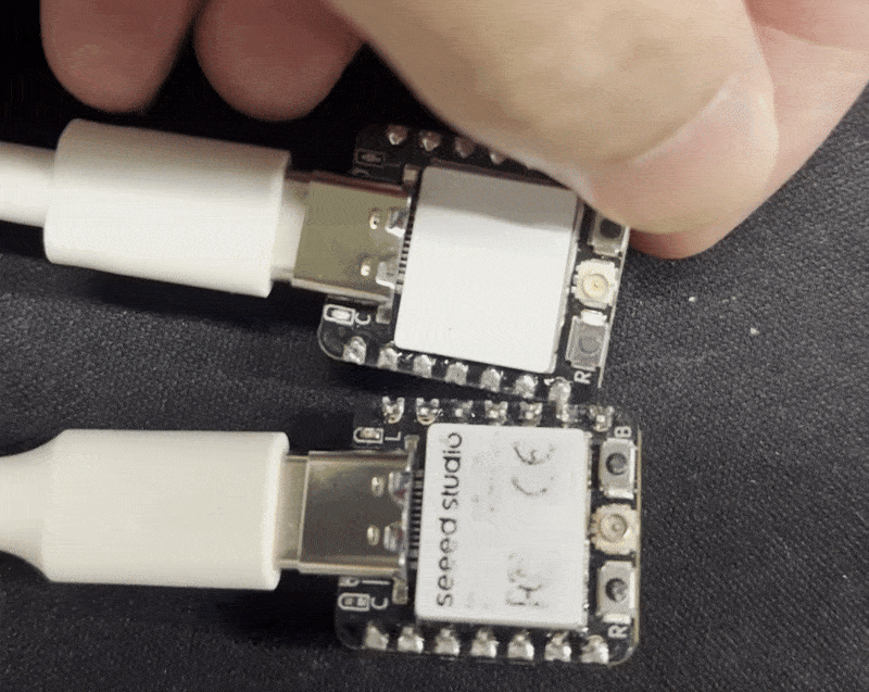
2つの XIAO ESP32-C5 ボードを準備する必要があります。
| Seeed Studio XIAO ESP32-C5 |
|---|
 |
Zigbee_On_Off_Light
1つの XIAO ESP32-C5 を電球デバイスとして選択する必要があります。
ステップ 1. エンドデバイスモードの設定
XIAO ESP32-C5 を Zigbee エンドデバイスとして設定する必要があります。
- Tools -> Zigbee Mode をクリックし、モードを Zigbee ED (End Device) として選択します。
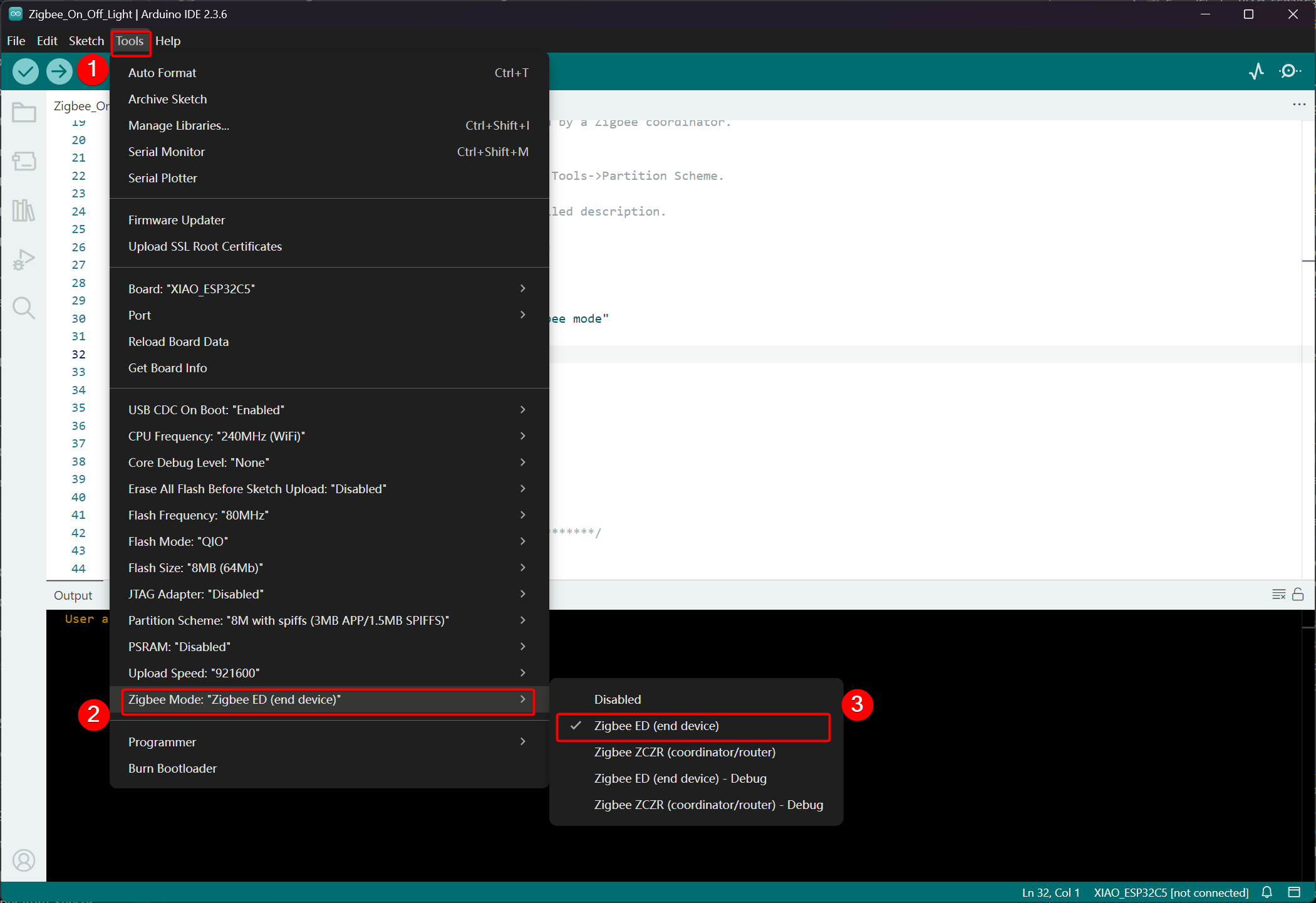
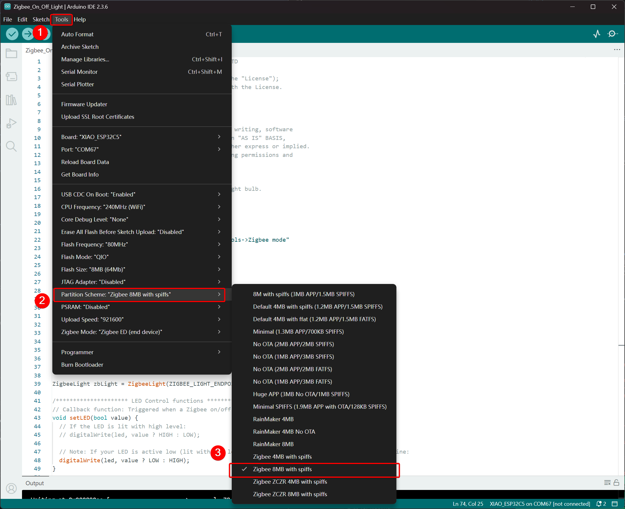
- パーティションスキームを選択し、Tools -> Partition Scheme -> Zigbee 8MB with spiffs に移動します
XIAO ESP32-C5 の FLASH メモリは 8MB です。パーティションスキームを選択する際は、Zigbee 8MB with spiffs を選択することをお勧めします。
ステップ 2. コードの記述
- 公式 Arduino リポジトリを参照して例を取得します。
- または、Arduino IDE のパスから例を選択することもできます:File -> Examples -> Zigbee -> Zigbee_On_Off_Light。

- 例を修正する
XIAO ESP32-C5 では、オンボード LED を発光電球として選択し、制御ピンは GPIO27 です。
Zigbee_On_Off_Light.ino
// Copyright 2024 Espressif Systems (Shanghai) PTE LTD
//
// Licensed under the Apache License, Version 2.0 (the "License");
// you may not use this file except in compliance with the License.
// You may obtain a copy of the License at

//     http://www.apache.org/licenses/LICENSE-2.0
//
// Unless required by applicable law or agreed to in writing, software
// distributed under the License is distributed on an "AS IS" BASIS,
// WITHOUT WARRANTIES OR CONDITIONS OF ANY KIND, either express or implied.
// See the License for the specific language governing permissions and
// limitations under the License.

/**
 * @brief This example demonstrates simple Zigbee light bulb.
 *
 * Modified for Single Color LED control.
 */

#ifndef ZIGBEE_MODE_ED
#error "Zigbee end device mode is not selected in Tools->Zigbee mode"
#endif

#include "Zigbee.h"

/* Zigbee light bulb configuration */
#define ZIGBEE_LIGHT_ENDPOINT 10

// =========================================================
// Modification Area: Define your single-color LED pin here
// If your LED is connected to GPIO 2, set it to 2.
// If using the onboard standard LED, LED_BUILTIN can usually be used
// =========================================================
uint8_t led = 27;  // <--- Please modify the number here to your actual GPIO pin number

uint8_t button = BOOT_PIN;

ZigbeeLight zbLight = ZigbeeLight(ZIGBEE_LIGHT_ENDPOINT);

/********************* LED Control functions **************************/
// Callback function: Triggered when a Zigbee on/off command is received
void setLED(bool value) {
  // If the LED is lit with high level:
  // digitalWrite(led, value ? HIGH : LOW);

  // Note: If your LED is active low (lit with low level), use the line below instead of the above line:
  digitalWrite(led, value ? LOW : HIGH);
}

/********************* Arduino functions **************************/
void setup() {
  Serial.begin(115200);

  // Initialize LED pin as output mode
  pinMode(led, OUTPUT);
  // Turn off LED by default (assuming low level means on)
  digitalWrite(led, LOW);

  // Initialize button for factory reset
  pinMode(button, INPUT_PULLUP);

  // Optional: Set Zigbee device name and model (will be displayed in Home Assistant)
  zbLight.setManufacturerAndModel("Espressif", "SingleColorLight");

  // Set callback function for light state change
  zbLight.onLightChange(setLED);

  // Add Endpoint to Zigbee core
  Serial.println("Adding ZigbeeLight endpoint to Zigbee Core");
  Zigbee.addEndpoint(&zbLight);

  // Start Zigbee
  if (!Zigbee.begin()) {
    Serial.println("Zigbee failed to start!");
    Serial.println("Rebooting...");
    ESP.restart();
  }
  Serial.println("Connecting to network");
  while (!Zigbee.connected()) {
    Serial.print(".");
    delay(100);
  }
  Serial.println();
}

void loop() {
  // Check button for factory reset
  if (digitalRead(button) == LOW) {  // Button is pressed
    // Button debounce
    delay(100);
    int startTime = millis();
    while (digitalRead(button) == LOW) {
      delay(50);
      if ((millis() - startTime) > 3000) {
        // If pressed for more than 3 seconds, reset Zigbee and reboot
        Serial.println("Resetting Zigbee to factory and rebooting in 1s.");
        delay(1000);
        Zigbee.factoryReset();
      }
    }
    // Short press of the button: Toggle light state (local control)
    zbLight.setLight(!zbLight.getLightState());
  }
  delay(100);
}
- コードをアップロードします。 デフォルトでローレベルでオンに設定されているため、コードをアップロード後にリセットボタンを押すと、オンボード LED が点灯します。
実装ロジック
- モードチェック
#ifndef ZIGBEE_MODE_ED
#error "Zigbee end device mode is not selected..."
#endif
これにより、Arduino IDE の Tools → Zigbee mode で "End Device" モードの選択が強制されます。Zigbee 電球は通常、Router や Coordinator ではなく、低電力の End Device として動作します。
- ヘッダーファイルのインクルード
#include "Zigbee.h"
Espressif が提供するコア Zigbee ライブラリをインポートします。これには Zigbee 関連のすべてのクラスと関数が含まれています。
- 設定定義
#define ZIGBEE_LIGHT_ENDPOINT 10
Zigbee エンドポイント番号を 10 として定義します。Zigbee デバイスは複数のエンドポイントを持つことができ、ここでは電球機能がエンドポイント 10 に割り当てられています。
- ユーザー変更可能エリア(最も重要な部分)
uint8_t led = 27;        // Modify this to the actual GPIO pin connected to your LED
uint8_t button = BOOT_PIN;  // Usually GPIO0, used for factory reset
-
led = 27:単色 LED を制御する GPIO ピンです。ハードウェアの配線に応じてこの番号を変更してください。 -
button = BOOT_PIN:通常は ESP32 開発ボードの BOOT ボタン(GPIO0)で、長押しで Zigbee 設定をリセットするために使用されます。
- Zigbee 電球オブジェクトの作成
ZigbeeLight zbLight = ZigbeeLight(ZIGBEE_LIGHT_ENDPOINT);
標準的な Zigbee HA(Home Automation)OnOff Cluster を実装する Zigbee Light オブジェクトを作成し、リモートでのオン/オフ制御をサポートします。
- LED 制御コールバック関数
void setLED(bool value) {
  digitalWrite(led, value ? LOW : HIGH);
}
この関数は、Zigbee ネットワークからオン/オフコマンドを受信したときに自動的に呼び出されます。
- 現在のコードは、LED が アクティブロー(ESP32 開発ボードの外部 LED が抵抗を介して GND に接続されている場合によくある)であることを前提としています。
- LED がアクティブハイの場合(例:VCC に直接接続され、GPIO をローにプルすることで点灯する場合)、以下のコメント行に変更してください:
digitalWrite(led, value ? HIGH : LOW);
- setup() 関数の詳細説明
void setup() {
  Serial.begin(115200);                    // Enable serial debugging with baud rate 115200

  pinMode(led, OUTPUT);                    // Set the LED pin as output
  digitalWrite(led, LOW);                  // Turn off the LED by default (assuming active low, write LOW to ensure it's off)

  pinMode(button, INPUT_PULLUP);           // Set the button pin as input with pull-up resistor

  zbLight.setManufacturerAndModel("Espressif", "SingleColorLight");
  // Set the device manufacturer and model for friendly display on platforms like Home Assistant

  zbLight.onLightChange(setLED);
  // Key step: Bind the callback function for switch state changes, which calls setLED() when a Zigbee command is received

  Zigbee.addEndpoint(&zbLight);
  // Add the bulb endpoint to the Zigbee core

  if (!Zigbee.begin()) { ... ESP.restart(); }
  // Start the Zigbee stack; restart if it fails

  while (!Zigbee.connected()) { ... }
  // Wait for successful joining of the Zigbee network (pairing completed), print a dot every 100ms
}
- loop() 関数の詳細説明
void loop() {
  if (digitalRead(button) == LOW) {        // Detect button press (low level)
    delay(100);                            // Simple debounce
    int startTime = millis();

    while (digitalRead(button) == LOW) {   // Continuously detect if the button is still pressed
      if ((millis() - startTime) > 3000) { // Long press for more than 3 seconds
        Zigbee.factoryReset();             // Factory reset Zigbee configuration (clear pairing information)
        delay(1000);
        // The device will automatically restart and enter pairing mode again
      }
    }

    // If short press: manually control the light's on/off state locally
    zbLight.setLight(!zbLight.getLightState());
    // This triggers the callback setLED() simultaneously to turn the light on/off locally
  }

  delay(100);
}
Zigbee_On_Off_Switch
別の XIAO ESP32-C5 をスイッチとして選択します。これは前の電球デバイスと Zigbee ネットワークを形成し、電球のオン/オフ状態を制御します。
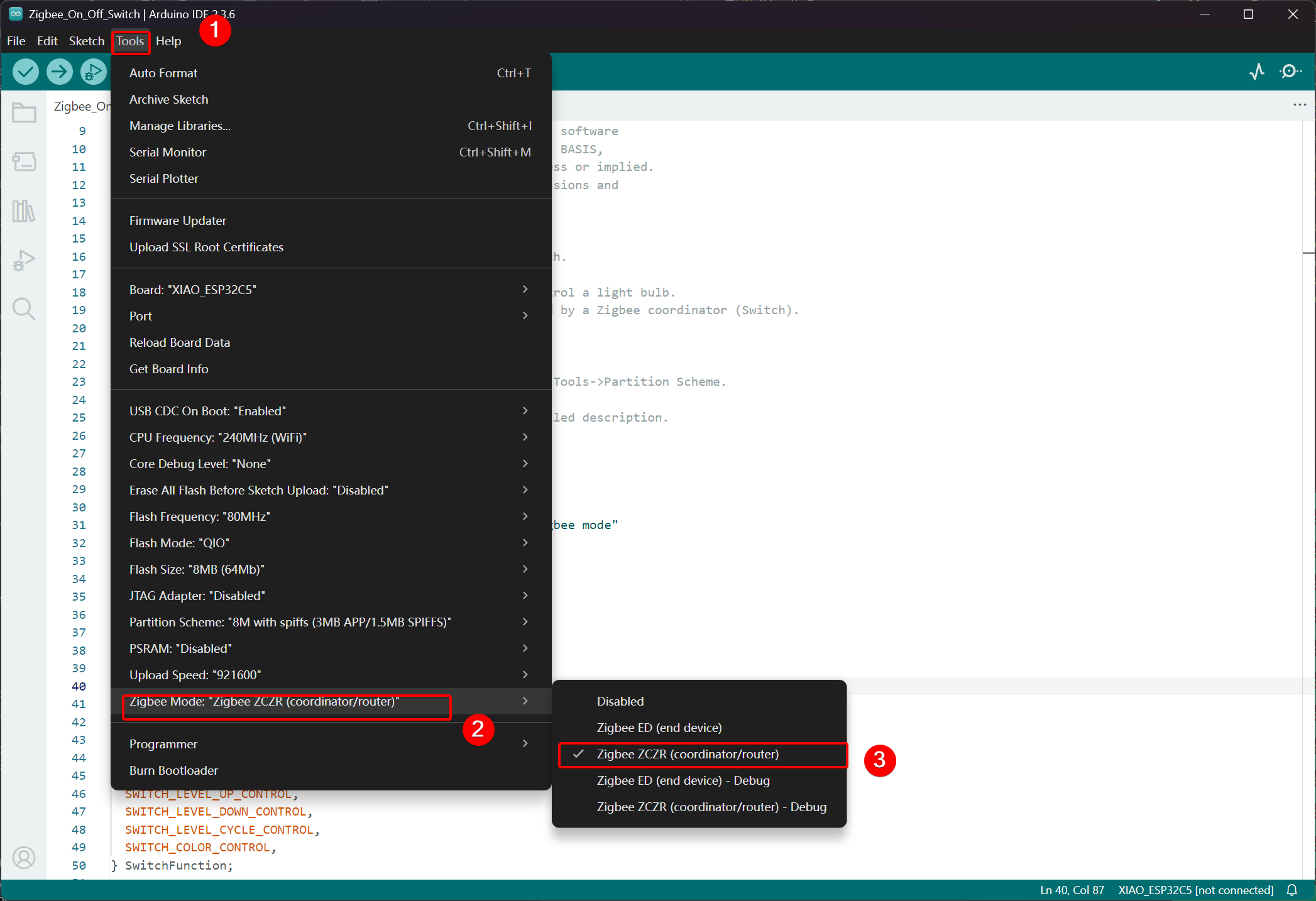
ステップ 1. コーディネーターモードに設定
- Tools -> Zigbee Mode をクリックし、モードを Zigbee ZCZR (Coordinator/Router) として選択します。
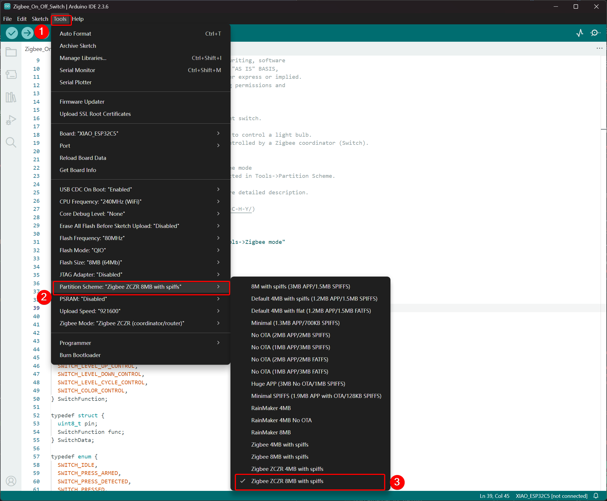
- パーティションスキームを選択し、Tools -> Partition Scheme に移動して Zigbee 8MB ZCZR with spiffs を選択します。
XIAO ESP32-C5 の FLASH メモリは 8MB です。パーティションスキームを選択する際は、Zigbee 8MB ZCZR with spiffs を選択することをお勧めします。
ステップ 2. コードを書く
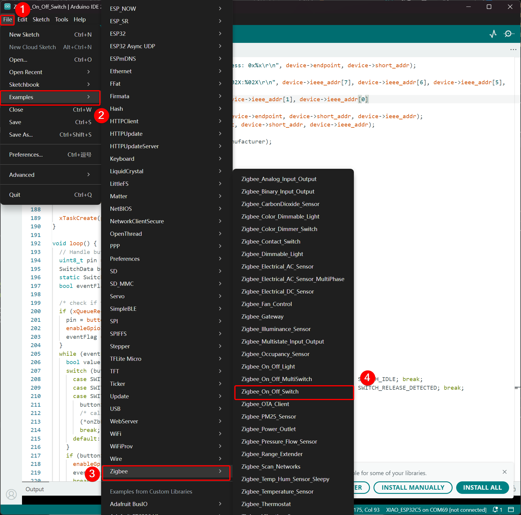
- 公式 Arduino リポジトリにスキップしてサンプルコードを取得します。
- または、Arduino IDE から次のパスでサンプルを選択することもできます:File -> Examples -> Zigbee -> Zigbee_On_Off_Swicth。
- スイッチとして BOOT ボタンを選択します。XIAO ESP32-C5 では、BOOT ボタンは GPIO28 ピンに対応しています。
Zigbee_On_Off_Switch.ino
// Copyright 2024 Espressif Systems (Shanghai) PTE LTD
//
// Licensed under the Apache License, Version 2.0 (the "License");
// you may not use this file except in compliance with the License.
// You may obtain a copy of the License at
//
//     http://www.apache.org/licenses/LICENSE-2.0
//
// Unless required by applicable law or agreed to in writing, software
// distributed under the License is distributed on an "AS IS" BASIS,
// WITHOUT WARRANTIES OR CONDITIONS OF ANY KIND, either express or implied.
// See the License for the specific language governing permissions and
// limitations under the License.

/**
 * @brief This example demonstrates simple Zigbee light switch.
 *
 * The example demonstrates how to use Zigbee library to control a light bulb.
 * The light bulb is a Zigbee end device, which is controlled by a Zigbee coordinator (Switch).
 * Button switch and Zigbee runs in separate tasks.
 *
 * Proper Zigbee mode must be selected in Tools->Zigbee mode
 * and also the correct partition scheme must be selected in Tools->Partition Scheme.
 *
 * Please check the README.md for instructions and more detailed description.
 *
 * Created by Jan Procházka (https://github.com/P-R-O-C-H-Y/)
 */

#ifndef ZIGBEE_MODE_ZCZR
#error "Zigbee coordinator mode is not selected in Tools->Zigbee mode"
#endif

#include "Zigbee.h"

/* Zigbee switch configuration */
#define SWITCH_ENDPOINT_NUMBER 5

#define GPIO_INPUT_IO_TOGGLE_SWITCH BOOT_PIN
#define PAIR_SIZE(TYPE_STR_PAIR)    (sizeof(TYPE_STR_PAIR) / sizeof(TYPE_STR_PAIR[0]))

typedef enum {
  SWITCH_ON_CONTROL,
  SWITCH_OFF_CONTROL,
  SWITCH_ONOFF_TOGGLE_CONTROL,
  SWITCH_LEVEL_UP_CONTROL,
  SWITCH_LEVEL_DOWN_CONTROL,
  SWITCH_LEVEL_CYCLE_CONTROL,
  SWITCH_COLOR_CONTROL,
} SwitchFunction;

typedef struct {
  uint8_t pin;
  SwitchFunction func;
} SwitchData;

typedef enum {
  SWITCH_IDLE,
  SWITCH_PRESS_ARMED,
  SWITCH_PRESS_DETECTED,
  SWITCH_PRESSED,
  SWITCH_RELEASE_DETECTED,
} SwitchState;

static SwitchData buttonFunctionPair[] = {{GPIO_INPUT_IO_TOGGLE_SWITCH, SWITCH_ONOFF_TOGGLE_CONTROL}};

ZigbeeSwitch zbSwitch = ZigbeeSwitch(SWITCH_ENDPOINT_NUMBER);

static bool light_state = false;

/********************* Zigbee functions **************************/
static void onZbButton(SwitchData *button_func_pair) {
  if (button_func_pair->func == SWITCH_ONOFF_TOGGLE_CONTROL) {
    // Send toggle command to the light
    Serial.println("Toggling light");
    zbSwitch.lightToggle();
  }
}

static void onLightStateChange(bool state) {
  if (state != light_state) {
    light_state = state;
    Serial.printf("Light state changed to %d\r\n", state);
  }
}

/********************* Periodic task ***************************/
void periodicTask(void *arg) {
  while (true) {
    // print the bound lights every 10 seconds
    static uint32_t lastPrint = 0;
    if (millis() - lastPrint > 10000) {
      lastPrint = millis();
      zbSwitch.printBoundDevices(Serial);
    }

    // Poll light state every second
    static uint32_t lastPoll = 0;
    if (millis() - lastPoll > 1000) {
      lastPoll = millis();
      zbSwitch.getLightState();
    }
    vTaskDelay(1000 / portTICK_PERIOD_MS);
  }
}

/********************* GPIO functions **************************/
static QueueHandle_t gpio_evt_queue = NULL;

static void IRAM_ATTR onGpioInterrupt(void *arg) {
  xQueueSendFromISR(gpio_evt_queue, (SwitchData *)arg, NULL);
}

static void enableGpioInterrupt(bool enabled) {
  for (int i = 0; i < PAIR_SIZE(buttonFunctionPair); ++i) {
    if (enabled) {
      enableInterrupt((buttonFunctionPair[i]).pin);
    } else {
      disableInterrupt((buttonFunctionPair[i]).pin);
    }
  }
}

/********************* Arduino functions **************************/
void setup() {
  Serial.begin(115200);

  //Optional: set Zigbee device name and model
  zbSwitch.setManufacturerAndModel("Espressif", "ZigbeeSwitch");

  //Optional to allow multiple light to bind to the switch
  zbSwitch.allowMultipleBinding(true);

  zbSwitch.onLightStateChange(onLightStateChange);

  //Add endpoint to Zigbee Core
  Serial.println("Adding ZigbeeSwitch endpoint to Zigbee Core");
  Zigbee.addEndpoint(&zbSwitch);

  //Open network for 180 seconds after boot
  Zigbee.setRebootOpenNetwork(180);

  // Init button switch
  for (int i = 0; i < PAIR_SIZE(buttonFunctionPair); i++) {
    pinMode(buttonFunctionPair[i].pin, INPUT_PULLUP);
    /* create a queue to handle gpio event from isr */
    gpio_evt_queue = xQueueCreate(10, sizeof(SwitchData));
    if (gpio_evt_queue == 0) {
      Serial.println("Queue creating failed, rebooting...");
      ESP.restart();
    }
    attachInterruptArg(buttonFunctionPair[i].pin, onGpioInterrupt, (void *)(buttonFunctionPair + i), FALLING);
  }

  // When all EPs are registered, start Zigbee with ZIGBEE_COORDINATOR mode
  if (!Zigbee.begin(ZIGBEE_COORDINATOR)) {
    Serial.println("Zigbee failed to start!");
    Serial.println("Rebooting...");
    ESP.restart();
  }

  Serial.println("Waiting for Light to bound to the switch");
  //Wait for switch to bound to a light:
  while (!zbSwitch.bound()) {
    Serial.printf(".");
    delay(500);
  }

  // Optional: List all bound devices and read manufacturer and model name
  std::list<zb_device_params_t *> boundLights = zbSwitch.getBoundDevices();
  for (const auto &device : boundLights) {
    Serial.printf("Device on endpoint %d, short address: 0x%x\r\n", device->endpoint, device->short_addr);
    Serial.printf(
      "IEEE Address: %02X:%02X:%02X:%02X:%02X:%02X:%02X:%02X\r\n", device->ieee_addr[7], device->ieee_addr[6], device->ieee_addr[5], device->ieee_addr[4],
      device->ieee_addr[3], device->ieee_addr[2], device->ieee_addr[1], device->ieee_addr[0]
    );
    char *manufacturer = zbSwitch.readManufacturer(device->endpoint, device->short_addr, device->ieee_addr);
    char *model = zbSwitch.readModel(device->endpoint, device->short_addr, device->ieee_addr);
    if (manufacturer != nullptr) {
      Serial.printf("Light manufacturer: %s\r\n", manufacturer);
    }
    if (model != nullptr) {
      Serial.printf("Light model: %s\r\n", model);
    }
  }

  Serial.println();

  xTaskCreate(periodicTask, "periodicTask", 1024 * 4, NULL, 10, NULL);
}

void loop() {
  // Handle button switch in loop()
  uint8_t pin = 0;
  SwitchData buttonSwitch;
  static SwitchState buttonState = SWITCH_IDLE;
  bool eventFlag = false;

  /* check if there is any queue received, if yes read out the buttonSwitch */
  if (xQueueReceive(gpio_evt_queue, &buttonSwitch, portMAX_DELAY)) {
    pin = buttonSwitch.pin;
    enableGpioInterrupt(false);
    eventFlag = true;
  }
  while (eventFlag) {
    bool value = digitalRead(pin);
    switch (buttonState) {
      case SWITCH_IDLE:           buttonState = (value == LOW) ? SWITCH_PRESS_DETECTED : SWITCH_IDLE; break;
      case SWITCH_PRESS_DETECTED: buttonState = (value == LOW) ? SWITCH_PRESS_DETECTED : SWITCH_RELEASE_DETECTED; break;
      case SWITCH_RELEASE_DETECTED:
        buttonState = SWITCH_IDLE;
        /* callback to button_handler */
        (*onZbButton)(&buttonSwitch);
        break;
      default: break;
    }
    if (buttonState == SWITCH_IDLE) {
      enableGpioInterrupt(true);
      eventFlag = false;
      break;
    }
    vTaskDelay(10 / portTICK_PERIOD_MS);
  }
}
- コードをアップロードしてシリアルモニターを開くと、ネットワーク情報が出力されます。最終的な効果については、結果にジャンプしてください。
実装ロジック
- モードチェック
#ifndef ZIGBEE_MODE_ZCZR
#error "Zigbee coordinator mode is not selected in Tools->Zigbee mode"
#endif
この例のスイッチは Zigbee コーディネーター(ZC/ZR)として動作し、ネットワークの形成と他のデバイスの制御を担当します。
- ヘッダーファイルのインクルード
#include "Zigbee.h"
Espressif が提供するコア Zigbee ライブラリをインポートし、Zigbee 操作に必要なすべてのクラスと関数が含まれています。
- 設定定義
#define SWITCH_ENDPOINT_NUMBER 5
#define GPIO_INPUT_IO_TOGGLE_SWITCH BOOT_PIN
SWITCH_ENDPOINT_NUMBER 5:Zigbee スイッチ機能で使用されるエンドポイント番号(5)を定義します。GPIO_INPUT_IO_TOGGLE_SWITCH BOOT_PIN:物理ボタンピンを BOOT ピン(通常は GPIO0)に設定します。このボタンはトグル動作をトリガーします。
- データ構造とボタン設定
typedef enum { ... } SwitchFunction;
typedef struct { uint8_t pin; SwitchFunction func; } SwitchData;

static SwitchData buttonFunctionPair[] = {{GPIO_INPUT_IO_TOGGLE_SWITCH, SWITCH_ONOFF_TOGGLE_CONTROL}};
- 可能なスイッチ機能(トグル、オン、オフ、レベル制御など)を定義します。
buttonFunctionPair配列は物理ピンをその機能にマッピングします。現在、1つのボタンのみが設定されています:BOOT ピンは押されたときにトグル動作を実行します。
- Zigbee スイッチオブジェクトの作成
ZigbeeSwitch zbSwitch = ZigbeeSwitch(SWITCH_ENDPOINT_NUMBER);
標準的な Zigbee On/Off スイッチデバイスを実装する ZigbeeSwitch オブジェクトを作成し、Zigbee バインディングを介してバインドされた電球にコマンドを送信できます。
- Zigbee コールバック関数
static void onZbButton(SwitchData *button_func_pair) {
  if (button_func_pair->func == SWITCH_ONOFF_TOGGLE_CONTROL) {
    zbSwitch.lightToggle();  // Send toggle command to all bound lights
  }
}

static void onLightStateChange(bool state) {
  // Called when a bound light reports a state change
  Serial.printf("Light state changed to %d\r\n", state);
}
onZbButton:有効なボタン押下が検出されたときに実行され、バインドされたすべてのライトにトグルコマンドを送信します。onLightStateChange:バインドされたライトが新しいオン/オフ状態を報告したときにトリガーされるコールバック(同期に有用)。
- 定期タスク
void periodicTask(void *arg) {
  while (true) {
    // Every 10 seconds: print all currently bound devices
    // Every 1 second: poll the current state of bound lights
    vTaskDelay(1000 / portTICK_PERIOD_MS);
  }
}
定期的にバインドされたデバイス情報を印刷し、ライトの状態をポーリングしてコーディネーターの同期を保つ独立した FreeRTOS タスク。
- GPIO 割り込みとキュー処理
static QueueHandle_t gpio_evt_queue = NULL;

static void IRAM_ATTR onGpioInterrupt(void *arg) {
  xQueueSendFromISR(gpio_evt_queue, (SwitchData *)arg, NULL);
}
- FreeRTOS キューを使用して、ISR(割り込みサービスルーチン)からメインループにボタン押下イベントを安全に渡します。
- 高速検出のため、ボタンピンの立ち下がりエッジに割り込みが接続されています。
- setup() 関数の詳細説明
void setup() {
  Serial.begin(115200);

  zbSwitch.setManufacturerAndModel("Espressif", "ZigbeeSwitch");
  zbSwitch.allowMultipleBinding(true);  // Allow controlling multiple lights simultaneously
  zbSwitch.onLightStateChange(onLightStateChange);

  Zigbee.addEndpoint(&zbSwitch);

  Zigbee.setRebootOpenNetwork(180);  // Open network for pairing for 180 seconds after boot

  // Initialize button pins and attach interrupts
  pinMode(... , INPUT_PULLUP);
  attachInterruptArg(... , FALLING);

  if (!Zigbee.begin(ZIGBEE_COORDINATOR)) { ... ESP.restart(); }

  // Block until at least one light is bound
  while (!zbSwitch.bound()) { Serial.print("."); delay(500); }

  // Print detailed information about all bound lights (address, manufacturer, model)
  zbSwitch.printBoundDevices(Serial);

  // Create periodic task
  xTaskCreate(periodicTask, "periodicTask", 1024 * 4, NULL, 10, NULL);
}
- スイッチデバイスのプロパティを設定し、複数のバインディングを許可します。
- 電球の簡単なペアリングを促進するため、180秒間ネットワークを開放します。
- Zigbee をコーディネーターモードで開始します。
- 少なくとも1つのライトが正常にバインドされるまで待機し、詳細なバインディング情報を印刷します。
- 定期監視タスクを起動します。
- loop() 関数の詳細説明
void loop() {
  // Receive button events from queue
  if (xQueueReceive(gpio_evt_queue, &buttonSwitch, portMAX_DELAY)) {
    // Disable further interrupts to prevent bounce interference
    enableGpioInterrupt(false);

    // State machine for reliable button detection:
    // - Detect press → confirm sustained press → detect release → execute action
    static SwitchState buttonState = SWITCH_IDLE;
    // ... state transitions ...

    if (buttonState == SWITCH_IDLE) {
      // Button fully released → execute toggle command
      onZbButton(&buttonSwitch);
      // Re-enable interrupts for next press
      enableGpioInterrupt(true);
    }
  }
}
- ステートマシンを使用した堅牢なデバウンス付きボタンハンドラーを実装します。
- トグルコマンドを送信する前に、完全な押下-解放サイクルを確保します。
- 安定した動作のため、処理中の割り込み再入を防止します。
結果
2つの XIAO ESP32-C5 ボードをコンピューターに接続し、シリアルモニターを開きます。電球デバイスが Connecting to network と印刷した場合、それは Zigbee ネットワークに参加したことを示し、スイッチデバイスはネットワークに参加したデバイスの情報を印刷します。スイッチデバイスの BOOT ボタンを押すと、電球デバイスのオンボード USER LED がトグルします。
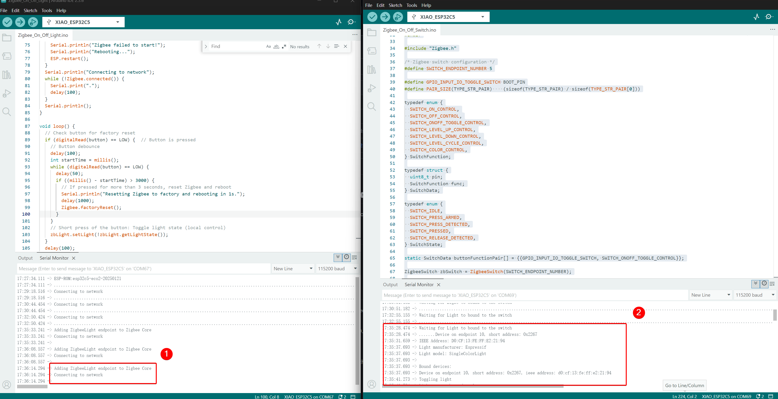
- 制御効果:BOOT ボタンが押されると、もう一方の XIAO ESP32-C5 の USER LED がトグルします。
技術サポートと製品ディスカッション
弊社製品をお選びいただき、ありがとうございます!弊社製品での体験が可能な限りスムーズになるよう、さまざまなサポートを提供しています。異なる好みやニーズに対応するため、複数のコミュニケーションチャンネルを提供しています。