XIAO nRF54LM20A Sense の低消費電力モード
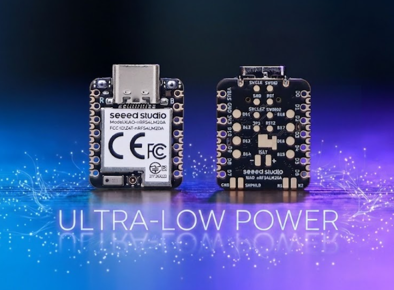
XIAO nRF54LM20A は nRF54LM20 SoC をベースとしており、超低消費電力を特長とします。その優れた低消費電力性能により、ウェアラブル機器、IoT エンドノード、リモートセンシングユニットなど、バッテリーが重要となるアプリケーションでの動作時間を効果的に延長できます。本ドキュメントでは、XIAO nRF54LM20A 上でさまざまな低消費電力モードを実装・展開する方法について説明します。
このチュートリアルは PlatformIO ビルドシステムと Zephyr RTOS をベースに作成されています。PlatformIO 上で XIAO nRF54LM20A 用プロジェクトの作成に不慣れな場合は、Getting Sarted With Seeed Studio XIAO nRF54LM20A にジャンプしてください。
ハードウェアの準備
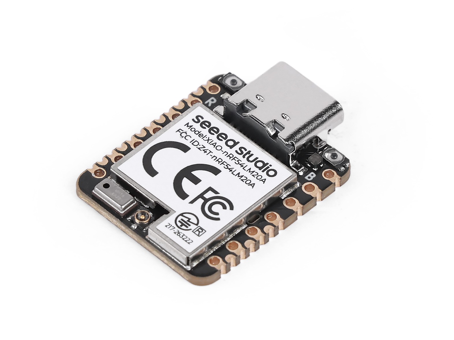
| SeeedStudio XIAO nRF54LM20A Sense |
|---|
 |
バッテリー駆動
本章で実装するすべてのモードは、USB-C からの給電ではなく、XIAO nRF54LM20A のボトムパッド経由でのバッテリー電源供給を採用しています。 XIAO nRF54LM20A は、電源入力として 3.7V リチウムバッテリーを使用できます。配線方法については、次の図を参照してください。
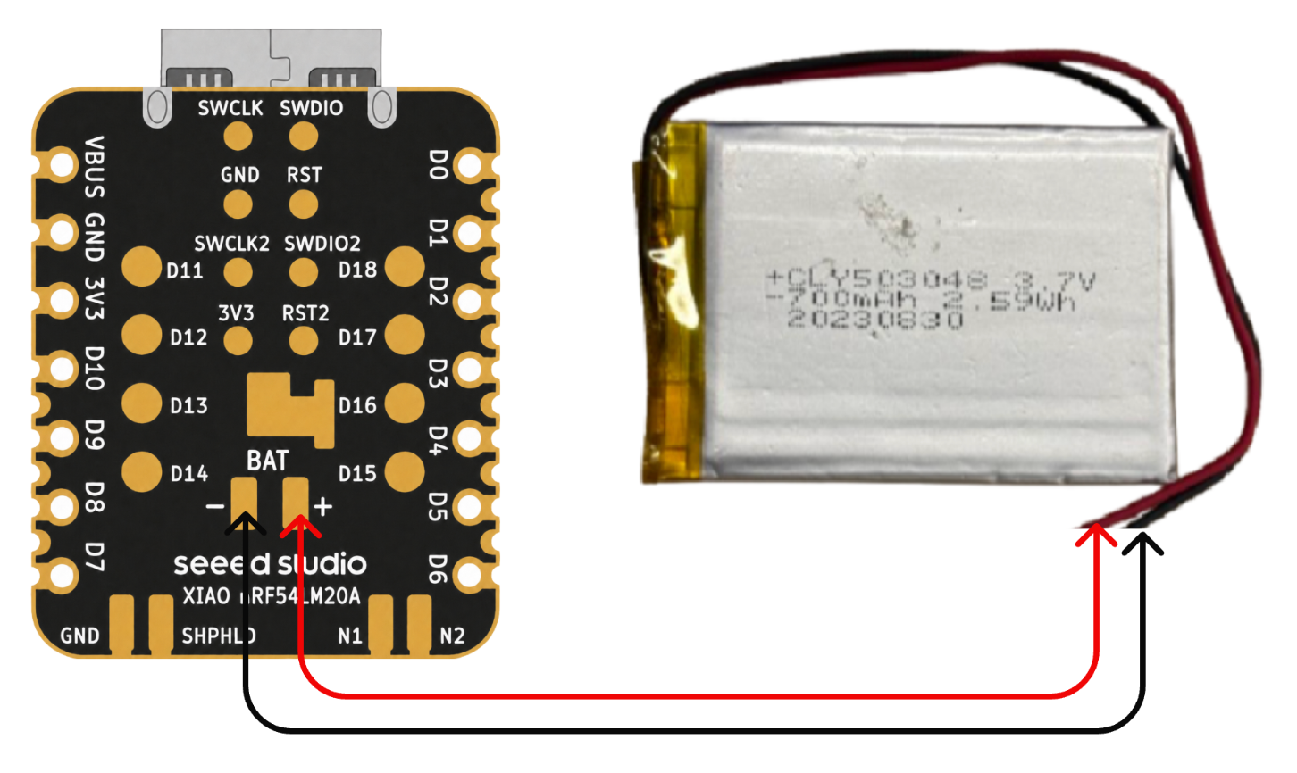
はんだ付けの際は、バッテリーや機器を損傷させる原因となるため、正極と負極をショートさせないよう十分注意してください。 バッテリーに電力が残っている状態で、決して基板にはんだ付けしないでください。基板が焼損するおそれがあります。通電中にショートさせることは重大なリスクを伴うため、アダプタの使用を推奨します。
低消費電力モード
低消費電力モードは、XIAO nRF54LM20A 上で System ON Sleep などの機能を用いて実装されます。このモードでは、システムを動作状態に保ったまま消費電力を削減します。CPU クロックはゲートされ一時停止しますが、RAM の内容、ペリフェラルの状態、プログラムコンテキストは完全に保持され、GRTC を含む低消費電力タイマは動作し続けます。本セクションでは、k_sleep 関数と BLE アドバタイジングを用いて低消費電力モードを検証します。
ソフトウェア
.overlayで終わるデバイスツリーファイルを修正します。
/ {
    chosen {
        zephyr,bt-hci = &bt_hci_controller;
    };
};

&bt_hci_controller {
    status = "okay";
};

/* Disable unused regulators to reduce standby power */
&power_en {
    /delete-property/ regulator-boot-on;
};

&pmic {
    regulators {
        LDO1 {
            /delete-property/ regulator-boot-on;
        };
    };
};
prj.conf設定ファイルを修正し、システム電源管理設定を有効にします。
CONFIG_GPIO=y
CONFIG_ARM_MPU=n
CONFIG_NRFX_POWER=y
CONFIG_POWEROFF=y
CONFIG_HWINFO=y
CONFIG_CRC=y

# Device power management (peripheral level)
CONFIG_PM_DEVICE=y
CONFIG_PM_DEVICE_RUNTIME=y

# Bluetooth
CONFIG_BT=y
CONFIG_BT_BROADCASTER=y
CONFIG_BT_DEVICE_NAME="XIAO nRF54LM20A"
CONFIG_BT_CTLR_ASSERT_OPTIMIZE_FOR_SIZE=n
CONFIG_BT_CTLR_ASSERT_DEBUG=n
CONFIG_BT_CTLR_ASSERT_OVERHEAD_START=n
- main.c プログラムを修正し、
k_sleep(K_SECONDS(10))で低消費電力モードを有効にするとともに、BLE が 1 秒間隔で定期的にメッセージをブロードキャストするよう設定します。
/*
* BLE Low Power Broadcasting Demo for XIAO nRF54LM20A
*/
#include <zephyr/kernel.h>
#include <zephyr/bluetooth/bluetooth.h>
#include <zephyr/bluetooth/hci.h>
/* 1000ms / 0.625ms = 1600 = 0x0640 */
#define ADV_INTERVAL_1S 0x0640
static const struct bt_data ad[] = {
BT_DATA_BYTES(BT_DATA_FLAGS, (BT_LE_AD_GENERAL | BT_LE_AD_NO_BREDR)),
BT_DATA(BT_DATA_NAME_COMPLETE, "XIAO nRF54LM20A", 15),
};
static void bt_ready(int err)
{
if (err) {
return;
}
struct bt_le_adv_param param = BT_LE_ADV_PARAM_INIT(
BT_LE_ADV_OPT_NONE,
ADV_INTERVAL_1S,
ADV_INTERVAL_1S,
NULL
);
bt_le_adv_start(¶m, ad, ARRAY_SIZE(ad), NULL, 0);
}
int main(void)
{
bt_enable(bt_ready);
/* BLE controller handles advertising autonomously; CPU sleeps */
while (1) {
k_sleep(K_SECONDS(10));
}
return 0;
}
結果
ファームウェアを書き込んだ後、電力消費テスターを使用して、低消費電力状態における XIAO nRF54LM20A の動作電流を測定できます。
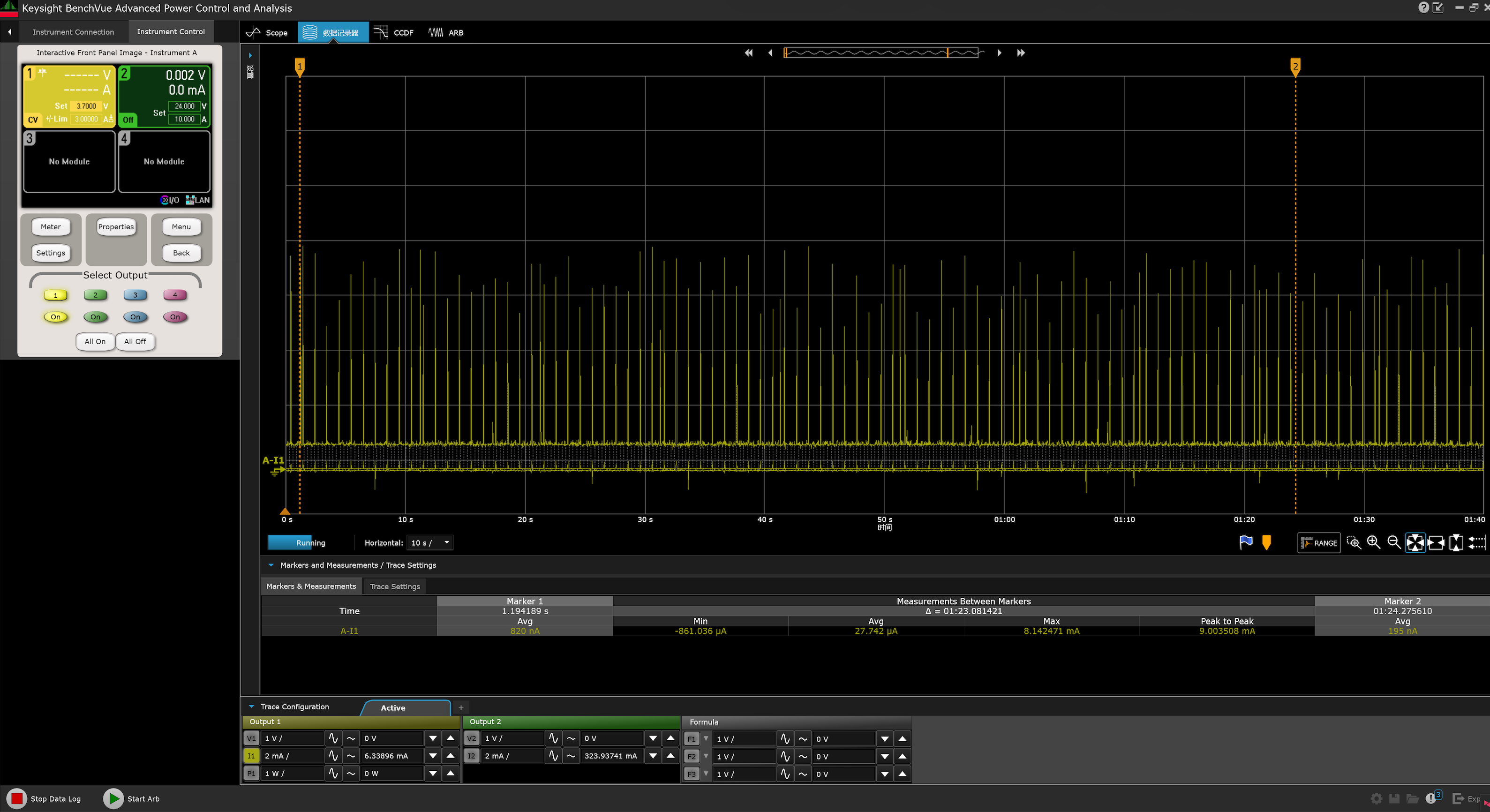
同時に、Bluetooth でスキャンすると、XIAO nRF54LM20A という名前でアドバタイズしているデバイスを見つけることができます。
- Android: nRF Connect
- IOS: nRF Connect
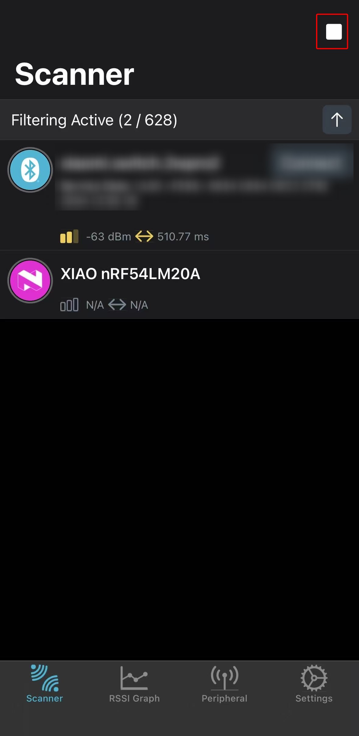 | 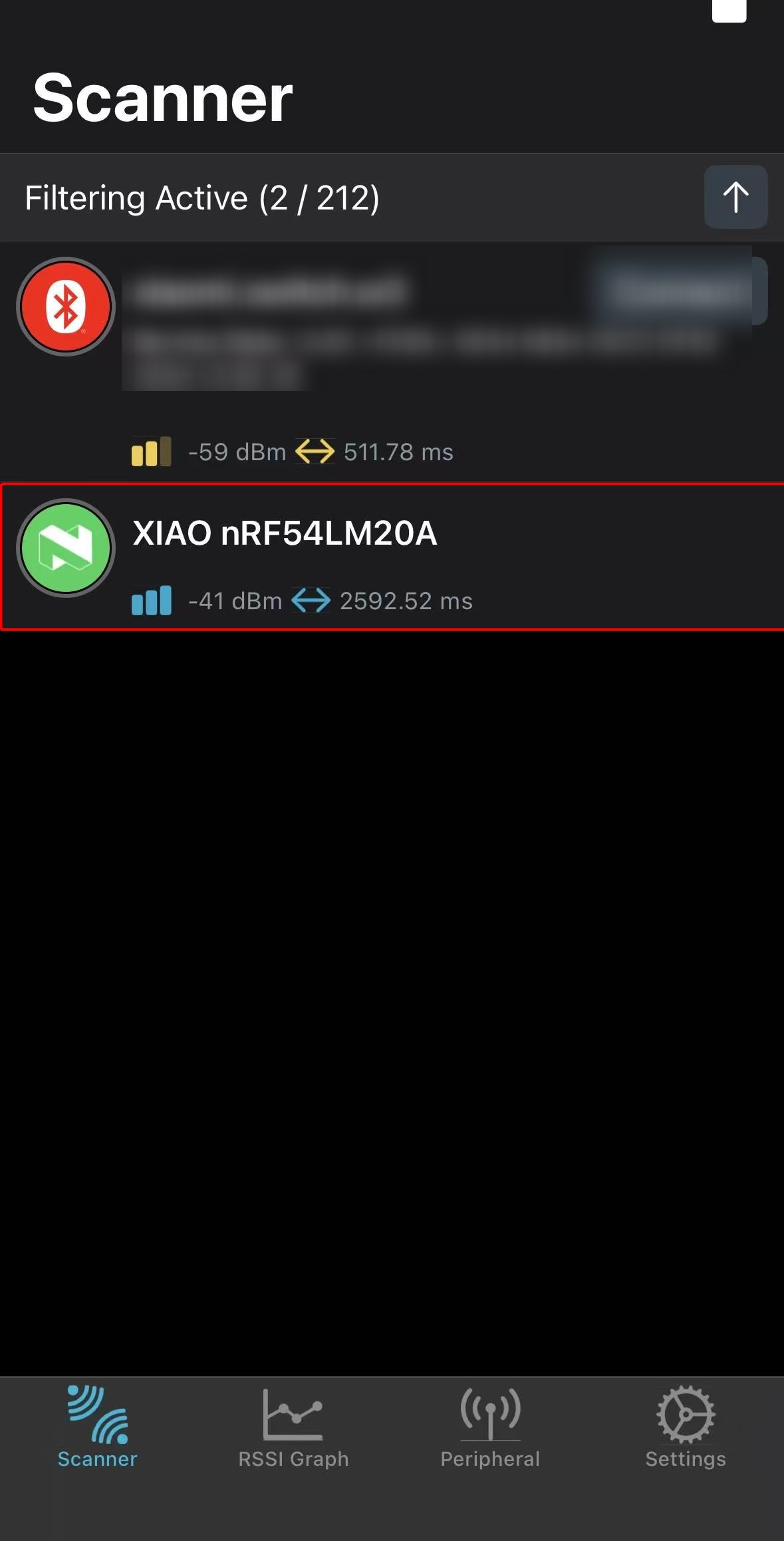 |
上記のテスト結果は、実験室環境下で測定されたものです。値は環境や測定機器の違いにより変動する場合があります。実際の測定結果を参照してください。
超低消費電力モード
XIAO nRF54LM20A は System OFF によって超低消費電力モードを実現します。このモードに入ると、すべてのペリフェラルクロックが停止し、ほとんどのペリフェラルの電源が完全にオフになるため、待機電流は最小で 5 µA まで低減されます。ウェイクアップトリガには、GRTC タイマまたは GPIO 割り込みが含まれます。システム状態は保持されず、ウェイクアップ後は電源再投入時と同様に動作し、プログラムは main() 関数から再スタートします。
本セクションでは、GPIO 割り込みによるウェイクアップを用いて、XIAO nRF54LM20A 上での System OFF モードの実動作性能を検証します。
ソフトウェア
この例では、外部フラッシュを手動でディープパワーダウンモードに移行させ、その SPI ピンを定義済みの状態に駆動する必要があります。そうしないと、追加のリーク電流が発生する可能性があります。
.overlayサフィックス付きのデバイスツリーファイルを修正します。
&power_en {
	/delete-property/ regulator-boot-on;
};

&pmic {
	regulators {
		LDO1 {
			/delete-property/ regulator-boot-on;
		};
	};
};

&pmic_leds {
	status = "disabled";
};

&py25q64 {
	status = "okay";
};
prj.confファイルを修正し、電源管理を含む各種設定を有効にします。
CONFIG_SERIAL=y
CONFIG_CONSOLE=y
CONFIG_UART_CONSOLE=y
CONFIG_PRINTK=y
CONFIG_BOOT_BANNER=n

CONFIG_GPIO=y
CONFIG_SPI=y
CONFIG_FLASH=y
CONFIG_SPI_NOR=y

CONFIG_PM_DEVICE=y
CONFIG_PM_DEVICE_RUNTIME=y
CONFIG_POWEROFF=y
CONFIG_HWINFO=y

CONFIG_BT=n
- main.c プログラムを作成し、オンボードの Boot ボタンが押されたときに、超低消費電力モードからチップをウェイクアップさせます。
main.c
/*
 * Copyright (c) 2019 Nordic Semiconductor ASA
 *
 * SPDX-License-Identifier: Apache-2.0
 */
/*
 * Ultra-low-power System OFF demo for XIAO nRF54LM20A Sense.
 *
 * Confirmed board resources from the board DTS:
 * - sw0 / BOOT: P0.09 (active low with pull-up)
 * - External flash (PY25Q64HA) on spi00:
 *   HOLD# P2.00, SCK P2.01, MOSI P2.02, WP# P2.03, MISO P2.04, CS# P2.05
 * - RGB LEDs on P1.22 / P1.23 / P1.24
 */
#include <errno.h>
#include <inttypes.h>
#include <stdio.h>

#include <zephyr/device.h>
#include <zephyr/drivers/gpio.h>
#include <zephyr/drivers/hwinfo.h>
#include <zephyr/kernel.h>
#include <zephyr/pm/device.h>
#include <zephyr/sys/poweroff.h>

static const struct gpio_dt_spec sw0 = GPIO_DT_SPEC_GET(DT_ALIAS(sw0), gpios);
static const struct gpio_dt_spec led_red = GPIO_DT_SPEC_GET(DT_ALIAS(led1), gpios);
static const struct gpio_dt_spec led_blue = GPIO_DT_SPEC_GET(DT_ALIAS(led0), gpios);
static const struct gpio_dt_spec led_green = GPIO_DT_SPEC_GET(DT_ALIAS(led2), gpios);

#if DT_NODE_EXISTS(DT_CHOSEN(zephyr_console))
static const struct device *const cons = DEVICE_DT_GET(DT_CHOSEN(zephyr_console));
#endif

#if DT_NODE_HAS_STATUS(DT_NODELABEL(py25q64), okay)
static const struct device *const flash_dev = DEVICE_DT_GET(DT_NODELABEL(py25q64));
static const struct device *const flash_bus = DEVICE_DT_GET(DT_BUS(DT_NODELABEL(py25q64)));
#endif

static void print_reset_cause(uint32_t reset_cause)
{
	if (reset_cause & RESET_DEBUG) {
		printf("Reset by debugger.\n");
	} else if (reset_cause & RESET_CLOCK) {
		printf("Wakeup from System OFF by clock source.\n");
	} else if (reset_cause & RESET_LOW_POWER_WAKE) {
		printf("Wakeup from System OFF by GPIO.\n");
	} else if (reset_cause != 0U) {
		printf("Other wake up cause 0x%08" PRIX32 ".\n", reset_cause);
	} else {
		printf("Power-on reset or reset cause unavailable.\n");
	}
}

static int configure_gpio_wakeup(void)
{
	int rc;

	if (!gpio_is_ready_dt(&sw0)) {
		printf("sw0 GPIO device not ready.\n");
		return -ENODEV;
	}

	rc = gpio_pin_configure_dt(&sw0, GPIO_INPUT);
	if (rc < 0) {
		printf("Could not configure sw0 GPIO (%d)\n", rc);
		return rc;
	}

	rc = gpio_pin_interrupt_configure_dt(&sw0, GPIO_INT_LEVEL_ACTIVE);
	if (rc < 0) {
		printf("Could not configure sw0 GPIO interrupt (%d)\n", rc);
		return rc;
	}

	return 0;
}

static void release_led(const struct gpio_dt_spec *led, const char *name)
{
	int rc;

	if (!gpio_is_ready_dt(led)) {
		return;
	}

	rc = gpio_pin_configure(led->port, led->pin, GPIO_DISCONNECTED);
	if (rc < 0) {
		printf("Warning: could not disconnect %s (%d)\n", name, rc);
	}
}

static void release_led_gpios(void)
{
	release_led(&led_red, "red LED");
	release_led(&led_blue, "blue LED");
	release_led(&led_green, "green LED");
}

/*
 * Put the external flash pins into deterministic, low-leakage states before
 * System OFF. These pin numbers are confirmed by the board pinctrl and DTS.
 */
static int configure_spi_pins_for_system_off(void)
{
	const struct device *gpio2 = DEVICE_DT_GET(DT_NODELABEL(gpio2));
	int rc;

	if (!device_is_ready(gpio2)) {
		printf("GPIO2 not ready.\n");
		return -ENODEV;
	}

	rc = gpio_pin_configure(gpio2, 5, GPIO_OUTPUT_HIGH);
	if (rc < 0) {
		return rc;
	}

	rc = gpio_pin_configure(gpio2, 0, GPIO_OUTPUT_HIGH);
	if (rc < 0) {
		return rc;
	}

	rc = gpio_pin_configure(gpio2, 3, GPIO_OUTPUT_HIGH);
	if (rc < 0) {
		return rc;
	}

	rc = gpio_pin_configure(gpio2, 1, GPIO_OUTPUT_LOW);
	if (rc < 0) {
		return rc;
	}

	rc = gpio_pin_configure(gpio2, 2, GPIO_OUTPUT_LOW);
	if (rc < 0) {
		return rc;
	}

	rc = gpio_pin_configure(gpio2, 4, GPIO_INPUT | GPIO_PULL_DOWN);
	if (rc < 0) {
		return rc;
	}

	return 0;
}

static int suspend_external_flash(void)
{
	int first_error = 0;
	int rc;

#if DT_NODE_HAS_STATUS(DT_NODELABEL(py25q64), okay)
	if (device_is_ready(flash_dev)) {
		rc = pm_device_action_run(flash_dev, PM_DEVICE_ACTION_SUSPEND);
		if ((rc < 0) && (first_error == 0)) {
			first_error = rc;
			printf("Warning: could not suspend external flash (%d)\n", rc);
		}
	} else {
		first_error = -ENODEV;
		printf("Warning: flash device is not ready; skipping driver DPD.\n");
	}

	if (device_is_ready(flash_bus)) {
		rc = pm_device_action_run(flash_bus, PM_DEVICE_ACTION_SUSPEND);
		if ((rc < 0) && (first_error == 0)) {
			first_error = rc;
			printf("Warning: could not suspend SPI bus (%d)\n", rc);
		}
	} else if (first_error == 0) {
		first_error = -ENODEV;
		printf("Warning: flash SPI bus is not ready.\n");
	}
#else
	first_error = -ENODEV;
	printf("Warning: py25q64 is not enabled in DTS.\n");
#endif

	rc = configure_spi_pins_for_system_off();
	if ((rc < 0) && (first_error == 0)) {
		first_error = rc;
		printf("Warning: could not configure flash SPI pins (%d)\n", rc);
	}

	return first_error;
}

static void suspend_console_best_effort(void)
{
#if DT_NODE_EXISTS(DT_CHOSEN(zephyr_console))
	int rc;

	if (!device_is_ready(cons)) {
		return;
	}

	rc = pm_device_action_run(cons, PM_DEVICE_ACTION_SUSPEND);
	if (rc < 0) {
		printf("Warning: could not suspend console (%d)\n", rc);
	}
#endif
}

int main(void)
{
	int rc;
	uint32_t reset_cause = 0U;

	printf("\n=== %s ultra-low-power system off demo ===\n", CONFIG_BOARD);

	rc = hwinfo_get_reset_cause(&reset_cause);
	if (rc == 0) {
		print_reset_cause(reset_cause);
	} else {
		printf("Warning: could not read reset cause (%d)\n", rc);
	}

	rc = configure_gpio_wakeup();
	if (rc < 0) {
		printf("Error: wakeup source configuration failed, aborting System OFF.\n");
		return 0;
	}

	release_led_gpios();

	rc = suspend_external_flash();
	if (rc < 0) {
		printf("Warning: flash low-power preparation incomplete (%d)\n", rc);
	}

	printf("Entering system off; press BOOT/SW0 to restart.\n");
	k_msleep(20);

	suspend_console_best_effort();

	rc = hwinfo_clear_reset_cause();
	if (rc < 0) {
		/* Clear failure should not stop entry into System OFF. */
		printf("Warning: could not clear reset cause (%d)\n", rc);
	}

	sys_poweroff();

	while (1) {
		k_sleep(K_FOREVER);
	}
}
結果
起動後、ファームウェアはウェイクアップソースと外部ペリフェラルを準備し、その後自動的に System OFF に入ります。XIAO nRF54LM20A を消費電力テスターで測定したところ、3.7 V バッテリーで駆動した場合の平均動作電流は約 3.74 µA でした。
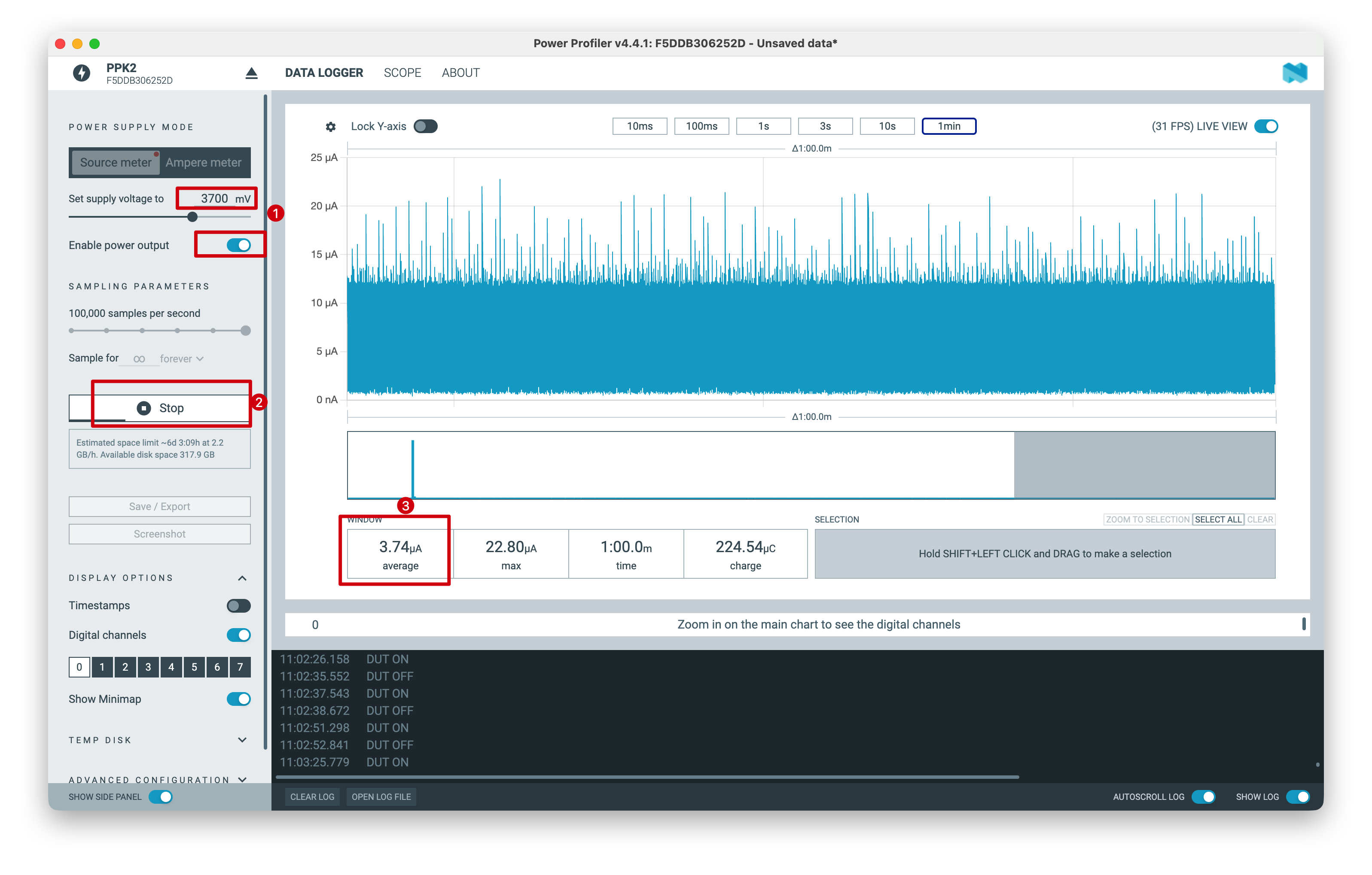
上記のテスト結果は、実験室環境下で測定されたものです。値は環境やテスト機器の違いにより変動する場合があります。実際の測定性能を参照してください。
技術サポートと製品ディスカッション
弊社製品をお選びいただきありがとうございます。私たちは、製品をできるだけスムーズにご利用いただけるよう、さまざまなサポートを提供しています。お好みやニーズに応じてお選びいただける、複数のコミュニケーションチャネルをご用意しています。