Seeed Studio XIAO ESP32C6でのArduinoプログラミング
| Seeed Studio XIAO ESP32C6 |
|---|
 |
Seeed Studio XIAO ESP32C6は、高度に統合されたESP32-C6 SoCを搭載し、2つの32ビットRISC-Vプロセッサで構築されています。高性能(HP)プロセッサは最大160MHzで動作し、低消費電力(LP)32ビットRISC-Vプロセッサは最大20MHzでクロック動作可能です。チップには512KBのSRAMと4MBのFlashが搭載されており、より多くのプログラミング領域を提供し、IoT制御シナリオにより多くの可能性をもたらします。
はじめに
ピン配置の概要
始める前に、XIAO ESP32C6が持つすべてのピンとその機能を以下の回路図で確認しましょう。
| XIAO ESP32C6/XIAO ESP32C6 表示図 |
|---|
| XIAO ESP32C6/XIAO ESP32C6 Sense ピンリスト |
- 5V - これはUSBポートからの5v出力です。電圧入力としても使用できますが、外部電源とこのピンの間に何らかのダイオード(ショットキー、信号、電力)を配置する必要があります。アノードをバッテリーに、カソードを5Vピンに接続してください。
- 3V3 - これはオンボードレギュレータからの調整済み出力です。700mAまで引き出すことができます。
- GND - 電源/データ/信号グランド
シリアル通信
XIAO ESP32C6とのシリアル通信には2つの方法があります:ソフトウェアシリアルとハードウェアシリアルです。ソフトウェアシリアルは柔軟性のために一般的に使用され、ハードウェアシリアルはより良いパフォーマンスを提供します。
ハードウェアセットアップ
- 外部デバイスのTXピンをXIAO ESP32C6のRXピン(
D7)に接続します。 - 外部デバイスのRXピンをXIAO ESP32C6のTXピン(
D6)に接続します。
コード例
ソフトウェアシリアル
ソフトウェアシリアルを使用するには、EspSoftwareSerialライブラリをインストールしてください。
現在、EspSoftwareSerialライブラリのバージョン7.0.0を推奨しています。他のバージョンでは、ソフトシリアルポートが正常に動作しない様々な程度の問題が発生する可能性があります。
#include <SoftwareSerial.h>

SoftwareSerial mySerial(D7, D6); // RX, TX

void setup() {
  Serial.begin(9600);
  mySerial.begin(9600);
}

void loop() {
  if (mySerial.available()) {
    char data = mySerial.read();
    Serial.print("Received via software serial: ");
    Serial.println(data);
  }

  if (Serial.available()) {
    char data = Serial.read();
    mySerial.print("Received via hardware serial: ");
    mySerial.println(data);
  }
}
この例では、ピン D7 (RX) と D6 (TX) でソフトウェアシリアルを9600ボーで設定します。ハードウェアシリアル(USB)とソフトウェアシリアルポートの両方を監視し、受信したデータを相互にエコーします。
ハードウェアシリアル
XIAO ESP32C6 は、シリアル通信用のハードウェアUART(UART0)を搭載しており、ピンD7/D6に対応しています。
#include <HardwareSerial.h>

HardwareSerial mySerial(0); // UART0 (Serial0)

void setup() {
  Serial.begin(9600);  // USB serial
  mySerial.begin(9600); // UART0
}

void loop() {
  if (Serial.available()) {
    char data = Serial.read();
    Serial.print("Received on USB: ");
    Serial.println(data);
  }

  if (mySerial.available()) {
    char data = mySerial.read();
    Serial.print("Received on UART0: ");
    Serial.println(data);
  }
}
この例では、通信にハードウェアUART0(Serial0)を使用しています。USBシリアルとUART0の両方を初期化し、両方のポートで受信データを監視し、受信したメッセージをUSBシリアルポートに出力します。
Serial1の使用方法
上記のXIAO ESP32C6 ピン図の具体的なパラメータによると、TXピンとRXピンがあることが確認できます。 これはシリアル通信とは異なりますが、使用方法も非常に似ており、いくつかのパラメータを追加する必要があるだけです。 そこで次に、チップから引き出されたピンをシリアル通信に使用します。
含める必要があるコア関数:
Serial1.begin(BAUD,SERIAL_8N1,RX_PIN,TX_PIN);-- Serial1を有効化、関数プロトタイプ:<Serial.Type>.begin(unsigned long baud, uint32_t config, int8_t rxPin, int8_t txPin);baud:ボーレートconfig:設定ビットrxPin:受信ピンtxPin:送信ピン
注目すべき点は、デジタルピンポートを使用して定義する場合、ここは#define RX_PIN D7、#define TX_PIN D6とする必要があることです。具体的なパラメータについては、異なるXIAOシリーズのピン図を参照してください。
以下はサンプルプログラムです:
#define RX_PIN D7
#define TX_PIN D6
#define BAUD 115200

void setup() {
    Serial1.begin(BAUD,SERIAL_8N1,RX_PIN,TX_PIN);
}

void loop() {
  if(Serial1.available() > 0)
  {
    char incominByte = Serial1.read();
    Serial1.print("I received : ");
    Serial1.println(incominByte);
  }
  delay(1000);
}
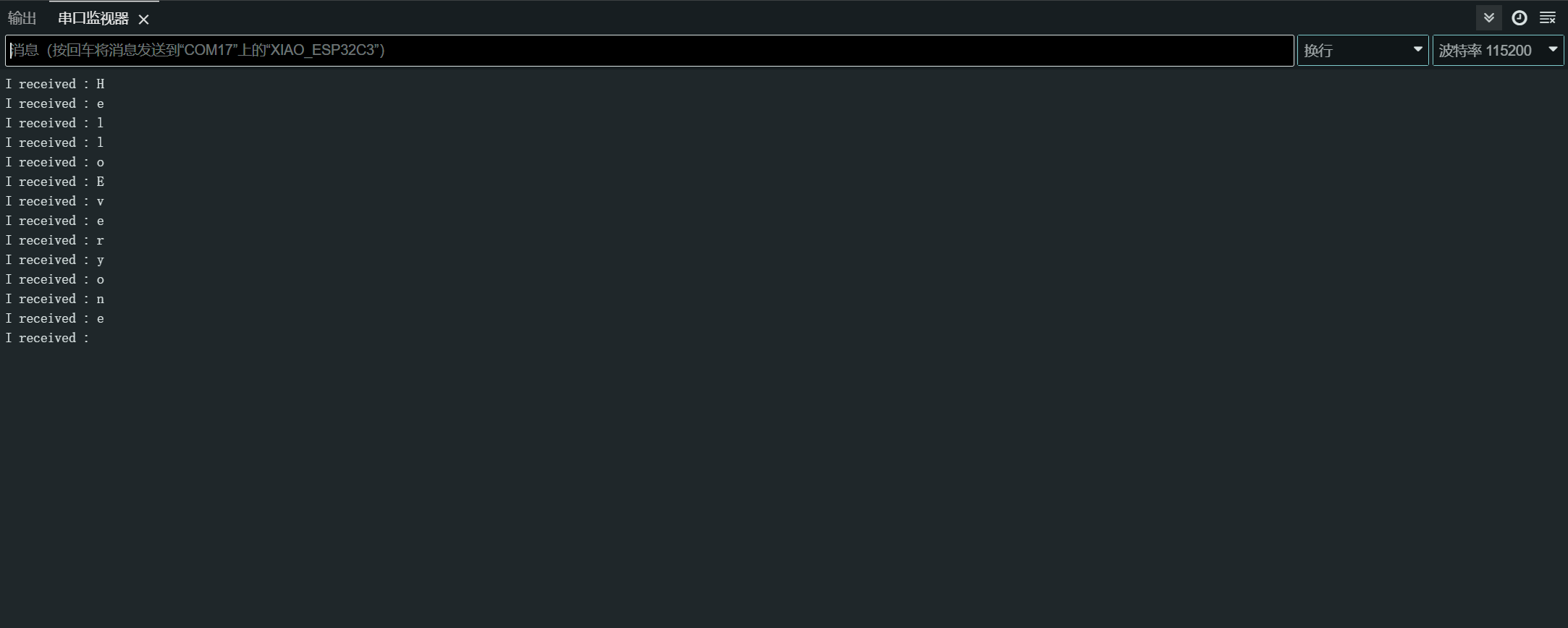
プログラムをアップロードした後、Arduino IDEでシリアルモニターを開き、ボーレートを115200に設定します。その後、シリアルモニターSerial経由でXIAO ESP32C6に送信したい内容を送ることができ、XIAOは送信した内容の各バイトを出力します。ここでは、入力した内容は「Hello Everyone」で、結果チャートは以下の通りです。
デジタル I/O
XIAO ESP32C6には、入力または出力として設定できる12個のGPIOピンがあります。
ハードウェア準備
- ピン
D1にボタンを接続します:- 外部プルアップ抵抗を使用します(内部プルアップ抵抗を使用する場合はオプション)。
- ピン
D10にLEDを接続します:- LEDと直列に電流制限抵抗を含めます。
ソフトウェア実装
GPIO APIは、GPIOピンを設定し、相互作用するための関数を提供します。詳細については、GPIO APIドキュメントを参照してください。
const int buttonPin = D1; // Button pin
const int ledPin = D10; // LED pin

void setup() {
  pinMode(ledPin, OUTPUT); // Set LED pin as output
  pinMode(buttonPin, INPUT); // Set button pin as input
  // If not using an external pull-up resistor
  pinMode(buttonPin, INPUT_PULLUP); // Enable internal pull-up resistor
}

void loop() {
  int buttonState = digitalRead(buttonPin); // Read button state
  digitalWrite(ledPin, buttonState); // Write button state to LED
}
割り込み方式
割り込みを使用してボタンの押下をより効率的に処理することもできます。
// Define the pin numbers for the button and LED
const int buttonPin = D1;
const int ledPin = D10;

// Define a structure to hold button-related data
struct Button {
    const uint8_t PIN; // Pin number for the button
    uint32_t numberKeyPresses; // Counter for the number of button presses
    bool pressed; // Flag to indicate if the button is currently pressed
};

// Create an instance of the Button structure for the button
Button my_button = {buttonPin, 0, false};

// Interrupt Service Routine (ISR) to handle button presses
void ARDUINO_ISR_ATTR isr(void* arg) {
    Button* s = static_cast<Button*>(arg); // Cast the argument to a Button pointer
    s->numberKeyPresses += 1; // Increment the number of button presses
    s->pressed = true; // Set the pressed flag
}

void setup() {
    Serial.begin(115200);
    pinMode(my_button.PIN, INPUT_PULLUP); // Set the button pin as input with internal pull-up resistor
    attachInterruptArg(my_button.PIN, isr, &my_button, FALLING); // Attach the ISR to the button pin, triggered on falling edge
}

void loop() {
    if (my_button.pressed) { // Check if the button is pressed
        Serial.printf("Button 1 has been pressed %lu times\n", my_button.numberKeyPresses); // Print the number of button presses
        my_button.pressed = false; // Reset the pressed flag
    }

    static uint32_t lastMillis = 0; // Variable to store the last time the interrupt was detached
    if (millis() - lastMillis > 10000) { // Check if 10 seconds have elapsed
        lastMillis = millis(); // Update the last detach time
        detachInterrupt(my_button.PIN); // Detach the interrupt from the button pin
    }
}
この例では、ボタン関連のデータを保持するために Button 構造体を使用しています。これには、ピン番号、キー押下回数、およびボタンが現在押されているかどうかを示すフラグが含まれています。
isr 関数は、ボタン押下を処理する割り込みサービスルーチン(ISR)です。この関数は、ボタン押下回数をインクリメントし、押下フラグを true に設定します。
setup 関数では、シリアル通信を初期化し、ボタンピンを内部プルアップ抵抗付きの入力として設定し、isr 関数をボタンピンに割り込みハンドラとして接続します。これは立ち下がりエッジ(ボタン押下)でトリガーされます。
loop 関数では、ボタンが押されているかどうかをチェックします。押されている場合は、ボタン押下回数をシリアルモニターに出力し、押下フラグをリセットします。さらに、10秒ごとにボタンピンから割り込みを切り離すセクションも含まれており、これは他の操作を可能にするため、または意図しない割り込みを防ぐためと思われます。
了解しました。以下が書き直されたより理解しやすいバージョンです:
ADC - アナログデジタル変換器
XIAO ESP32C6 には、アナログ電圧を読み取ることができる複数のアナログ入力ピンがあります。
詳細については、ADC API ドキュメントを参照してください。
ハードウェアセットアップ
- ポテンショメータをピン A0 に接続し、一端を 3.3V に、もう一端を GND に接続します。
ソフトウェア実装
以下は、アナログ値を読み取る Arduino スケッチです:
const int analogPin = A0;

void setup() {
  // Initialize serial communication at 115200 bits per second
  Serial.begin(115200);

  // Set the resolution to 12 bits (0-4095)
  analogReadResolution(12);
}

void loop() {
  // Read the analog value and millivolts for the analogPin
  int analogValue = analogRead(analogPin);
  int analogVolts = analogReadMilliVolts(analogPin);

  // Print the values to the Serial Monitor
  Serial.printf("ADC analog value = %d\n", analogValue);
  Serial.printf("ADC millivolts value = %d\n", analogVolts);

  delay(100); // Delay for clear reading from serial
}
このコードは、指定されたピンからアナログ値を読み取り、ミリボルト値と共にシリアルモニターに出力します。
PWM信号 / LED制御
XIAO ESP32-C6には6つのLEDCチャンネルがあり、独立した波形を生成できます。これは例えばRGB LEDデバイスの駆動に使用できます。
詳細についてはLEDC APIドキュメントを参照してください。
ハードウェアセットアップ
- 電流制限抵抗を直列に接続してLEDをピン
D2に接続します。
ソフトウェア実装
PWM出力を実演するArduinoスケッチは以下の通りです:
一般的なPWM
const int ledPin = D2;

void setup() {
  pinMode(ledPin, OUTPUT);
}

void loop() {
  for (int dutyCycle = 0; dutyCycle <= 255; dutyCycle++) {
    analogWrite(ledPin, dutyCycle);
    delay(10);
  }
}
このコードはPWMを使用してLEDの明るさを徐々に増加させます。
LED制御
/*
 LEDC Software Fade

 This example shows how to software fade an LED
 using the ledcWrite function.

 Code adapted from the original Arduino Fade example:
 https://www.arduino.cc/en/Tutorial/Fade

 This example code is in the public domain.
 */

// Use 12-bit precision for the LEDC timer
#define LEDC_TIMER_12_BIT  12

// Use 5000 Hz as the LEDC base frequency
#define LEDC_BASE_FREQ     5000

// Fade LED PIN (replace with LED_BUILTIN constant for the built-in LED)
#define LED_PIN            D5

int brightness = 0;    // How bright the LED is
int fadeAmount = 5;    // How many points to fade the LED by

// Arduino-like analogWrite
// Value has to be between 0 and valueMax
void ledcAnalogWrite(uint8_t pin, uint32_t value, uint32_t valueMax = 255) {
  // Calculate duty, 4095 from 2 ^ 12 - 1
  uint32_t duty = (4095 / valueMax) * min(value, valueMax);

  // Write duty to LEDC
  ledcWrite(pin, duty);
}

void setup() {
  // Setup timer and attach timer to the LED pin
  ledcAttach(LED_PIN, LEDC_BASE_FREQ, LEDC_TIMER_12_BIT);
}

void loop() {
  // Set the brightness on the LEDC channel
  ledcAnalogWrite(LED_PIN, brightness);

  // Change the brightness for the next loop iteration
  brightness = brightness + fadeAmount;

  // Reverse the direction of the fading at the ends of the fade
  if (brightness <= 0 || brightness >= 255) {
    fadeAmount = -fadeAmount;
  }
  // Wait for 30 milliseconds to see the dimming effect
  delay(30);
}
このコードは、ledcWrite関数を使用してLEDをフェードする方法を示しています。LEDの明るさは連続ループで徐々に増加および減少します。
I2C
XIAO ESP32C6は、I2Cデバイスと通信するためのハードウェアI2Cインターフェースを備えています。
詳細については、I2C APIドキュメントを参照してください。
ハードウェア準備
- I2CデバイスのSDAピンをXIAOのSDAピン(
D4)に接続します。 - I2CデバイスのSCLピンをXIAOのSCLピン(
D5)に接続します。
ソフトウェア実装
マスターモード
以下は、I2Cセンサーからの読み取りを実演するArduinoスケッチです:
#include <Wire.h>

const int sensorAddress = 0x40;

void setup() {
  Wire.begin();
  Serial.begin(115200);
}

void loop() {
  Wire.beginTransmission(sensorAddress);
  Wire.write(0x01);  // Register address
  Wire.endTransmission();

  Wire.requestFrom(sensorAddress, 2);
  if (Wire.available() >= 2) {
    int data = Wire.read() << 8 | Wire.read();
    Serial.println(data);
  }

  delay(100);
}
このコードは、I2Cセンサーのレジスタ0x01から16ビット値を読み取ります。
スレーブモード
以下は、XIAO ESP32C6をI2Cスレーブデバイスとして使用することを実演するArduinoスケッチです:
#include "Wire.h"

#define I2C_DEV_ADDR 0x55

uint32_t i = 0;

void onRequest() {
  Wire.print(i++);
  Wire.print(" Packets.");
  Serial.println("onRequest");
}

void onReceive(int len) {
  Serial.printf("onReceive[%d]: ", len);
  while (Wire.available()) {
    Serial.write(Wire.read());
  }
  Serial.println();
}

void setup() {
  Serial.begin(115200);
  Serial.setDebugOutput(true);
  Wire.onReceive(onReceive);
  Wire.onRequest(onRequest);
  Wire.begin((uint8_t)I2C_DEV_ADDR);

#if CONFIG_IDF_TARGET_ESP32
  char message[64];
  snprintf(message, 64, "%lu Packets.", i++);
  Wire.slaveWrite((uint8_t *)message, strlen(message));
#endif
}

void loop() {
  // Slave device code here
}
このスレーブモードの例では、XIAO ESP32C6 は I2C スレーブデバイスとしてアドレス 0x55 で設定されています。onReceive コールバック関数は、スレーブがマスターからデータを受信したときに呼び出され、onRequest コールバック関数は、マスターがスレーブからデータを要求したときに呼び出されます。
SPI
XIAO ESP32C6 マイクロコントローラーボードには内蔵の SPI インターフェースが搭載されており、他の SPI 対応デバイスとの高速データ交換を可能にします。これは、複数のデバイス間での迅速な通信が必要なプロジェクトで特に有用です。
- 詳細な技術仕様については、XIAO ESP32C6 データシートを参照してください。
- XIAO ESP32C6 で SPI インターフェースを使用する方法の詳細については、SPI API ドキュメントを参照してください。
ハードウェアの準備
XIAO ESP32C6 を他の SPI デバイスに接続するには、以下の手順に従ってください:
- MOSI (Master Out Slave In): SPI デバイスの
MOSIピンを XIAO のピンD10に接続します。 - MISO (Master In Slave Out): SPI デバイスの
MISOピンを XIAO のピンD9に接続します。 - SCK (Serial Clock): SPI デバイスの
SCKピンを XIAO のピンD8に接続します。 - CS (Chip Select): SPI デバイスの
CSピンを XIAO のデジタルピン(例:D3)に接続します。
MOSI -> D10
MISO -> D9
SCK -> D8
CS -> D3 (as an example)
ソフトウェア実装
以下は、XIAO ESP32C6を使用してSPIデバイスとの基本的なSPI通信を実演する簡略化されたArduinoスケッチです。このスケッチはSPIデバイスにコマンドを送信し、応答を読み返します(SPIデバイスからデータを読み返します)。
#include <SPI.h>

const int csPin = 3;  // Use pin D3 for Chip Select (CS)

void setup() {
  // Initialize SPI communication
  SPI.begin();
  // Set the CS pin as an output
  pinMode(csPin, OUTPUT);
  // Set the CS pin high to indicate no active communication
  digitalWrite(csPin, HIGH);
}

void loop() {
  // Start communication with the device
  digitalWrite(csPin, LOW);
  SPI.transfer(0x01);  // Send a command to the device
  int data = SPI.transfer(0);  // Read the response
  digitalWrite(csPin, HIGH);  // End communication

  // Print the received data
  Serial.println(data);
  delay(100);  // Wait for a short period
}
スケッチ内のピン割り当てが、ハードウェアセットアップの物理的な接続と一致していることを確認してください。上記の例では、XIAO ESP32-C6用のpin_arduino.hファイルに基づく事前定義されたピン番号を使用し、CSピン用の追加定義を含んでいます。