Jetson Camera
Architecture analysis and real-device experiments based on reComputer Classic J3010 + Sony IMX219
Introduction
The camera is one of the most common peripherals on the Jetson platform. From robot vision and industrial inspection to autonomous driving and embodied intelligence, the camera is an important entry point for the system to perceive the real world. However, during Jetson development, we often encounter some seemingly contradictory problems:
- The camera has been recognized by the system — why still can't it capture images?
/dev/video0already exists — why does runningv4l2-ctlstill report a Timeout?- What do NVCSI, VI, and ISP each do?
- How does the Sensor's RAW10 data become a viewable color image?
To understand these problems, it is not enough to just know V4L2 or GStreamer. We need to start from the hardware and understand which modules a single image frame passes through inside the Jetson, and how these modules work together. This article will introduce the following data chain:
Sensor → MIPI CSI-2 → NVCSI → VI → ISP → Application
At the same time, we will use a reComputer Classic J3010 actually running JetPack 6.2.1, together with a Sony IMX219 CSI Camera, to verify this data chain step by step. After reading this article, you will learn the following. I hope it helps you:
- The hardware architecture and complete data flow of the Jetson Camera.
- The specific responsibilities of the Sensor, NVCSI, VI, and ISP.
- The difference between the two acquisition paths: V4L2 RAW and Argus ISP.
- How to use Linux tools to observe the real Camera topology.
- How to capture RAW images and ISP-processed color images.
- How to locate camera problems using information such as VI Timeout and RTCPU Trace.
1. Real-Device Test Platform
The test device used in this article is the Seeed Studio reComputer Classic J3010, with a Sony IMX219 camera. The IMX219 is a common 8MP CMOS Image Sensor, also used in the Raspberry Pi Camera Module v2.
| Item | Configuration |
|---|---|
| Device | reComputer Classic J3010 |
| SoC | NVIDIA Jetson Orin Nano |
| JetPack | 6.2.1 |
| Jetson Linux | R36.4.3 |
| Ubuntu | 22.04.5 LTS |
| Linux Kernel | 5.15.148-tegra |
| Camera Sensor | Sony IMX219 |
| Camera Interface | MIPI CSI-2 |
| Maximum Sensor Resolution | 3280 × 2464 |
| Camera Data Format | RAW Bayer |
| Camera Driver | imx219 |
Note that the sensor specifications of the IMX219 may not exactly match the modes actually exposed by the current driver. The later experiments are based on the device enumeration results.
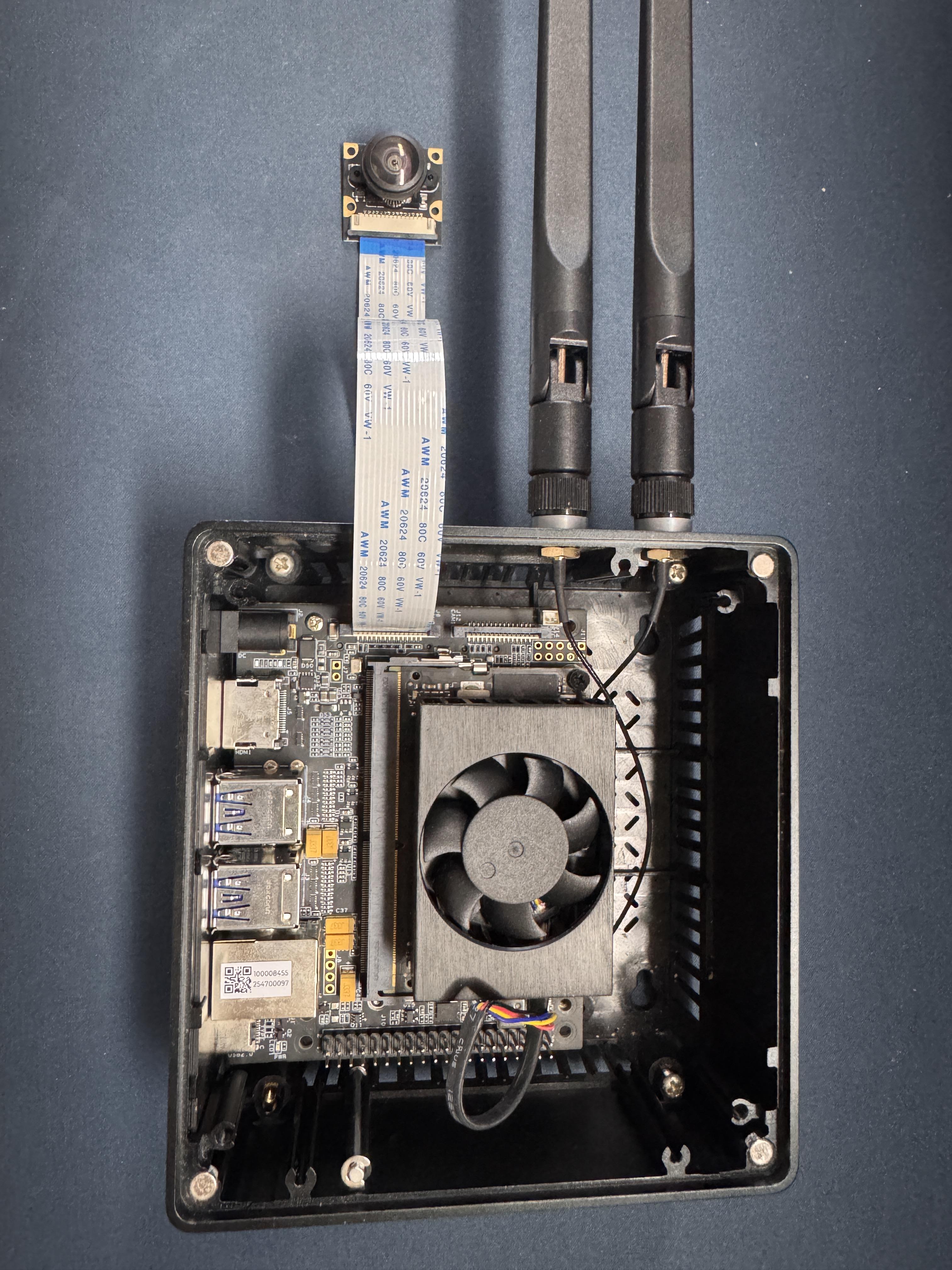
The experimental files in the rest of this article are uniformly saved to the ~/jetson-camera-test directory on the Jetson.
2. Overall Architecture of the Jetson Camera
First, we need to build a basic understanding: after image data enters the Jetson, it is not directly handed over to the CPU for processing.
For a typical MIPI CSI Bayer camera, the data needs to pass through multiple hardware modules.
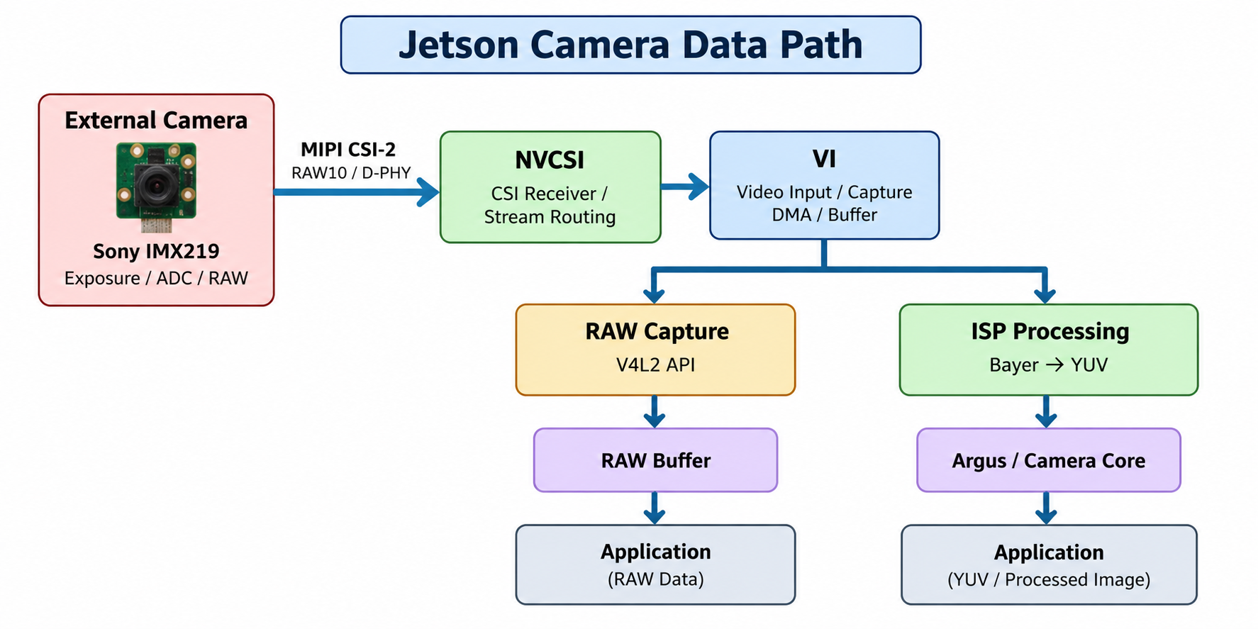
Note that the diagram above shows the logical relationship; it does not mean the ISP is necessarily physically connected after the VI DMA output. The actual data transfer and memory access are managed by the SoC's internal hardware and the NVIDIA Camera Framework.
What work does each module do?
| Module | Full Name | Main Function |
|---|---|---|
| Sensor | Image Sensor | Converts light into digital pixel data |
| CSI-2 | Camera Serial Interface 2 | Transmits image data through a high-speed serial interface |
| NVCSI | NVIDIA Camera Serial Interface | Receives, parses, and routes CSI data |
| VI | Video Input | Captures image frames and writes them to memory |
| ISP | Image Signal Processor | Performs color and image quality processing on RAW images |
This chain can be further divided into three stages.
Stage One: Image Generation
The Sensor is responsible for photoelectric conversion, exposure, and analog-to-digital conversion.
Stage Two: Image Transmission and Capture
MIPI CSI-2, NVCSI, and VI are responsible for transferring the image data to the Jetson and completing frame capture.
Stage Three: Image Processing and Applications
The ISP can process the RAW data, and finally hand the image to Argus, GStreamer, OpenCV, or other applications.
Note that on Jetson, RAW Bayer images can bypass the ISP: raw image data can be obtained directly through V4L2, or you can use the NVIDIA Camera Core and Argus to process images with the ISP. These are two different software usage paths.
3. Sensor: Where Does the Image Data Come From?
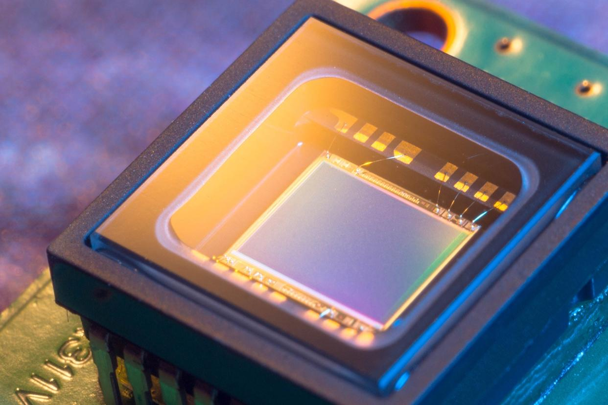
The starting point of the Camera data chain is the Image Sensor, whose main role is to convert the optical image captured by the lens into digital image data. Taking the Sony IMX219 as an example, the sensor internally mainly contains a photosensitive pixel array, analog signal processing circuits, an analog-to-digital converter (ADC), and a MIPI CSI-2 data output interface.
When light is projected onto the sensor surface through the lens, the whole image acquisition process can be divided into the following steps:
- Photoelectric Conversion: The photosensitive pixel array receives light, and each pixel generates a corresponding charge based on the number of photons received, thereby converting the optical signal into an electrical signal.
- Analog Signal Processing: The sensor reads the accumulated charge of each pixel, converts it into a voltage signal, and performs necessary amplification and noise suppression.
- Analog-to-Digital Conversion: The ADC converts the analog voltage into digital pixel values. For example, in RAW10 mode, each pixel uses 10 bits to represent its sampled result.
- Data Transmission: The sensor packages the digital pixel data according to the MIPI CSI-2 protocol and transmits it through the MIPI D-PHY physical interface to the Jetson's NVCSI module.
3.1 Understanding RAW Bayer
The color images we see every day usually contain three color channels: Red, Green, and Blue. But for a typical Bayer sensor, a single pixel usually only records the sampled value of one color. For example, the RGGB arrangement is shown in the figure below.
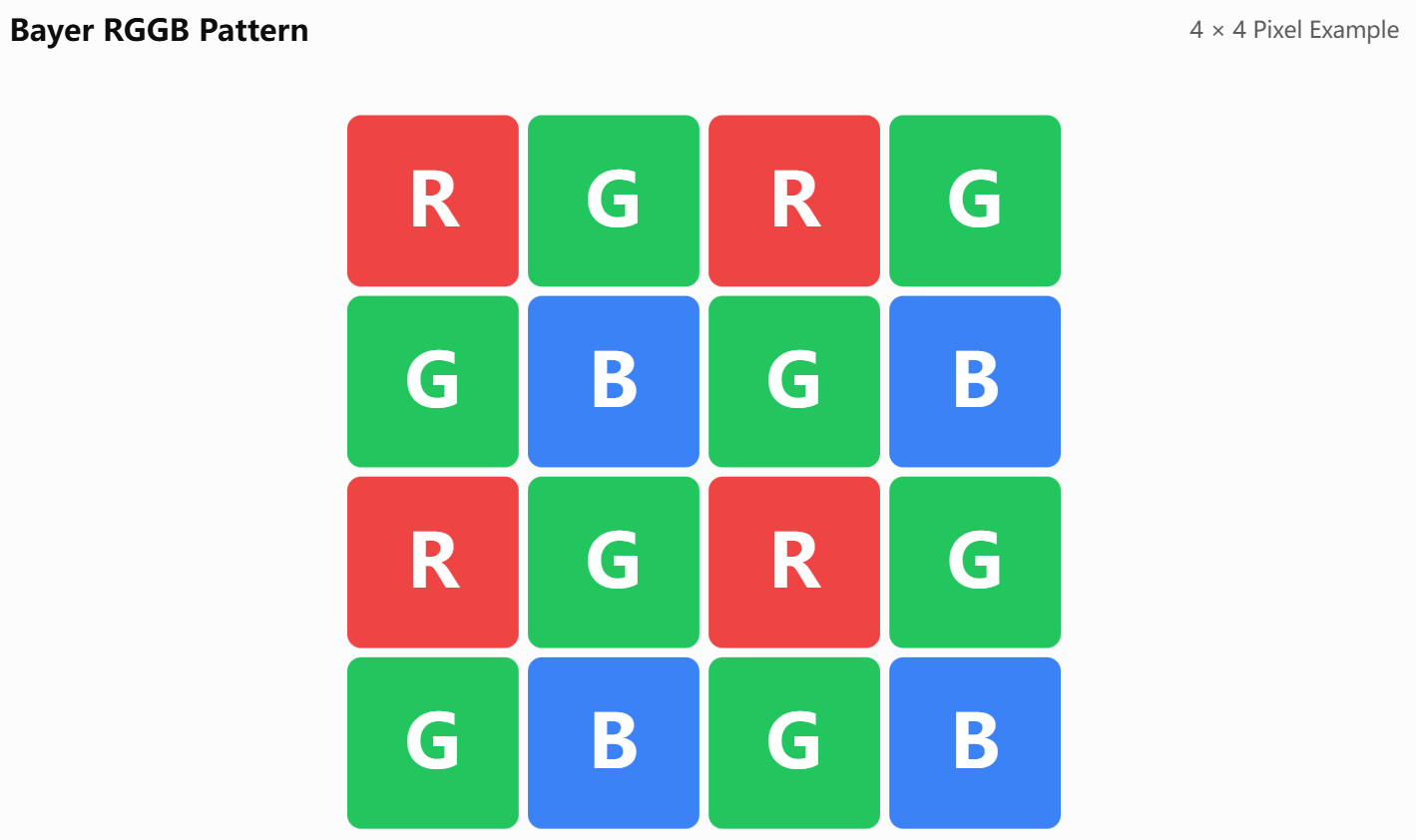
Therefore, the RAW Bayer data output by the sensor is not equivalent to a complete RGB color image. To obtain a complete color image, the color information needs to be reconstructed through algorithms such as Demosaicing.
3.2 What Does RAW10 Mean?
The common output mode of the IMX219 uses 10-bit Bayer RAW. RAW10 means each pixel contains 10 bits of valid raw sampled information.
For example, a 1920 × 1080 image has a total of:
1920 × 1080 = 2,073,600 pixels
Counting only the valid pixel data, the data volume required for RAW10 is:
2,073,600 × 10 / 8 = 2,592,000 Bytes
which is about 2.47 MiB.
However, this is only the theoretical data volume of valid pixels, and it does not mean the RAW file saved in Jetson memory must be exactly this size. The packing method of CSI-2 data, the memory layout of the VI output, and line alignment may all affect the actual final Buffer size. This will be further verified in the RAW capture experiment.
3.3 The Sensor's Control Interface and Data Interface
The IMX219 has two interfaces with different purposes:
- Control interface: I2C, used to configure registers such as exposure time, analog gain, frame rate, and operating modes.
- Data interface: MIPI CSI-2, used to continuously output image pixel data.
The two are independent of each other.
For example, the Jetson successfully accessing the IMX219 over I2C only shows that the Sensor control communication may have been established.
It cannot prove that the Sensor has started outputting images normally, nor can it prove that CSI and VI have successfully captured data.
3.4 Real-Device Experiment 1: Recognizing the Sony IMX219
First, install the v4l2 tools:
sudo apt update
sudo apt install v4l-utils -y
v4l2-ctl --version
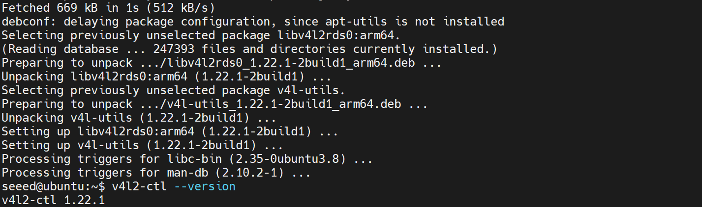
Then run:
ls -l /dev/video*
v4l2-ctl --list-devices
A properly registered CSI Camera usually shows the corresponding Video Device.
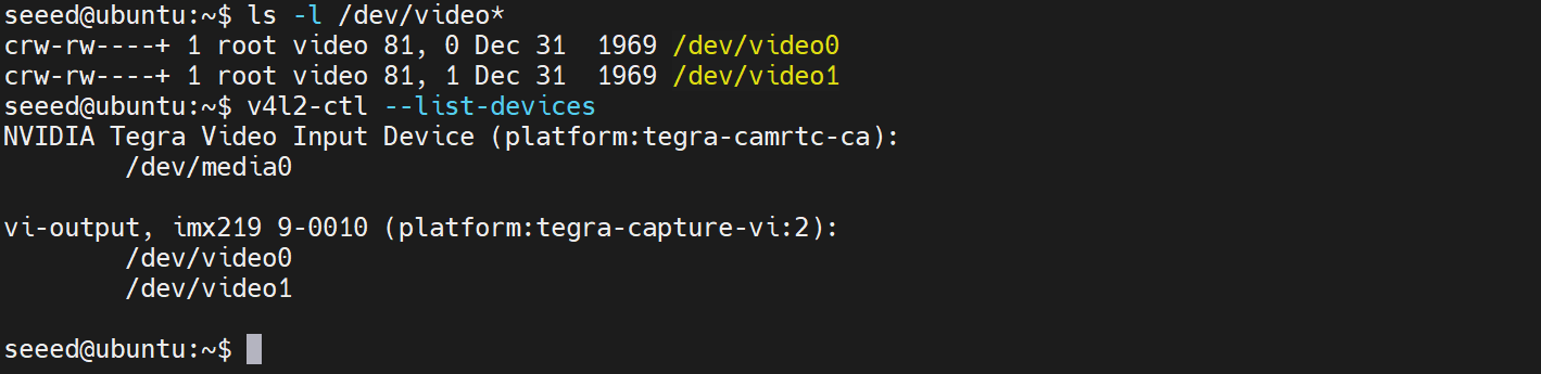
Here you can see that the Jetson recognized an IMX219 camera and created two video device nodes. Next, let's look at the detailed device information:
v4l2-ctl -d /dev/video0 --all
v4l2-ctl output log
seeed@ubuntu:~$ v4l2-ctl -d /dev/video0 --all
Driver Info:
        Driver name      : tegra-video
        Card type        : vi-output, imx219 9-0010
        Bus info         : platform:tegra-capture-vi:2
        Driver version   : 5.15.148
        Capabilities     : 0x84a00001
                Video Capture
                Metadata Capture
                Streaming
                Extended Pix Format
                Device Capabilities
        Device Caps      : 0x04200001
                Video Capture
                Streaming
                Extended Pix Format
Media Driver Info:
        Driver name      : tegra-camrtc-ca
        Model            : NVIDIA Tegra Video Input Device
        Serial           :
        Bus info         :
        Media version    : 5.15.148
        Hardware revision: 0x00000003 (3)
        Driver version   : 5.15.148
Interface Info:
        ID               : 0x0300000b
        Type             : V4L Video
Entity Info:
        ID               : 0x00000009 (9)
        Name             : vi-output, imx219 9-0010
        Function         : V4L2 I/O
        Pad 0x0100000a   : 0: Sink
          Link 0x0200000f: from remote pad 0x1000006 of entity '13e00000.host1x:nvcsi@15a00000-' (Unknown sub-device (0002000a)): Data, Enabled
Priority: 2
Video input : 0 (Camera 2: ok)
Format Video Capture:
        Width/Height      : 3280/2464
        Pixel Format      : 'RG10' (10-bit Bayer RGRG/GBGB)
        Field             : None
        Bytes per Line    : 6592
        Size Image        : 16242688
        Colorspace        : sRGB
        Transfer Function : Default (maps to sRGB)
        YCbCr/HSV Encoding: Default (maps to ITU-R 601)
        Quantization      : Default (maps to Full Range)
        Flags             :
Streaming Parameters Video Capture:
        Capabilities     : timeperframe
        Frames per second: 21.000 (21/1)
        Read buffers     : 0

Camera Controls

                     group_hold 0x009a2003 (bool)   : default=0 value=0 flags=execute-on-write
                    sensor_mode 0x009a2008 (int64)  : min=0 max=5 step=1 default=0 value=0 flags=slider
                           gain 0x009a2009 (int64)  : min=16 max=171 step=1 default=16 value=16 flags=slider
                       exposure 0x009a200a (int64)  : min=13 max=683710 step=1 default=2495 value=13 flags=slider
                     frame_rate 0x009a200b (int64)  : min=2000000 max=21000000 step=1 default=21000000 value=2000000 flags=slider
           sensor_configuration 0x009a2032 (u32)    : min=0 max=4294967295 step=1 default=0 dims=[22] flags=read-only, volatile, has-payload
         sensor_mode_i2c_packet 0x009a2033 (u32)    : min=0 max=4294967295 step=1 default=0 dims=[1026] flags=read-only, volatile, has-payload
      sensor_control_i2c_packet 0x009a2034 (u32)    : min=0 max=4294967295 step=1 default=0 dims=[1026] flags=read-only, volatile, has-payload
                    bypass_mode 0x009a2064 (intmenu): min=0 max=1 default=0 value=0 (0 0x0)
                                0: 0 (0x0)
                                1: 1 (0x1)
                override_enable 0x009a2065 (intmenu): min=0 max=1 default=0 value=0 (0 0x0)
                                0: 0 (0x0)
                                1: 1 (0x1)
                   height_align 0x009a2066 (int)    : min=1 max=16 step=1 default=1 value=1
                     size_align 0x009a2067 (intmenu): min=0 max=2 default=0 value=0 (1 0x1)
                                0: 1 (0x1)
                                1: 65536 (0x10000)
                                2: 131072 (0x20000)
               write_isp_format 0x009a2068 (int)    : min=1 max=1 step=1 default=1 value=1
       sensor_signal_properties 0x009a2069 (u32)    : min=0 max=4294967295 step=1 default=0 dims=[30][18] flags=read-only, has-payload
        sensor_image_properties 0x009a206a (u32)    : min=0 max=4294967295 step=1 default=0 dims=[30][16] flags=read-only, has-payload
      sensor_control_properties 0x009a206b (u32)    : min=0 max=4294967295 step=1 default=0 dims=[30][36] flags=read-only, has-payload
              sensor_dv_timings 0x009a206c (u32)    : min=0 max=4294967295 step=1 default=0 dims=[30][16] flags=read-only, has-payload
               low_latency_mode 0x009a206d (bool)   : default=0 value=0
               preferred_stride 0x009a206e (int)    : min=0 max=65535 step=1 default=0 value=0
    override_capture_timeout_ms 0x009a206f (int)    : min=-1 max=2147483647 step=1 default=2500 value=2500
                   sensor_modes 0x009a2082 (int)    : min=0 max=30 step=1 default=30 value=5 flags=read-only
seeed@ubuntu:~$ v4l2-ctl -d /dev/video1 --all
Driver Info:
        Driver name      : tegra-embedded
        Card type        : tegra-capture-vi-metadata-2
        Bus info         : platform:tegra-capture-vi:2
        Driver version   : 5.15.148
        Capabilities     : 0x84a00001
                Video Capture
                Metadata Capture
                Streaming
                Extended Pix Format
                Device Capabilities
        Device Caps      : 0x04a00000
                Metadata Capture
                Streaming
                Extended Pix Format
Media Driver Info:
        Driver name      : tegra-camrtc-ca
        Model            : NVIDIA Tegra Video Input Device
        Serial           :
        Bus info         :
        Media version    : 5.15.148
        Hardware revision: 0x00000003 (3)
        Driver version   : 5.15.148
Interface Info:
        ID               : 0x03000013
        Type             : V4L Video
Entity Info:
        ID               : 0x00000011 (17)
        Name             : tegra-capture-vi-metadata-2
        Function         : V4L2 I/O
        Pad 0x01000012   : 0: Sink
Priority: 2
Format Metadata Capture:
        Sample Format   : 'G2XX' (Orbbec G2xx UVC Metadata)
        Buffer Size     : 96
This command can provide the driver information, capture capabilities, image format, and some working parameters of the current device.
If the Sensor driver fails to load, you can look for clues in the system log. The log may contain I2C access failures, power, or Probe related errors. For the log capture command, refer to the command below:
sudo dmesg | grep -i imx219
4. MIPI CSI-2: How Does the Image Get from the Sensor to the Jetson?
After the Sensor generates the image, it needs to send the data to the Jetson through a physical interface. The IMX219 outputs images through the MIPI CSI-2 interface. CSI-2 is a high-speed serial protocol used for camera data transmission, widely used in embedded systems.
4.1 CSI-2 and D-PHY
CSI-2 defines the transmission protocol of camera data, while D-PHY is the common physical layer implementation. For a typical D-PHY connection, the Camera transmits information through differential data lanes and a clock lane. What CSI-2 sends is not just pixel data; it also includes packet information used to distinguish frames, data types, and channels, such as: Frame Start, Frame End, Data Type, Virtual Channel, Pixel Payload, etc. The receiver needs to correctly identify this information in order to restore the continuous data stream into the corresponding image frames.
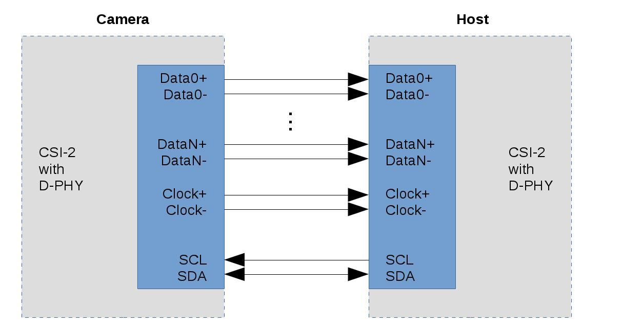
Image source: https://blog.zhaw.ch/high-performance/2017/02/28/mipi-csidsi-interface-for-general-purpose-data-acquisition/
4.2 How Do the Number of CSI Lanes Affect Bandwidth?
Take 1920 × 1080, 30 FPS, RAW10 as an example.
The theoretical valid pixel data rate per second is:
1920 × 1080 × 30 × 10 = 622.08 Mbps
The reComputer Classic J3010 uses two Data Lanes, so the valid pixel data rate per lane after even distribution is about:
311.04 Mbps/Lane
This means that under the capture conditions above, each Data Lane needs to carry about 311 Mbps of valid pixel data per second on average. But this is not the actual lane rate requirement. The actual calculation also needs to consider the CSI-2 packet overhead, sensor timing, and the corresponding bandwidth margin.
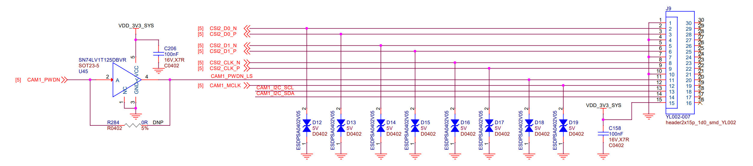
Image source: https://files.seeedstudio.com/wiki/J401/reComputer_J401_SCH_V1.0.pdf
5. NVCSI: How Does the Jetson Receive Camera Data?
When the IMX219 sends data to the Jetson through MIPI CSI-2, the data enters NVCSI. It is the Camera receiving module inside the Jetson SoC. Here we need to distinguish two concepts: CSI-2 is a data transmission protocol, while NVCSI is the hardware module inside the Jetson that implements the corresponding data receiving function. NVCSI receives CSI-2 data from the external Sensor, and receives, parses, and routes it according to the configuration.
5.1 NVCSI and Virtual Channel
For a single camera, the data flow is usually relatively simple. But in scenarios where multiple cameras share a CSI data link, Virtual Channel may be used. Virtual Channel allows different logical data streams to be transmitted on the same CSI-2 link. For example:
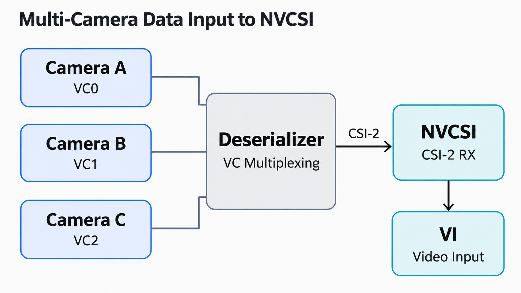
In a GMSL2 camera system, multiple Sensors can pass through Serializer and Deserializer to feed data into the Jetson, and then different video streams are distinguished through Virtual Channel. Therefore, in multi-camera debugging, the mapping of CSI Port, Virtual Channel, and VI Channel is very important.
5.2 Real-Device Experiment 2: Viewing the Camera Media Graph
The Linux Media Controller Framework can represent the connection relationships between multimedia devices as a topology graph.
On the J3010, query the Media Devices registered in the system:
ls /dev/media*
# If a media0 device exists, view its details
media-ctl -d /dev/media0 -p
# Where:
# -d /dev/media0: specifies the Media Device to view.
# -p: prints the Media Controller topology information.
Returned log
seeed@ubuntu:~$ ls /dev/media*
/dev/media0
seeed@ubuntu:~$ media-ctl -d /dev/media0 -p
Media controller API version 5.15.148

Media device information
------------------------
driver          tegra-camrtc-ca
model           NVIDIA Tegra Video Input Device
serial
bus info
hw revision     0x3
driver version  5.15.148

Device topology
- entity 1: 13e00000.host1x:nvcsi@15a00000- (2 pads, 0 link)
            type V4L2 subdev subtype Unknown flags 0
            device node name /dev/v4l-subdev0
        pad0: Sink
        pad1: Source

- entity 4: 13e00000.host1x:nvcsi@15a00000- (2 pads, 2 links)
            type V4L2 subdev subtype Unknown flags 0
            device node name /dev/v4l-subdev1
        pad0: Sink
                <- "imx219 9-0010":0 [ENABLED]
        pad1: Source
                -> "vi-output, imx219 9-0010":0 [ENABLED]

- entity 7: imx219 9-0010 (1 pad, 1 link)
            type V4L2 subdev subtype Sensor flags 0
            device node name /dev/v4l-subdev2
        pad0: Source
                [fmt:SRGGB10_1X10/3280x2464@1/21 field:none colorspace:srgb]
                -> "13e00000.host1x:nvcsi@15a00000-":0 [ENABLED]

- entity 9: vi-output, imx219 9-0010 (1 pad, 1 link)
            type Node subtype V4L flags 0
            device node name /dev/video0
        pad0: Sink
                <- "13e00000.host1x:nvcsi@15a00000-":1 [ENABLED]

- entity 17: tegra-capture-vi-metadata-2 (1 pad, 0 link)
             type Node subtype V4L flags 0
             device node name /dev/video1
        pad0: Sink

seeed@ubuntu:~$
Combined with the actual log, the current IMX219 Media Controller topology can be simplified into the following diagram.
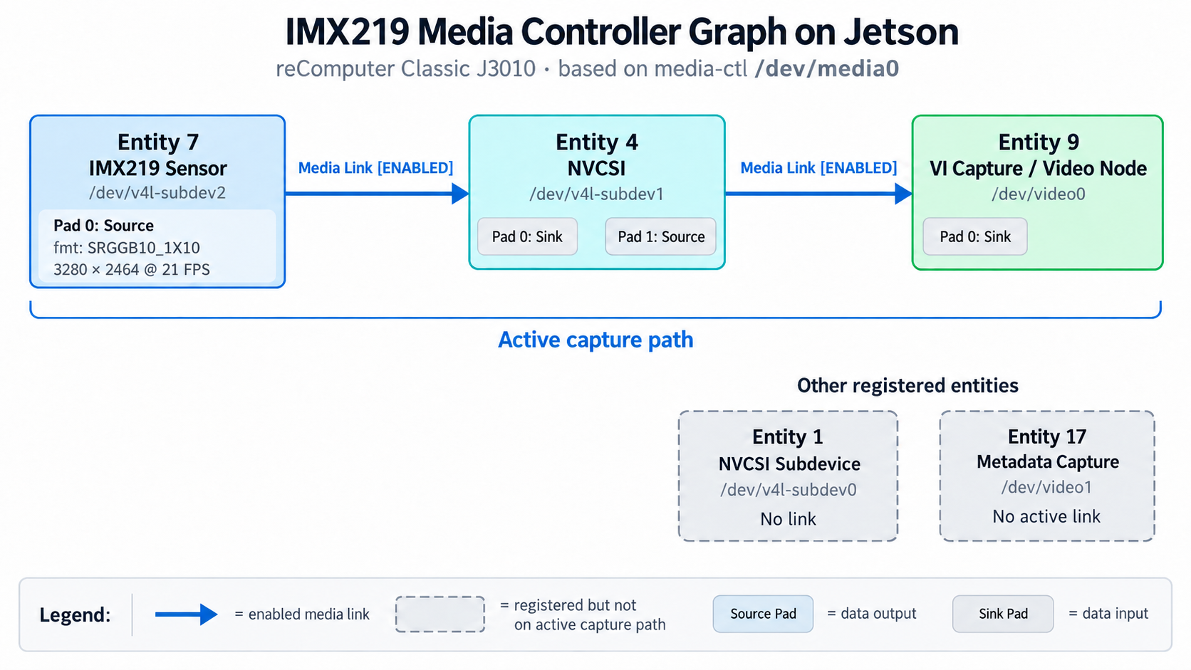
Note that the Media Graph describes the topology registered in the kernel; by itself it cannot prove that high-speed CSI data is being transmitted normally.
Besides the complete data chain, the current log also contains two additional Media Entities.
Unconnected NVCSI Sub-device
entity 1: 13e00000.host1x:nvcsi@15a00000-
    (2 pads, 0 link)

    device node name /dev/v4l-subdev0
This NVCSI Sub-device currently has no Media Link established, so it does not belong to the connected IMX219 capture path above.
Metadata Capture Node
entity 17: tegra-capture-vi-metadata-2
    (1 pad, 0 link)

    device node name /dev/video1
Combined with the result of v4l2-ctl -d /dev/video1 --all, it can be confirmed that /dev/video1 is a Metadata Capture device, not a normal image capture node for a second camera.
This shows that, in Linux, the number of /dev/video* nodes does not necessarily equal the number of cameras actually connected. Developers should determine the actual function of a device by combining V4L2 Device Capabilities and the Media Graph.
6. VI: How Does CSI Data Become Image Frames?
NVCSI is responsible for receiving CSI data, while the main responsibility of VI (Video Input) is to complete frame capture according to the configuration and write the image data into memory. In a typical V4L2 RAW capture path:
IMX219 -> MIPI CSI-2 -> NVCSI -> VI -> Memory Buffer -> V4L2 -> Application
VI transfers image data through mechanisms such as DMA, avoiding the CPU having to move camera data pixel by pixel.
6.1 Frame and Buffer
For video capture, applications usually do not directly read the CSI serial signal. Instead, they request image Buffers through V4L2, start Streaming, and read the corresponding Buffer after capture completes.
The simplified capture process is as follows:

This is also the reason why V4L2 uses Buffer mechanisms such as MMAP.
6.2 Real-Device Experiment 3: Capturing RAW Data
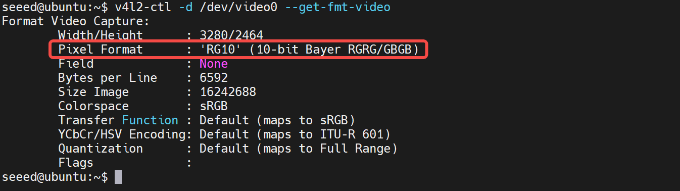
First, check the current image format of the IMX219:
v4l2-ctl -d /dev/video0 --get-fmt-video
Run a 100-frame RAW capture test:
v4l2-ctl -d /dev/video0 \
  --stream-mmap \
  --stream-count=100 \
  --verbose
If frames can be captured continuously, it means that under the current mode, the Sensor, NVCSI, VI, and V4L2 Buffer path already have basic data capture capability.
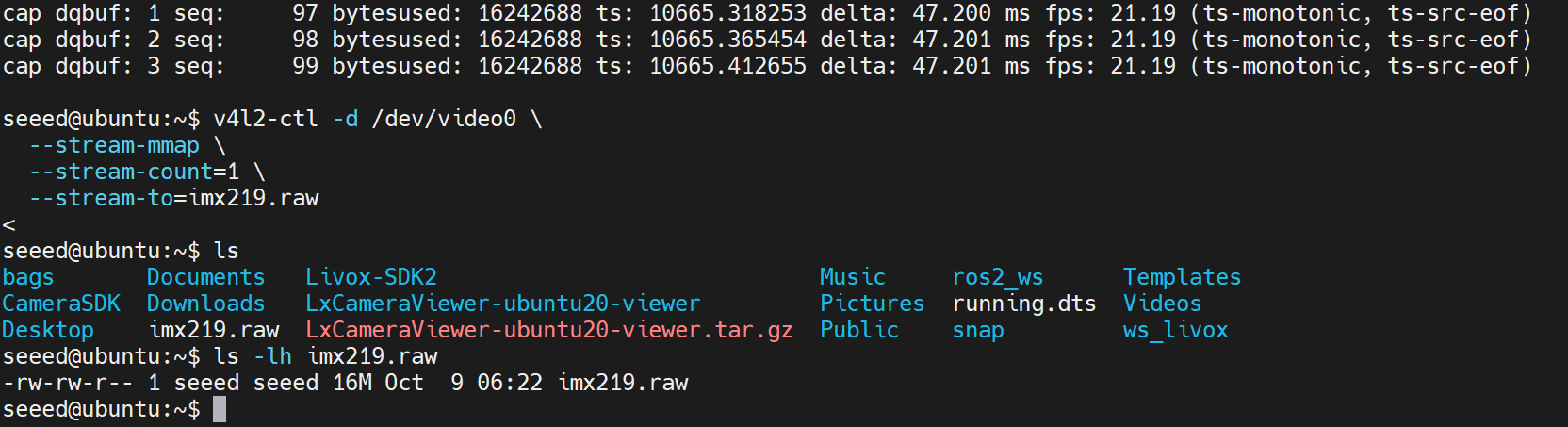
Then save one RAW frame:
v4l2-ctl -d /dev/video0 \
  --stream-mmap \
  --stream-count=1 \
  --stream-to=imx219.raw
Check the file size:
ls -lh imx219.raw
6.3 Why Doesn't RAW10 Necessarily Occupy Only 10 Bits?
In the Jetson Camera data chain, we need to distinguish the MIPI CSI-2 transmission format from the data format VI writes into memory. The IMX219 transmits RAW10 data over MIPI CSI-2, where each valid pixel contains 10 bits of information. But under the current V4L2 capture format, VI stores each pixel in a 16-bit (2 Bytes) container, with row alignment applied.
Therefore, the actual Buffer size cannot simply be calculated as 10 bit/Pixel.
Let's analyze based on the log screenshot above. The current resolution is 3280 × 2464:
- Calculated as compact RAW10 packing: 3280 × 2464 × 10 / 8 = 10,102,400 Bytes, about 9.63 MiB.
- Calculated as 16-bit container: 3280 × 2464 × 2 = 16,163,840 Bytes, about 15.42 MiB.
- Calculated from the actual Bytes Per Line: 6592 × 2464 = 16,242,688 Bytes, about 15.49 MiB.
When 100 frames were successfully captured, the actual frame rate was about 21.19 FPS, and each frame Buffer used 16,242,688 Bytes.
The single-frame RAW image saved afterwards was about 16 MB, consistent with the capture Buffer size.
Conclusion: the 10 bits in RAW10 describe the effective data bit depth of each pixel, and do not mean the image only occupies 10 bit/Pixel in memory. Under the current Jetson VI capture configuration, RAW10 is stored in a 16-bit container and is affected by Bytes Per Line alignment, so the actual memory usage is higher than the compactly packed RAW10 data volume.
6.4 How to Display RAW Data?
After successfully capturing the RAW image through V4L2, we obtained the imx219.raw file. But RAW Bayer data is not an ordinary RGB color image and cannot be correctly displayed by a regular image viewer. To convert it into a color image, you first need to read the pixel data according to the actual memory layout, and then recover the RGB image through the Demosaicing algorithm.
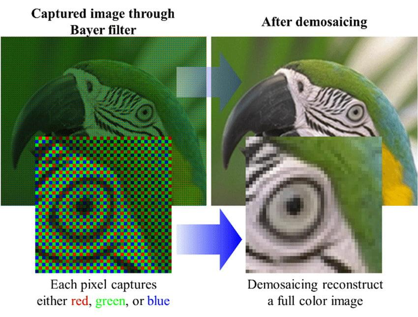
Image source: https://jetsonhacks.com/2022/01/13/in-depth-cameras/
Based on the screenshot above, we can determine the following characteristics of the current RAW image:
- The image resolution is 3280 × 2464.
- The Bayer arrangement is RGGB, with 10-bit valid data per pixel.
- V4L2 stores each pixel in a 16-bit container.
- Each row actually occupies 6592 Bytes, while the valid pixel data only takes up 6560 Bytes.
It can be determined that each row has an extra 32 Bytes of Padding. When reading the RAW file, you must consider the row Padding and cannot simply reshape all the data into a 3280 × 2464 two-dimensional array.
The following uses Python + OpenCV for the conversion:
import cv2
import numpy as np

# IMX219 V4L2 capture configuration
WIDTH = 3280
HEIGHT = 2464
BYTES_PER_LINE = 6592

# 1. Read RAW data as 16-bit little-endian
raw = np.fromfile("imx219.raw", dtype="<u2")

expected = HEIGHT * BYTES_PER_LINE // 2
assert raw.size == expected, "RAW file size mismatch"

# 2. Restore row layout and remove padding
raw = raw.reshape(HEIGHT, BYTES_PER_LINE // 2)
raw = raw[:, :WIDTH]

# 3. Extract 10-bit values for preview
# Experimental decoding based on observed image structure
raw10 = raw >> 6

# 4. Normalize brightness for visualization
low, high = np.percentile(raw10, [1, 99.5])

if high <= low:
    raise ValueError("Invalid RAW intensity range")

normalized = np.clip(
    (raw10.astype(np.float32) - low) / (high - low),
    0, 1
)

# 5. Apply gamma correction
gamma = 0.65
raw8 = (np.power(normalized, gamma) * 255).astype(np.uint8)

# 6. Save grayscale preview
cv2.imwrite("imx219-gray.png", raw8)

# 7. Bayer demosaicing
# RGGB Bayer pattern
bgr = cv2.cvtColor(raw8, cv2.COLOR_BayerRG2BGR)

# 8. Save color image
cv2.imwrite("imx219-demosaic.png", bgr)

print("RAW conversion completed")
print("Output: imx219-gray.png")
print("Output: imx219-demosaic.png")
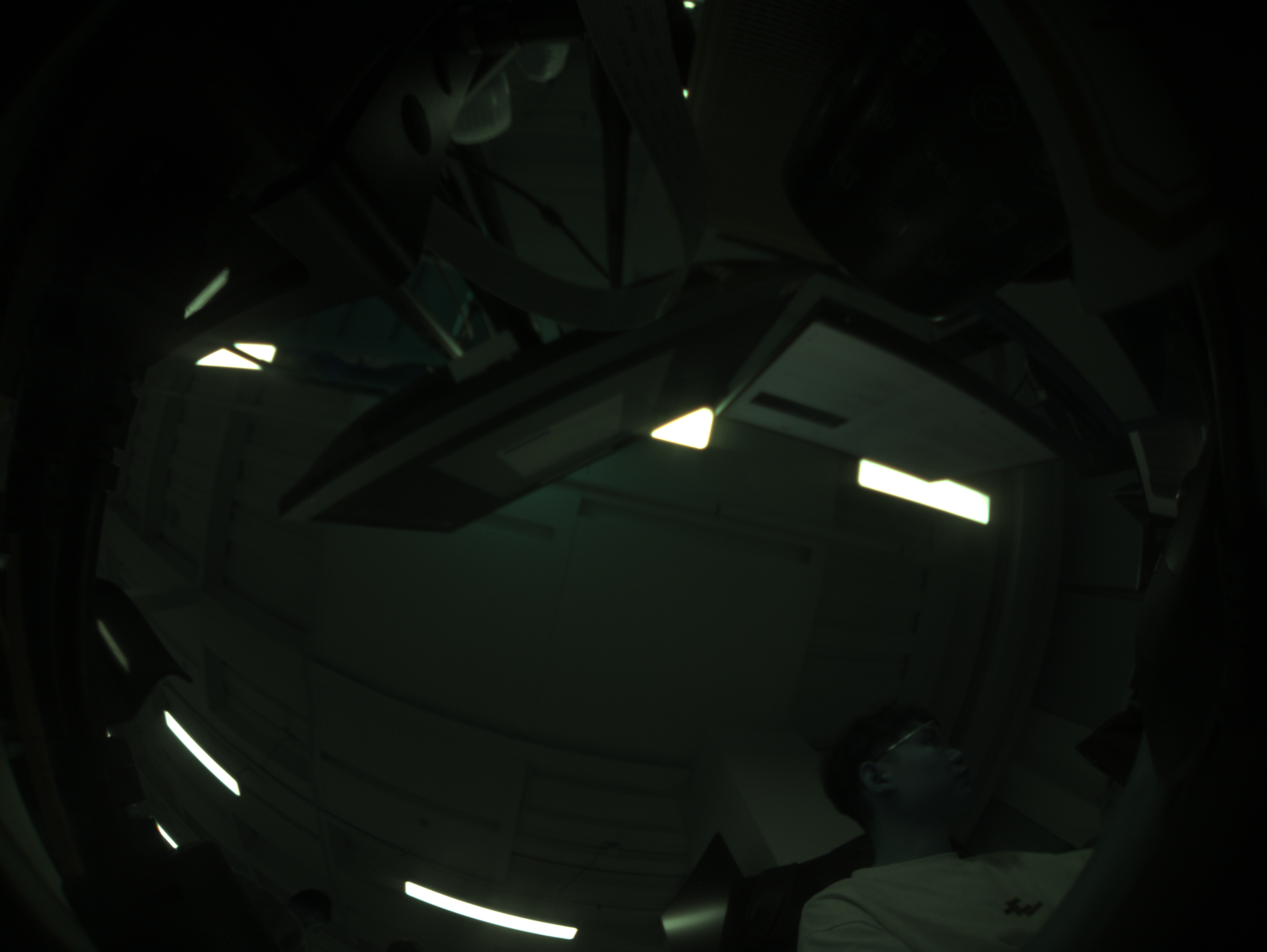
The image converted by OpenCV is not equivalent to the image processed by the NVIDIA ISP. Due to the lack of complete white balance, color correction, noise reduction, and other processing, the final image may be darker in brightness and inaccurate in color.
7. ISP: How Does RAW Data Become a Color Image?
The ISP (Image Signal Processor) is responsible for converting the Sensor's raw image into an image suitable for display, encoding, or subsequent algorithms. For Bayer RAW, typical image processing functions include:
| Function | Role |
|---|---|
| Black Level Correction | Black level correction |
| Demosaicing | Bayer color reconstruction |
| White Balance | White balance |
| Color Correction | Color correction |
| Noise Reduction | Image noise reduction |
| Tone Mapping | Brightness and dynamic range processing |
| Sharpening | Image sharpening |
At the same time, the Jetson Camera Framework can also coordinate 3A control:
- AE: Automatic Exposure
- AWB: Automatic White Balance
- AF: Automatic Focus
Note that 3A does not all belong to the ISP pixel processing itself. For example, AE needs to adjust exposure and gain through Sensor Control, while AF depends on the sensor module having a controllable focus mechanism.
7.1 Why Does the ISP Need Tuning?
Even if two Cameras use the same Sensor, it does not mean that after the ISP they will produce exactly the same image. This is because image quality depends not only on the Sensor, but also on factors such as the Lens, IR Filter, Sensor calibration parameters, and actual lighting conditions. These differences may cause the images to differ in brightness, color, white balance, and noise performance.
Therefore, it is necessary to use ISP Tuning to adjust the relevant image processing parameters for a specific Camera Module, such as white balance, color correction, noise reduction, and sharpening, in order to obtain more accurate and stable image results. In short, the ISP is responsible for processing images, while ISP Tuning decides how to optimize the processing effect for different cameras.
7.2 Real-Device Experiment 4: Capturing ISP Images Through Argus
In the previous experiments, we obtained the RAW10 data of the IMX219 through V4L2 and used OpenCV to complete basic Demosaicing. Next, we use the NVIDIA Argus Camera Framework to let the image go through the Jetson's ISP, and observe the difference in image quality between the two approaches.
This experiment uses the reComputer Classic J3010 + IMX219, connecting to the Jetson remotely via SSH to complete image capture.
step1. Check the GStreamer plugin:
gst-inspect-1.0 nvarguscamerasrc
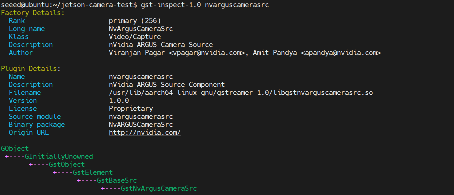
If the plugin information is displayed normally, it means GStreamer can find the plugin.
step2. Test image capture through Argus
In an SSH environment, especially when X11 Forwarding is enabled, environment variables such as DISPLAY may affect the EGLStream initialization of NVIDIA Argus. If you are accessing the Jetson device remotely, use env -u to temporarily remove the relevant environment variables:
env -u DISPLAY -u WAYLAND_DISPLAY -u LD_LIBRARY_PATH \
gst-launch-1.0 -e \
  nvarguscamerasrc sensor-id=0 num-buffers=100 ! \
  'video/x-raw(memory:NVMM),width=1920,height=1080,framerate=30/1,format=NV12' ! \
  fakesink
Where:
nvarguscamerasrc: obtains Camera images through NVIDIA Argus.sensor-id=0: selects the first available Argus Sensor.num-buffers=100: captures 100 frames.memory:NVMM: uses NVIDIA multimedia buffers.format=NV12: specifies the output image format.fakesink: receives and discards the image without displaying or saving it.
Using env -u here only affects the current command and does not permanently modify the system environment variables.
If the program captures normally and finishes without any error in the log, it means the current Camera can output basic images through Argus.
step3. Save the ISP-processed color image
After confirming that Argus capture works normally, run the following command to save a JPEG image:
env -u DISPLAY -u WAYLAND_DISPLAY -u LD_LIBRARY_PATH \
gst-launch-1.0 -e \
  nvarguscamerasrc sensor-id=0 num-buffers=1 ! \
  'video/x-raw(memory:NVMM),width=1920,height=1080,framerate=30/1,format=NV12' ! \
  nvvidconv ! \
  'video/x-raw,format=I420' ! \
  jpegenc ! \
  filesink location=imx219-isp.jpg
In this Pipeline:
- nvarguscamerasrc: calls the Camera capture and ISP processing path through Argus.
- nvvidconv: converts the NVMM image into a memory and pixel format supported by the subsequent encoder.
- jpegenc: encodes the image as JPEG.
- filesink: saves the JPEG data to a file.
After saving, check it:
ls -lh imx219-isp.jpg
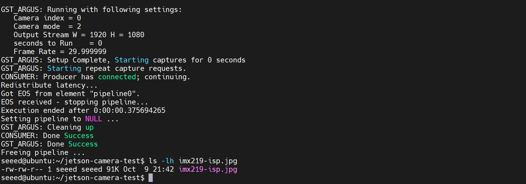
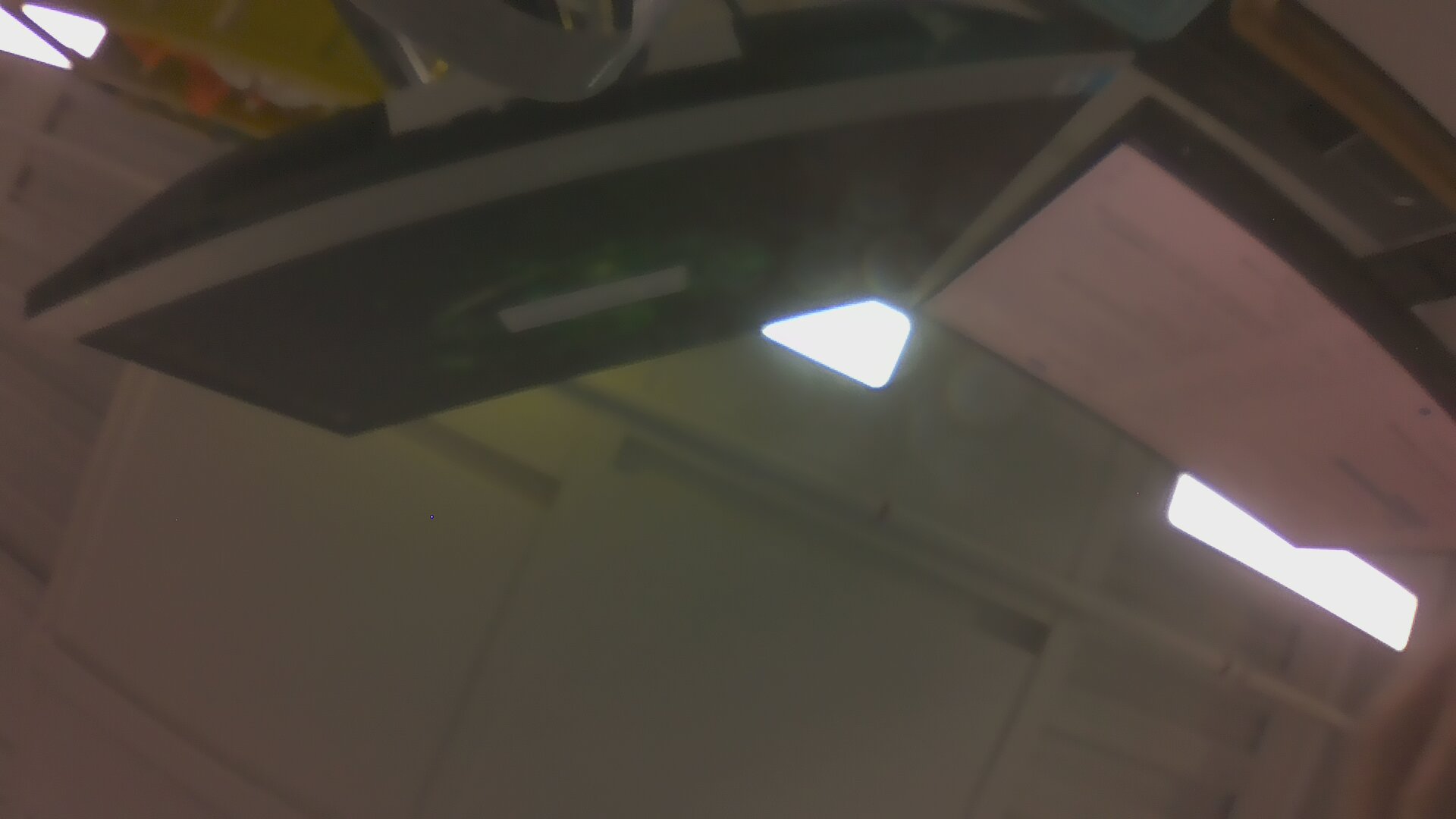
Compared with the OpenCV Demosaic image above, the ISP-processed image has more complete color, brightness, and noise optimization. The conclusion here is: V4L2 is mainly used to obtain the Sensor's RAW image, while Argus can call the NVIDIA ISP to generate color images with more complete image processing.
Note that the saved image still has blurriness and purple fringing issues, because the lens focus and ISP parameters have not been adjusted yet.
8. V4L2 and Argus: Two Different Camera Data Paths
Through the previous experiments, we have used two different ways to capture images. One is V4L2, and the other is Argus. Both can use the Jetson's underlying Camera hardware, but the usage paths and applicable scenarios are different.
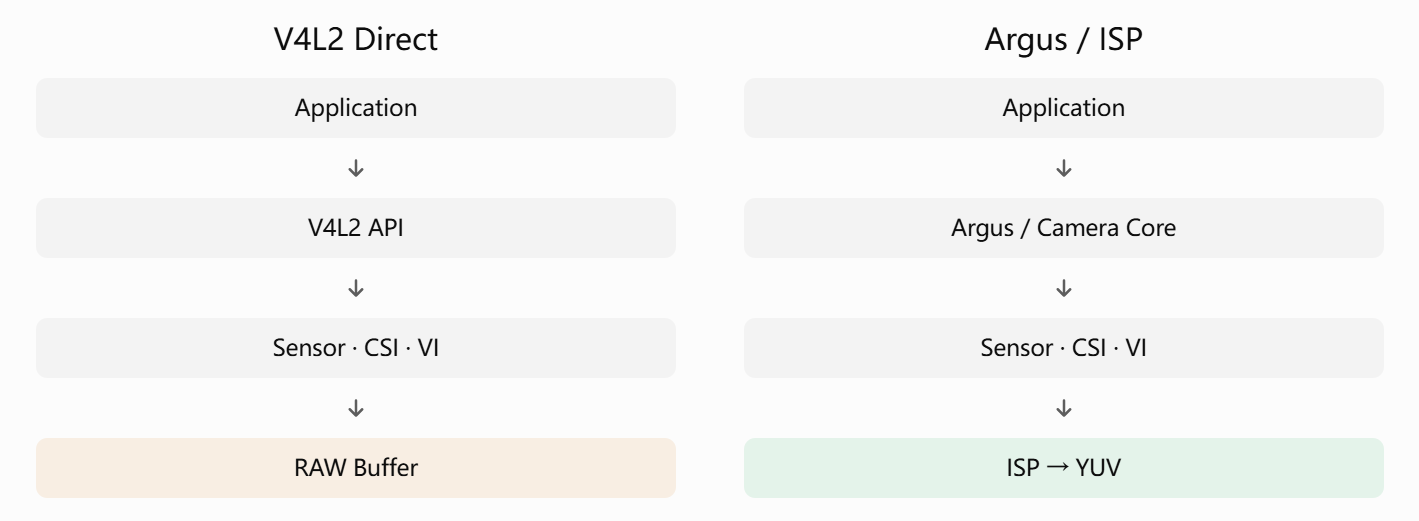
8.1 V4L2 RAW Capture
V4L2 can directly obtain the RAW data output by the Bayer Sensor without going through the Jetson ISP.
This approach is suitable for Sensor driver development, CSI Camera debugging, RAW data analysis, and custom image processing algorithm development.
8.2 Argus ISP Capture
Argus is a Camera Framework provided by NVIDIA. It can combine Sensor Control and the ISP to perform demosaicing, white balance, color correction, noise reduction, and other processing on RAW images, and output image formats such as NV12.
This approach is more suitable for real-time camera preview, video capture, and vision applications that require good image quality.
8.3 Comparison
| Item | V4L2 RAW | Argus ISP |
|---|---|---|
| Typical output | RAW Bayer | NV12 / YUV |
| Uses ISP | Not required | Can be used |
| Sensor Control | V4L2 Controls | Argus Camera Core |
| Applicable scenarios | Driver debugging, RAW analysis | Color images, video applications |
| Common tools | v4l2-ctl | nvarguscamerasrc |
| ISP Tuning required | Not needed for RAW capture | Image quality may depend on Tuning |
Note that V4L2 is not limited to outputting RAW data. "V4L2 RAW" here specifically refers to the scenario of directly capturing the Bayer Sensor's raw data through the Jetson VI.
8.4 Why Does Argus Fail While V4L2 Works?
Even if V4L2 can capture RAW images normally, it does not mean Argus will necessarily work.
This is because Argus not only depends on the underlying Sensor, NVCSI, and VI, but also involves Camera Core, Sensor Control, ISP configuration, NVIDIA Buffer management, and other aspects.
Therefore, when V4L2 works but Argus fails, you can prioritize checking:
- Camera Core configuration: whether the Sensor Mode and related parameters are correct.
- Sensor Controls: whether controls such as exposure and gain work normally.
- Argus service: whether
nvargus-daemonhas any exceptions. - Runtime environment: whether SSH X11 Forwarding, EGL, and dynamic library environments conflict.
9. Device Tree: How Does the Jetson Know Where the Camera Is Connected?
From the hardware perspective, the Sensor connects to the Jetson through the CSI interface. But simply connecting the cable is not enough for the Camera to work automatically. The Jetson also needs to know the connection relationship and the specific working mode of the Sensor. This information is usually provided by the Device Tree and the corresponding Sensor Driver.
9.1 Camera Device Tree
Taking the reComputer Classic J401 with an IMX219 as an example, Seeed Studio provides the corresponding Device Tree configuration in the Linux_for_Tegra repository. It mainly involves two files:
① J401 carrier board configuration file recomputer-orin-j401.conf
This file specifies the base Device Tree used by the J401 and references the IMX219 Camera Overlay:
② IMX219 Camera Overlay tegra234-p3767-camera-p3768-imx219-dual-seeed.dts
This file configures two IMX219 Cameras for the J401, defining hardware connection information such as the I2C MUX, GPIO, and CSI interface, and references the base IMX219 Sensor configuration.
Note that this is only part of the configuration in the Overlay. The complete Sensor Mode also includes parameters such as resolution, CSI lane count, pixel bit depth, and clocks.
9.2 Sensor Mode: How Does the IMX219 Transmit Images?
The Sensor Mode in the Device Tree is used to describe the specific working method of the camera. In this J401 real-device experiment, we read the following parameters of the IMX219 mode0 from the runtime Device Tree:
mode0 {
    num_lanes = "2";
    tegra_sinterface = "serial_a";
    phy_mode = "DPHY";

    mode_type = "bayer";
    pixel_phase = "rggb";

    active_w = "3280";
    active_h = "2464";

    csi_pixel_bit_depth = "10";
    pix_clk_hz = "182400000";
};
The above are the key fields extracted and organized from the J401 runtime Device Tree, not the complete Sensor Mode configuration.
9.3 Real-Device Experiment 5: Viewing the Device Tree in Use
What is saved in GitHub is the Device Tree source code, while the Jetson actually uses the Device Tree after the Overlay has been loaded and applied during the boot process. We can directly view the currently effective configuration over SSH.
Here we directly search for properties containing imx219 in the runtime Device Tree:
sudo grep -rla 'imx219' /proc/device-tree 2>/dev/null
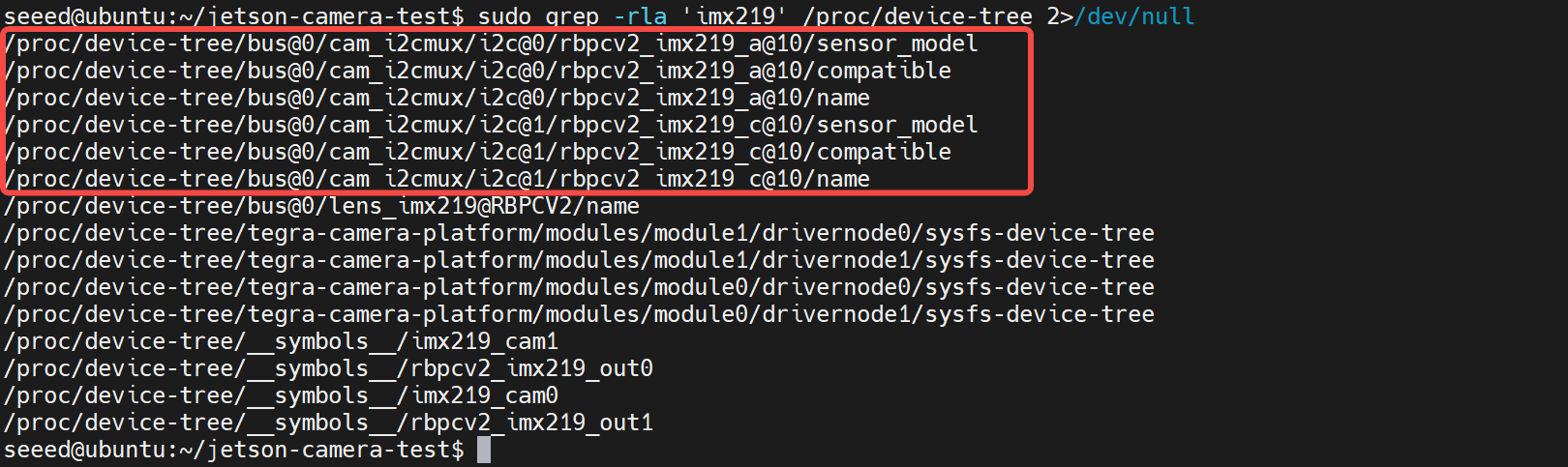
Read the actual Sensor Mode parameters:
CAM=/proc/device-tree/bus@0/cam_i2cmux/i2c@0/rbpcv2_imx219_a@10
ls "$CAM"

for key in \
  num_lanes \
  tegra_sinterface \
  phy_mode \
  mode_type \
  pixel_phase \
  active_w \
  active_h \
  csi_pixel_bit_depth \
  pix_clk_hz
do
  printf "%-25s : " "$key"
  tr -d '\0' < "$CAM/mode0/$key" 2>/dev/null || echo "Not found"
  echo
done
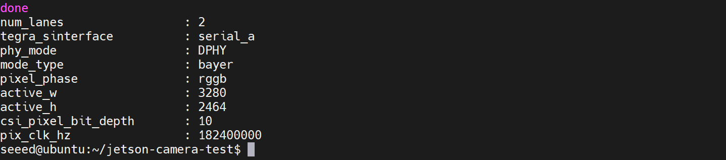
Summary
Through the analysis of the Jetson Camera data chain, we can understand the entire image capture process as the following links: the Sensor is responsible for generating image data, MIPI CSI-2 is responsible for transmission, NVCSI is responsible for receiving, VI is responsible for capture, and the ISP is responsible for image processing.
At the software level, Jetson also provides different ways to access the camera. For driver debugging and raw data analysis, you can capture RAW data through V4L2; for applications that require color processing, auto exposure, and real-time preview, you can obtain processed images through Argus and the ISP.
The real value of understanding this data chain is being able to locate problems more accurately.
Of course, the knowledge involved in the Jetson Camera goes far beyond this. This article focuses on how image data enters the Jetson, but there is still much worth discussing in depth about the format of RAW data itself and the principles of image processing.
References
- https://docs.nvidia.com/jetson/archives/r36.4/DeveloperGuide/SD/CameraDevelopment.html
- https://docs.nvidia.com/jetson/archives/r36.4.4/DeveloperGuide/SD/Multimedia/AcceleratedGstreamer.html
- https://docs.nvidia.com/jetson/archives/r36.4/ApiReference/l4t_mm_10_argus_camera_recording.html
- https://github.com/Seeed-Studio/Linux_for_Tegra
- https://wiki.seeedstudio.com/J401_carrierboard_Hardware_Interfaces_Usage/
- https://wiki.seeedstudio.com/how_to_use_camera_imx219/
Tech Support & Product Discussion
Thank you for choosing our products! We are here to provide you with different support to ensure that your experience with our products is as smooth as possible. We offer several communication channels to cater to different preferences and needs.